Table of Contents
Advertisement
Quick Links
ACS-2170
Intel Celeron N2930 Ultra Slim Fanless Box PC
User Manual
Release Date
Revision
Jul. 2015
V1.0
®2015 Aplex Technology, Inc.
All Rights Reserved.
Published in Taiwan
Aplex Technology, Inc.
15F-1, No.186, Jian Yi Road, Zhonghe District, New Taipei City 235, Taiwan
Tel: 886-2-82262881 Fax: 886-2-82262883 E-mail:
aplex@aplex.com.tw
URL:
www.aplextec.com
Advertisement
Table of Contents

Related Manuals for Aplex ACS-2170


Summary of Contents for Aplex ACS-2170
-
Page 1: User Manual
Intel Celeron N2930 Ultra Slim Fanless Box PC User Manual Release Date Revision Jul. 2015 V1.0 ®2015 Aplex Technology, Inc. All Rights Reserved. Published in Taiwan Aplex Technology, Inc. 15F-1, No.186, Jian Yi Road, Zhonghe District, New Taipei City 235, Taiwan Tel: 886-2-82262881 Fax: 886-2-82262883 E-mail: aplex@aplex.com.tw... -
Page 2: Revision History
Revision History Reversion Date Description 2015/07/14 Official Version ACS-2170 User Manual... -
Page 3: Warning!/Caution/Disclaimer
This information in this document is subject to change without notice. In no event shall Aplex Technology Inc. be liable for damages of any kind, whether incidental or consequential, arising from either the use or misuse of information in this document or in any related materials. -
Page 4: Packing List
Packing List Accessories (as ticked) included in this package are: □ Adaptor □ Driver & manual CD disc □ Other.___________________(please specify) ACS-2170 User Manual... -
Page 5: Safety Precautions
Always disconnect power when the system is not in use. ◆ Disconnect power when you change any hardware devices. For instance, when you connect a jumper or install any cards, a surge of power may damage the electronic components or the whole system. ACS-2170 User Manual... -
Page 6: Table Of Contents
Warning!/Caution/Disclaimer…..........…………………………….…2 Packing List…………………………………….………………………………….…………………………………..3 Safety Precautions……………………………………………………………..……….…..……………………..4 Chapter 1 Getting Started 1.1 Features………………………..………………………...……………………….…..7 1.2 Specifications…………………...……………………………………………….….7 1.3 Dimensions………………………..…………………………………………….….9 1.4 Brief Description of ACS-2170………..….………………………..………10 Chapter 2 Hardware 2.1 Mainboard Introduction…………………..…...…………………………..11 2.2 Specifications…………………………..…….……………………………………11 2.3 Jumpers and Connectors Location….…………………………………...15 2.4 Jumpers Setting and Connectors…..………………………………..……16 Chapter 3 BIOS Setup 3.1 Operations after POST Screen…...…….……...……….…………………45... - Page 7 Figures Figure 1.1: Dimensions of ACS-2170………..………….……………..……………..9 Figure 1.2: Dimensions of ACS-2170 with Din Rail………………………………….9 Figure 1.3: Overview of ACS-2170………………...…….……………………………...10 Figure 1.4: I/O Side of ACS-2170………………………….……………………………...10 Figure 2.1: Mainboard Dimensions…………………….……………………………….14 Figure 2.2: Jumpers and Connectors Location-Board Top…..…………….….15 Figure 2.3: Jumpers and Connectors Location-Board Bottom….………..…15...
-
Page 8: Getting Started
1 x 2-pin connector for power on/off button Storage Space Storage 1 x SD Card slot, up to 32GB 1 x 2.5” SATAII HDD bay (Easy Accessible) Expansion Expansion Slot 1 x mini PCIe slot (full size) Power Power Input 9~36V DC ACS-2170 User Manual... - Page 9 Operating temperature(°C) -40~85℃ Storage temperature(°C) Storage humidity 10 to 90% @ 40°C, non- condensing Certification CE / FCC Class A Operating System Support OS Support Windows Embedded 8.1 Industry Pro Win 7 Pro for Embedded WES7 WE8S ACS-2170 User Manual...
-
Page 10: Dimensions
1.3 Dimensions Standard Figure 1.1: Dimensions of ACS-2170 Din Rail Figure 1.2: Dimensions of ACS-2170 with Din Rail ACS-2170 User Manual... -
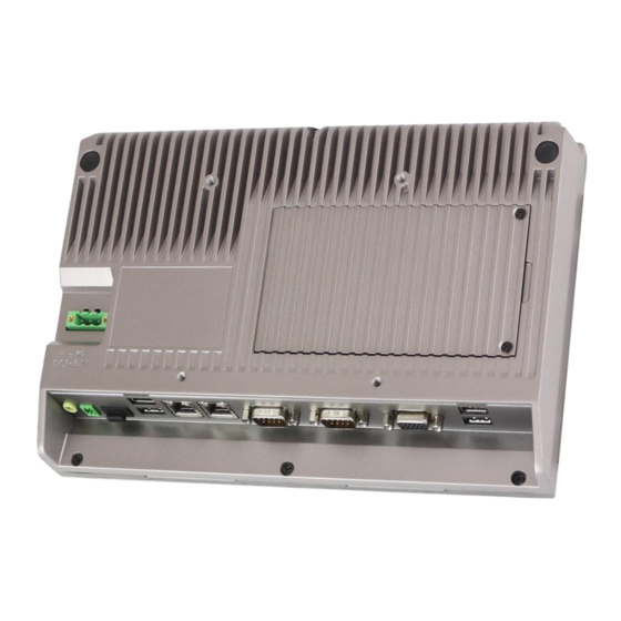
Page 11: Brief Description Of Acs-2170
Data Terminal, TI, Surveillance, etc. and running factory operations from small visual interface and maintenance applications to large control process applications. The ACS-2170 works very well along with any of our display series and it absolutely can provide easy way to perform control and field maintenance. -
Page 12: Chapter 2 Hardware
Up to 1920 x 1200 for HDMI Resolution Up to 1920 x 1200 for LVDS (PS8625) Up to 1920 x 1200 for CRT Dual Display HDMI + LVDS HDMI + CRT LVDS + CRT Super I/O ITE IT8518E ACS-2170 User Manual... - Page 13 Support Line-in, Line-out, MIC by 2x6-pin header Keyboard /Mouse 1 x PS2 keyboard/mouse by box pin header (CN3) Expansion Bus 1 x mini-PCI-express slot 1 x PCI-express (CN3) Touch Ctrl 1 x Touch ctrl header for TCH1 (ITE8518E/COM6) (JP4 setting:RS232 or USB 2.0) ACS-2170 User Manual...
- Page 14 12V /0.70A (Intel Bay Trail N2930 processor with 4GB DDR3L DRAM) 12V /0.60A (Intel Bay Trail E3815 processor with 2GB DDR3L DRAM) EMI/EMS Meet CE/FCC class A 2 x CAN bus TB-528CAN2 1 x SIM Card Socket 1 x mini-PCI-express slot ACS-2170 User Manual...
-
Page 15: Figure 2.1: Mainboard Dimensions
(units :mm) Figure 2.1: Mainboard Dimensions ACS-2170 User Manual... -
Page 16: Jumpers And Connectors Location
2.3 Jumpers and Connectors Location Figure 2.2: Jumpers and Connectors Location- Board Top Figure 2.3: Jumpers and Connectors Location- Board Bottom ACS-2170 User Manual... -
Page 17: Jumpers Setting And Connectors
(Switch),ATX Power and Auto Power on jumper setting. S-422(Switch) Mode Pin6 (Off) ATX Power Pin6 (On) Auto Power on (Default) 5. BAT1 : (1.25mm Pitch 1x2 Wafer Pin Header) 3.0V Li battery is embedded to provide power for CMOS. ACS-2170 User Manual... - Page 18 Power on/off button, They are used to connect power switch button. The two pins are disconnected under normal condition. You may short them temporarily to realize system startup & shutdown or awaken the system from sleep state. ACS-2170 User Manual...
- Page 19 VGA hot plug setting for Windows XP: VGA1 (Pin Header) Function Pin4-Pin6 (Close) VGA Simulation Disabled Pin4-Pin6 (Open) VGA Simulation Enabled Use the 2.0mm jumper cap to close pin4 and pin6 13. HDMI1: (HDMI 19P Connector), High Definition Multimedia Interface connector. ACS-2170 User Manual...
- Page 20 1280*1024 (Default) SBC-7111-E3845-4G 800*480 (option) SBC-7111-N2930-2G 800*600 (option) SBC-7111-E3845-4G 1024*768 (option) SBC-7111-E3815-2G 1920*1080 (option) …… 16. INVT1: (2.0mm Pitch 1x6 wafer Pin Header), Backlight control connector for LVDS. Pin# Signal Name +DC12V +DC12V Ground Ground BKLT_EN_OUT BKLT_CTRL ACS-2170 User Manual...
- Page 21 (2.0mm Pitch 2x2 wafer Pin Header), USB3(CN1) or Touch jumper setting. Function USB3 (CN1) Touch (TCH1) Close 3-4 (default) Open 3-4 (option) Open 1-2 (default) 19. TCH1: (2.0mm Pitch 1x6 wafer Pin Header), internal Touch controller connector. ACS-2170 User Manual...
- Page 22 S_422 Pin# RS232 (Default) OFF: Pin1, Pin2, Pin3, Pin4, Pin5 RS422 (option) ON: Pin1, Pin2, Pin3, Pin4, Pin5 RS485 (option) ON: Pin1, Pin2, Pin3, Pin4, Pin5 S-422 Mode Pin6 (Off) ATX Power Pin6 (On) Auto Power on (Default) ACS-2170 User Manual...
- Page 23 CTS (Clear To Send) JP1 select Setting (RI/5V/12V) BIOS Setup: Advanced/F81216SEC Super IO Configuration/Serial Port 1 Configuration 【RS-232】 RS422 (option) Pin# Signal Name 422_RX+ 422_RX- 422_TX- 422_TX+ Ground BIOS Setup: Advanced/F81216SEC Super IO Configuration/Serial Port 1 Configuration 【RS-422】 ACS-2170 User Manual...
- Page 24 Pin# Signal Name DCD# (Data Carrier Detect) RXD (Received Data) TXD (Transmit Data) DTR (Data Terminal Ready) Ground DSR (Data Set Ready) RTS (Request To Send) CTS (Clear To Send) JP2 select Setting (RI/5V/12V) ACS-2170 User Manual...
- Page 25 (2.0mm Pitch 2X6 Pin Header), Front Audio, An onboard Realtek ALC662-VD codec is used to provide high-quality audio I/O ports. Line Out can be connected to a headphone or amplifier. Line In is used for the connection of external audio ACS-2170 User Manual...
- Page 26 RJ-45 Ethernet ports are provided. Used intel 82574L chipset, LINK LED (green) and ACTIVE LED (yellow) respectively located at the left-hand and right-hand side of the Ethernet port indicate the activity and transmission state of LAN. 37. BUZ1: Onboard buzzer. ACS-2170 User Manual...
- Page 27 Advanced/IT8518Super IO Configuration/Serial Port 1 Configuration【RS-422】 Advanced/IT8518Super IO Configuration/Serial Port 1 Configuration【RS-485】 39. EC_GPIO1: (2.0mm Pitch 1X10 Pin Header),For expand connector, it provides eight GPIO. Pin# Signal Name Ground EC_GPIO1 EC_GPIO2 EC_GPIO3 EC_GPIO4 EC_GPIO5 EC_GPIO6 EC_GPIO7 EC_GPIO8 3.3V ACS-2170 User Manual...
- Page 28 SOC_GPIO23 ICH_GPIO22 GPIO12 GPIO25 SOC_GPIO25 ICH_GPIO24 GPIO24 Ground Ground PCIE_TX0_DN PCIE_TX0_DP PCIE_RX0_DN PCIE_RX0_DP PCIE PCIE Ground Ground PCIE_REFCLK0_DN PCIE_REFCLK0_DP PCIE0_WAKE_N PLTRST_3P3_N SMBUS SMB_CLK_S0 SMB_DATA_S0 SMBUS PCIE PCIE_CLKREQ0_N Ground 3P3V_S5 PWRBTN_ON- Power Auto on 3P3V_S5 3P3V_S5 12V_S0 12V_S0 ACS-2170 User Manual...
- Page 29 USB2.0(USB2), Smbus, SIM and PCIe signal. MPCIe card size is 30x30mm or 30x50.95mm. Signal Name Function support PCIe 1X USB2.0 (USB2) SMBus H1/H2: MPCIE1 SCREW HOLES, H2 for mini PCIE card (30mmx30mm) assemble. H1 for mini PCIE card (30mmx50.95mm) assemble. LED1: Mini PCIe devices LED Status. ACS-2170 User Manual...
- Page 30 (2.0mm Pitch 2x5 Pin Header) ,Front USB connector, it provides one USB port via a dedicated USB cable, speed up to 480Mb/s. Signal Name Pin# Pin# Signal Name 5V_USB23 5V_USB23 USB3_N USB2_N (option, NC) USB3_P USB2_P (option, NC) Ground Ground Ground ACS-2170 User Manual...
- Page 31 TXD (Transmit Data) DTR (Data Terminal Ready) Ground DSR (Data Set Ready) RTS (Request To Send) CTS (Clear To Send) JP5 Setting: Pin1-2: RI (Ring Indicator) (default) Pin3-4 : 5V Standby power (option) Pin5-6: 12V Standby power (option) ACS-2170 User Manual...
- Page 32 Pin3-4 : 5V Standby power (option) Pin5-6: 12V Standby power (option) COM_6(option): (2.0mm Pitch 2X5 Pin Header), COM4 Port, up to one standard RS232 port are provided. They can be used directly via COM cable connection. Signal Name Pin# Pin# Signal Name ACS-2170 User Manual...
- Page 33 Mini PCIe devices LED Status. PS2: (2.0mm Pitch 1X6 Pin Wafer), PS/2 keyboard and mouse port, the port can be connected to PS/2 keyboard or mouse via a dedicated cable for direct used. Pin# Signal Name KBDATA MSDATA Ground KBCLK MSCLK ACS-2170 User Manual...
- Page 34 (2.0mm Pitch 2x3 Pin Header), COM3 setting jumper, pin 1~6 are used to select signal out of pin 9 of COM3 port. JP5 Pin# Function Close 1-2 RI (Ring Indicator) (default) Close 3-4 COM3 Pin9=+5V (option) Close 5-6 COM3 Pin9=+12V (option) ACS-2170 User Manual...
- Page 35 (Type DB9), serial port, standard DB9 serial port is provided to make a direct connection to serial devices. COM4port is controlled by pins No.1~6 of JP6, select output Signal RI or 5V or 12v, for details, please refer to description of JP6. ACS-2170 User Manual...
- Page 36 (2.0mm Pitch 2X5 Pin Header), COM4 Port, up to one standard RS232 port are provided. They can be used directly via COM cable connection. Signal Name Pin# Pin# Signal Name Ground JP6 Setting: RI/5V/12V 43. TB-528C1U2P1/TB-528C1U2(option): SBC-7111 Riser Card, TB-528C1U2P1 CN3 connect to SBC-7111 CN3 pin Header. TB-528C1U2P1 Top: ACS-2170 User Manual...
- Page 37 MPCIE1 SCREW HOLES, H2 for mini PCIE card (30mmx30mm) assemble. H1 for mini PCIE card (30mmx50.95mm) assemble. LED1: Mini PCIe devices LED Status. SIM1(option): (SIM Socket 6 Pin) Support SIM Card devices. PS_ON1: (2.0mm Pitch 1X2 Pin Wafer) ATX Power and Auto Power on jumper setting. ACS-2170 User Manual...
- Page 38 Signal Name Pin# Pin# Signal Name Ground SMB_DATA_R SMB_CLK_R SOC-GPIO22 SOC-GPIO23 SOC-GPIO25 SOC-GPIO24 USB23: (Double stack USB type A), Rear USB connector, it provides up to 2 USB2.0 ports, speed up to 480Mb/s. ACS-2170 User Manual...
- Page 39 COM3 port is controlled by pins No.1~6 of JP5, select output Signal RI or 5V or 12v, for details, please refer to description of JP3. Pin# Signal Name DCD# (Data Carrier Detect) RXD (Received Data) TXD (Transmit Data) DTR (Data Terminal Ready) Ground ACS-2170 User Manual...
- Page 40 PWR BT: POWER on/off Button, They are used to connect power switch button. The two pins are disconnected under normal condition. You may short them temporarily to realize system startup & shutdown or awaken the system from sleep state. PWR LED: POWER LED status. Model TB-528C1U2P1 TB-528C1U2 ACS-2170 User Manual...
- Page 41 Smbus,USB2.0,SIM and PCIe signal. MPCIe card size is 30x30mm or 30x50.95mm Signal Name Function support PCIe 1X USB2.0 (USB2) SMBus H1/H2: MPCIE1 SCREW HOLES, H2 for mini PCIE card (30mmx30mm) assemble. H1 for mini PCIE card (30mmx50.95mm) assemble. LED1: Mini PCIe devices LED Status. ACS-2170 User Manual...
- Page 42 Before connection, make sure that pinout of the USB Cable is in accordance with that of the said tables. Any inconformity may cause system down and even hardware damages. JP_SET(option): (2.0mm Pitch 2x5 Pin Header). Signal Name Pin# Pin# Signal Name 3P3V_S5_USB 3P3V_S5 3P3V_S5_USB 3P3V_S5 ACS-2170 User Manual...
- Page 43 They can be used directly via COM cable connection. Signal Name Pin# Pin# Signal Name Ground GPIO1: (2.0mm Pitch 2x5 Pin Header), General-purpose input/output port, it provides a group of self-programming interfaces to customers for flexible use. ACS-2170 User Manual...
- Page 44 Terminal resistor R+(internally connected to CANH2) CANH2 CAN bus Signal H CANL1 CAN bus Signal L Terminal resistor R-(internally connected to CANL1) CAN1 Shield cable (FG) Terminal resistor R+(internally connected to CANH1) CANH1 CAN bus Signal H 【See TB-528AN2 Manual】 ACS-2170 User Manual...
- Page 45 SBC-7111 Riser Card,TB-528U2 CN3 connect to SBC-7111 CN3 pin Header. TB-528U2 Top: CN3: (1.27mm Pitch 2X30 Pin Header), connect to SBC-7111 CN3 pin Header. USB23: (Double stack USB type A), Rear USB connector, it provides up to 2 USB2.0 ports, speed up to 480Mb/s. ACS-2170 User Manual...
-
Page 46: Bios Setup
BIOS, CPU, memory, and storage devices. 3.2 BIOS Setup Utility Press [Delete] key to enter BIOS Setup utility during POST, and then a main menu containing system summary information will appear. ACS-2170 User Manual... -
Page 47: Main Settings
3.3 Main Settings System Time: Set the system time, the time format is: Hour : 0 to 23 Minute : 0 to 59 ACS-2170 User Manual... -
Page 48: Advanced Settings
Day: Note that the ‘Day’ automatically changes when you set the date. Month: 01 to 12 Date: 01 to 31 Year: 1998 to 2099 3.4 Advanced Settings 3.4.1 ACPI Settings Enable ACPI Auto Conf: [Disabled] [Enabled] Enable Hibernation: ACS-2170 User Manual... - Page 49 Change Settings [Auto] 3.4.3 IT8518 Super IO Configuration Super IO chip IT8518/IT8519 Serial Port 1 Configuration Backlight PWM Controller(COM5): [RS-485] [RS-422] Serial Port 2 Configuration (COM6) Change Settings [Auto] 3.4.4 Intel(R)Smart Connect Technology ISCT Support [Disabled] [Enabled] ACS-2170 User Manual...
- Page 50 Intel HT-X Technology Supported L1 Data Cache 24KB x 4 L1 Code Cache 32KB x 4 L2 Cache 1024KB x 2 L2 Cache Not Present CPU Thermal configuration CPU Speed 1918 MHz 64-bit Supported Hyper-Threading: [Enabled] [Disabled] ACS-2170 User Manual...
- Page 51 3.4.7 PPM Configuration CPU C State Report [Enabled] [Disabled] Max CPU C-state [C7] [C6] [C1] SOix [Disabled] [Enabled] 3.4.8 Thermal Configuration Parameters 3.4.9 IDE Configuration Serial-ATA(SATA) [Enabled] [Disabled] SATA Test Mode [Disabled] [Enabled] SATA Speed Support [Gen2] [Gen1] ACS-2170 User Manual...
- Page 52 SATA Mode [AHCI Mode] [IDE Mode] Serial-ATA Port 0 [Enabled] [Disabled] SATA Port0 Hotplug [Disabled] [Enabled] Serial-ATA Port 1 [Enabled] [Disabled] SATA Port1 Hotplug [Disabled] [Enabled] SATA Port0 Not Present SATA Port1 Not Present 3.4.10 Miscellaneous Configuration ACS-2170 User Manual...
- Page 53 [Enabled] MIPI HSI Support [Disabled] LPSS Configuration LPSS DMA #1 Support [Enabled] LPSS DMA #2 Support [Enabled] LPSS I2C #1 Support [Enabled] LPSS I2C #2 Support [Enabled] LPSS I2C #3 Support [Enabled] LPSS I2C #4 Support [Enabled] ACS-2170 User Manual...
- Page 54 GateA20 Active [Upon Request] [Always] Option ROM Messages [Force BIOS] [Keep Current] Boot option filter [UEFI and Legacy] [Legacy only] [UEFI only] Network [UEFI] [Do not launch] [Legacy] Storage [UEFI] [Do not launch] [Legacy] Video [Legacy] [UEFI] ACS-2170 User Manual...
- Page 55 USB Mass Storage Driver Support [Enabled] [Disabled] USB hardware delays and time-outs: USB transfer time-out: [20 sec] [10 sec] [5 sec] [1 sec] Device reset time-out: [20 sec] [10 sec] [30 sec] [40 sec] Device power-up delay [Auto] [Manual] ACS-2170 User Manual...
-
Page 56: Chipset Settings
Force Lid Status [On] [Off] [Auto] ALS Support [Disabled] IGD Flat Panel [Auto] Pannel Scaling [Auto] ►Memory Frequency and Timing ►Graphics Power Management Control Memory Information Total Memory 4096 MB(DDR3L) Memory Slot0 4096 MB(DDR3L) DIMM#1 Not Present ACS-2170 User Manual... - Page 57 XHCI Mode [Smart Auto] USB2 Link Power Management [Enabled] USB 2.0(EHCI) Support [Enabled] USB EHCI debug [Disabled] USB Per Port Control [Enabled] USB Port 0 [Enabled] USB Port 1 [Enabled] USB Port 2 [Enabled] USB Port 3 [Enabled] ACS-2170 User Manual...
-
Page 58: Security Settings
You may press key to abandon password entry operation. To clear the password, just press Enter key when password input window pops up. A confirmation message will be shown on the screen as to whether the password ACS-2170 User Manual... -
Page 59: Boot Settings
BIOS setup; if Security Option is set to Setup, you will be requested for password for entering BIOS setup. 3.7 Boot Settings Setup Prompt Timeout Bootup Numlock State [On] [off] Quiet Boot [Disabled] ACS-2170 User Manual... -
Page 60: Save & Exit Settings
Sets the system boot order Hard Drive BBS Priorities [SATA PM:*** … ] Boot Option #1 SATA PM:***… ****** Disabled 3.8 Save & Exit Settings Save Changes and Exit Save & Exit Setup save Configuration and exit ? [Yes] [No] ACS-2170 User Manual... - Page 61 Restore User Defaults Restore User Defaults? [Yes] [No] Launch EFI Shell from filesystem device WARNING Not Found [ok] Reset System with ME disable ModeMEUD000 ME will runs into the temporary disable mode, Ignore if ME Ignition FWMEUD001. ACS-2170 User Manual...
-
Page 62: Chapter 4 Installation Of Drivers
Intel chipset driver, VGA driver, LAN drivers, Audio driver, USB 3.0 Driver Installation instructions are given below. Important Note: After installing your Windows operating system, you must install first the Intel Chipset Software Installation Utility before proceeding with the installation of drivers. ACS-2170 User Manual... -
Page 63: Intel(R) Atomtm Soc Chipset
4.1 Intel(R) AtomTM SoC Chipset To install the Intel chipset driver, please follow the steps below. Step 1. Select Intel (R) AtomTM SoC Chipset from the list Step 2. Click Next to setup program. ACS-2170 User Manual... - Page 64 Step 3. Read the license agreement. Click Yes to accept all of the terms of the license agreement. Step 4. Click Next to continue. ACS-2170 User Manual...
- Page 65 Step 5. Click Next. Step 6. Select Yes, I want to restart this computer now. Click Finish, then remove any installation media from the drives. ACS-2170 User Manual...
-
Page 66: Intel(R) Vga Chipset
4.2 Intel(R) VGA Chipset To install the VGA drivers, follow the steps below to proceed with the installation. Step 1.Select Intel(R) VGA Chipset Step 2. Click Automatically run WinSAT and enable the Windows Aero desktop theme(if supported). Click Next. ACS-2170 User Manual... - Page 67 Step 3. Read license agreement. Click Yes. Step 4. Click Next. ACS-2170 User Manual...
- Page 68 Step 5. Click Install. Step 6. Click Install. ACS-2170 User Manual...
- Page 69 Step 7. Click Next. Step 8. Click Yes, I want to restart this computer now. Then click Finish. ACS-2170 User Manual...
-
Page 70: Intel(R) Lan Driver
4.3 Intel(R) LAN Driver To install the Intel (R) LAN driver, please follow the steps below. Step 1. Select Intel(R) 82574L LAN Driver from the list. Step 2. . Click Next. ACS-2170 User Manual... - Page 71 Step 3. Read license agreement. Click I accept the terms in the license agreement. Click Next. Step 4. Click Next to continue. ACS-2170 User Manual...
- Page 72 Step 5. Click Install to begin the installation. Step 6. Click Finish to exit the wizard. ACS-2170 User Manual...
-
Page 73: Realtek Alc662 Hd Audio Driver Installation
4.4 Realtek ALC662 HD Audio Driver Installation To install the Realtek ALC662 HD Audio Driver, please follow the steps below. Step 1. Select Realtek AL662 HD Audio Driver from the list Step 2. Click Next to continue. ACS-2170 User Manual... - Page 74 Step 3. Click Yes, I want to restart my computer now. Click Finish to complete the installation. ACS-2170 User Manual...
-
Page 75: Usb 3.0 Driver
4.5 USB 3.0 Driver To install the USB 3.0 Driver, please follow the steps below. Step 1. Select USB 3.0 Driver from the list Step 2. Click Next to continue. ACS-2170 User Manual... - Page 76 Step 3. Read the license agreement. Then click Yes to continue. Step 4. Click Next to continue. ACS-2170 User Manual...
- Page 77 Step 5. Click Next to continue. Step 6. Select Yes, I want to restart this computer now. Then click Finish to complete the installation. ACS-2170 User Manual...
Need help?
Do you have a question about the ACS-2170 and is the answer not in the manual?
Questions and answers