
Related Manuals for Midtronics PowerSensor Micro700


Summary of Contents for Midtronics PowerSensor Micro700
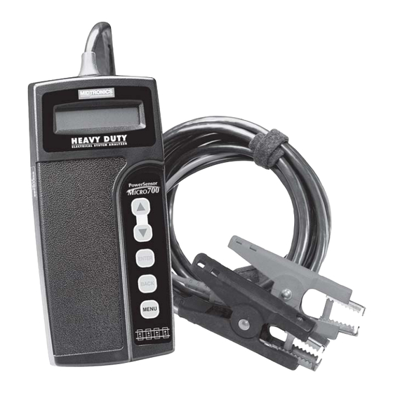
- Page 1 For testing 6- and 12-volt heavy- duty automotive, commercial, and marine batteries and 12- and 24-volt charging systems. INSTRUCTION MANUAL...
-
Page 2: Table Of Contents
TABLE OF CONTENTS TEST PREPARATION ................ 1 CONNECTING THE ANALYZER ..........1 Testing Individual Batteries ..........1 Testing the Battery Pack ............. 2 USING THE KEYPAD ................ 3 OUT-OF-VEHICLE TEST ..............3 BATTERY TEST RESULTS ............5 Testing the Next Battery ............5 Battery Code (for Micro700BMP only) ....... - Page 3 GLOW PLUG DETECTION ............13 SYSTEM SAVER ..............13 OPTIONS MENU ................14 PRINT RESULTS ..............14 PRINTER SELECT ..............14 VIEW RESULTS ............... 14 VOLTMETER ................15 SET ADDRESS ................ 15 PERFORM TEST ..............15 TROUBLESHOOTING ..............16 DISPLAY PROBLEMS ............. 16 PRINTING PROBLEMS ............
-
Page 4: Test Preparation
CAUTION: Because of the possibility of personal injury, always use extreme caution when working with batteries. Follow all BCI (Battery Council International) safety recommendations. WARNING: Battery posts, terminals, and related accesso- ries contain lead and lead compounds, chemicals known to the state of California to cause cancer and birth defects or other reproductive harm. -
Page 5: Testing The Battery Pack
SIDE VIEW VIEW Figure 1. Clamp connection to stud adapter Figure 2. Clamp connection to stud pad Testing the Battery Pack 1. Connect the red clamp to the positive (+) lug on the battery at one end of the pack (Figure 3). 2. -
Page 6: Using The Keypad
USING THE KEYPAD USING THE KEYPAD Press the ARROW buttons to scroll to menu choices. Press and hold to rapidly scroll through lists of battery rating values. Press the ENTER button to make selections. Press the BACK button to move back a step. Press and hold the MENU button to make these options available: •... - Page 7 2. Select the BATTERY CHEMISTRY: LEAD ACID AGM-SPIRAL AGM-OTHER 3. CHOOSE TEST: OUT-OF-VEHICLE Out-of-Vehicle tests individual batteries that are electrically disconnected from the vehicle. Although you can test more than one battery in succession, the analyzer stores for printing or viewing only the results and battery test code from the last battery that you test.
-
Page 8: Battery Test Results
BATTERY TEST RESULTS The Micro700 will display the open circuit voltage, cranking amps based on the units are based on rating system you selected, and one of five battery decisions. The analyzer also generates a battery code that you can view separately. Refer to “Viewing the Battery Test Code.”... -
Page 9: Battery Code (For Micro700Bmp Only)
NOTE: if you want to test up to 6 batteries in succession and store each test result and code for printing and viewing, use the In-Vehicle Battery Pack Test. When you start a new test by connecting to a battery after completing the Battery Pack Test, the analyzer will delete the last test result. -
Page 10: Battery Pack Test
FULL SYSTEM Tests the battery pack, provides the option to test batteries individually, tests the starting system and the charging system. STARTING SYSTEM Tests the starting system only. CHARGING SYSTEM Tests the charging system only. BATTERY PACK TEST You can perform the Battery Pack Test by itself or within a Full System Test The Micro700 can measure battery packs up to 3500 CCA. -
Page 11: Battery Pack Test Results
2. Select the BATTERY TYPE: 12 VOLTS 6 VOLTS 3. Select the battery rating system and rating value as required in the Out-of-Vehicle Battery Test. If necessary, the analyzer will ask if the battery temperature is above or below 32 ºF or whether you are testing before or after charging. -
Page 12: Starting System Test
STARTING SYSTEM TEST You can perform the Starting System Test by itself or within a Full System Test IMPORTANT: Make sure the battery or battery pack is in a good state of charge before the Starting System Test. If the result for the Battery Pack Test was CHECK BAT. -
Page 13: Charge Code (For Micro700Bmp Only)
Charge Code—Starting System (for Micro700BMP only) The display will alternate between screens showing the test results and a 9-character charge code. CHARGING SYSTEM TEST You can perform the Starting System Test by itself or within a Full System Test. When the engine is running, the Micro700 will help you perform the procedure for a charging system analysis. -
Page 14: Charging System Test Results
6. Testing with accessory loads. After the Diode Ripple Test, the Micro700 will ask you to: Turn on accessory loads (headlights, blower motor, defogger, etc.) of at least 40 amps. Test at idle with loads on. Rev engine for another 5 seconds with loads on. IMPORTANT: When asked to turn on the accessory loads, turn on the blower to high (heat), turn on the high-beam headlights and rear defogger. -
Page 15: Load Voltage Measurements
Load Voltage Measurements LOAD OFF Displays the measured voltage taken at idle with accessories off. LOAD ON Displays the measured voltage taken at idle with accessories on. Alternator Ripple Evaluation DIODE RIPPLE NORMAL The alternator’s rectifier is functioning within its normal operating range. -
Page 16: Before And After Charge Tests
BEFORE AND AFTER CHARGE TESTS If necessary, the analyzer will ask you if the battery has just been charged. At the CHOOSE TEST prompt, select AFTER CHARGE or BEFORE CHARGE and press ENTER. GLOW PLUG DETECTION If necessary during the Charging System Test, the analyzer will ask you if the vehicle has glow plugs. -
Page 17: Options Menu
Midtronics printer’s IR receiver below the MODE button. IMPORTANT: If you are using the Midtronics printer for the first time, charge the printer battery for 16 hours before beginning your test session. Refer to the printer manual for more information. -
Page 18: Voltmeter
VOLTMETER The Micro700 can also function as a voltmeter. The operating range of the voltmeter is 0 to 30 volts. IMPORTANT: If the Micro700 is connected to a voltage source greater than 30 volts, the circuit board might be damaged. To use the voltmeter function, press and hold the MENU button. -
Page 19: Troubleshooting
TROUBLESHOOTING DISPLAY PROBLEMS If the display does not turn on: • Check the connection to the vehicle battery or pack. • The vehicle battery may be too low to power the analyzer (below 1 volt). Fully charge the battery and retest. •... -
Page 20: Printing Problems
To turn the printer on, briefly press the MODE button. The green STATUS light should turn on. Make sure you are using the Midtronics printer provided with the Micro700. Other printers may not be compatible. -
Page 21: Replacing The Micro700 Battery
If you are unable to print after ensuring the analyzer is functioning, the printer is on, the battery is good, and the IR transmitter and receiver are aligned, check the printer manual for further instructions or call Midtronics at 800-776-1995 for assistance. REPLACING THE MICRO700 BATTERY... -
Page 22: Patents, Limited Warranty, Service
PATENTS Made in the U.S.A. by Midtronics, Inc. and is protected by one or more of the following U.S. Patents: 6,469,511; 6,456,045; 6,445,158; 6,441,585; 6,392,414; 6,323,650; 6,316,914; 6,310,481; 6,304,087; 6,249,124; 6,225,808; 6,163,156; 6,091,245; 6,051,976; 5,831,435; 5,821,756; 5,757,192; 5,592,093; 5,585,728; 5,572,136;... - Page 23 PN 168-700G 2/04 ©2004 Midtronics, Inc.
Need help?
Do you have a question about the PowerSensor Micro700 and is the answer not in the manual?
Questions and answers