Table of Contents
Advertisement
Quick Links
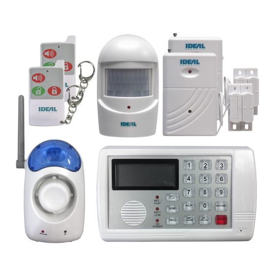
WIRELESS ALARM SYSTEM WITH TELEPHONE AUTO DIALER
YOU!
"
"THE SYSTEM
THAT CALLS
Our WIRELESS ALARM SYSTEM WITH TELEPHONE AUTO DIALER is designed to allow you to
create your own security system. When the AUTO DIALER is connected to a telephone land line
and an electrical outlet and set to ARM mode it will alert you when any of the sensors have been
triggered. The auto-dialer will activate the built-in siren or chime (if set) and dial out (if set) to up to
5 pre-programmed telephone numbers with your own pre-recorded message. You can choose to
remotely listen in & broadcast to the protected perimeter. Once you know the situation, you can take
appropriate actions.
There are no monthly fees to pay!
www.idealalert.ca
SK634
Advertisement
Table of Contents

Related Manuals for Ideal Security SK634


Summary of Contents for Ideal Security SK634
- Page 1 5 pre-programmed telephone numbers with your own pre-recorded message. You can choose to remotely listen in & broadcast to the protected perimeter. Once you know the situation, you can take appropriate actions. There are no monthly fees to pay! www.idealalert.ca SK634...
-
Page 2: This Package Includes
Thank you for choosing Ideal Security’s Home Security System with Telephone Auto Dialer. If you have any questions, problems or comments regarding the installation or operation of this system, please do not hesitate to contact IDEAL’s customer service department through our web site at www.idealalert.ca, via email at info@idealalert.ca, or by calling our toll free number at 800-361-2236 x 230. -
Page 3: Description Of Components
TELEPHONE AUTO DIALER LINE TEL. DESCRIPTION OF COMPONENTS 1. Antenna Jack 5. REC./Play LED 9. Microphone 13. Battery Cover 2. Antenna 6. Battery Low LED 10. To Wall Jack (LINE) 14. Reset Button 3. LCD Display 7. Power LED 11. To Telephone (TEL.) 15. Siren speaker 4. Voice Speaker 8. Numeric Keypad 12. DC 9V Jack... -
Page 4: Auto-Dialer Set-Up
LINE TEL. LINE TEL. (LINE) (TEL.) To wall socket To telephone DC 9V Adaptor ( Fig. 3a ) ( Fig. 3b ) • Wall mount option: Choose a suitable location where you have access to a telephone line and electrical outlet, drill holes using template provided and install anchors and screws. Place the auto-dialer over the screws and slide it down to secure it in place. - Page 5 • Press ARM/DISARM button to confirm. • You are now ready to program up to 5 emergency telephone numbers. Press the */UP or #/DOWN buttons to select memory location from 1 to 5. If you select 2 this is where your number will be stored and it will be the 2nd number dialed. • Enter the telephone number you would like to store, as you would normally dial it in your area (maximum of 32 digits, the screen will only display the last 16 digits), followed by ARM/DISARM to confirm. • Repeat steps for the four other numbers you may wish to store. • DO NOT use 911 as on of the stored telephone numbers. • Press PROG button eight (8) times to exit the set-up mode. 5.
-
Page 6: Installation Of Sensors
10. TO PROGRAM CALL-IN RING DETECT CYCLE (how many rings before auto dialer will answer). The auto dialer has been factory preset to answer after the 5th ring. The call-in ring detect cycle is for how many times you want the phone to ring before the auto-dialer picks up. You can arm/disarm and monitor your home via the telephone. • Enter the password followed by the PROG button seven (7) times. -
Page 7: Battery Low Indicator
• The maximum detection range (left to right) is 110 degrees for a maximum distance up to 8m (26'). • Test the area requiring coverage before mounting the sensor permanently. • The LED on the front of the unit will flash continuously when motion is sensed. • Use the swivel wall mount bracket to mark the mounting location, drill holes and install anchors and attach the bracket with the screws provided. Slide the main unit onto the bracket until it clicks into place (Fig 5). Adjust the bracket to obtain the best coverage of the intended protected area (Fig 6). (Fig. 5) 1.5~2m (5’~6’) 110° 5~8m (16~26’) (Fig. 6) BATTERY LOW INDICATOR When the battery is low, the LED on the front of the unit will flash on 3 seconds and off 1 second. Replace the battery immediately to maintain proper detection. If batteries are low they may send a false signal to the auto-dialer. Batteries in all units should be replaced at least once per year. DOOR/WINDOW SENSORS WITH VIBRATION DETECTION Description of Components Trigger/ battery low LED... - Page 8 WIRELESS INDOOR/OUTDOOR SIREN & STROBE LIGHT Description of Components 1. Antenna 2. Arm / Battery low / Trigger indication LED ( red ) 3. Strobe light 4. AC indication LED ( green ) 5. Siren / Light function switch ALKALINE RECHARGE 6. LEARN button 7. Alkaline / Recharge switch BAT.LOW 8. DC Jack 9. Entry delay switch 10. Battery cover DC 6V LEARN Installation • Remove the screws from the battery compartment cover (Fig. 8). • Set the Entry delay (0 / 10 seconds) timer switch. • Set the battery type switch. WARNING: Failure to choose the correct setting will damage this unit.
-
Page 9: System Operation
SYSTEM OPERATION 1. TO ARM THE SYSTEM • Enter password followed by the ARM/DISARM button or press the ARM button on the remote control. • Three short beeps will sound and the ARM icon will show on the auto-dialer screen. • Wait 60 seconds for a short beep. The auto-dialer is now set at ARM and ready to receive signals. • If an OPEN ZONE condition exists (a door or window is open) the auto dialer will beep for 5 seconds and the screen will show “CLOSE PLEASE” and the zone number of the sensor that triggered the alarm will be flashing. If the zone remains open (the door or window is not closed) after 60 seconds the alarm will sound and the auto dialer will start dialing. 2. ALARM OPTIONS • If the auto-dialer (in ARM mode) receives a signal from any sensor, the screen will display TRIGGER with the zone number. - Page 10 ARM SYSTEM – Enter “5 and #” after three short beeps the system is ARMED and will automatically hang up. If you hear 5 rapid beeps after three short beeps, it means one of your sensors isn’t closed or is activated. The system will give you 5 seconds to enter a new code. DISARM SYSTEM – Enter “6 and #” after a beep the auto-dialer will DISARM and hang up. NOTE: Whether you receive an alarm call or you call the auto dialer, if you enter a wrong password or operation code, the call will disconnect and sound 5 beeps on the auto-dialer.
- Page 11 LINK WIRELESS SENSORS TO THE AUTO DIALER All the units included in this package have been factory linked to the auto dialer. You may link additional sensors, remote controls or sirens to your auto-dialer. In certain circumstances you may have to re-link existing parts. Make sure to test the reception range of all sensors before permanently mounting them.
-
Page 12: Troubleshooting Guide
NOTE: Please preserve this manual. It contains valuable information for properly setting up and operating the system. Please check for updated instructions at www.idealalert.ca WARRANTY: 1 year limited warranty (excluding batteries) on components. Ideal Security Inc. www.idealalert.ca e-mail: info@idealalert.ca Tel.: 1 800-361-2236 EXT. 230...
Need help?
Do you have a question about the SK634 and is the answer not in the manual?
Questions and answers