Wolf MGK-130 Technical Manual And Installation Instructions
Gas condensing boilers
Hide thumbs
Also See for MGK-130:
- Operating instructions manual (8 pages) ,
- Instructions manual (16 pages) ,
- Maintenance instructions manual (32 pages)
Table of Contents
Advertisement
Technical guide and
installation instructions
Gas condensing boilers
MGK-130
MGK-170
MGK-210
MGK-250
MGK-300
These installation instructions are to be retained by the user.
We cannot accept any warranty claims if these operating instructions have not been
observed.
Wolf GmbH · Postfach 1380 · D-84048 Mainburg · Tel. +49-8751/74-0 · Fax +49-8751/741600 · Internet: www.wolf-heiztechnik.de
Document no. 3062880_0910
Subject to technical modifications
GB
Advertisement
Table of Contents

Subscribe to Our Youtube Channel
Related Manuals for Wolf MGK-130


Summary of Contents for Wolf MGK-130
-
Page 1: Installation Instructions
These installation instructions are to be retained by the user. We cannot accept any warranty claims if these operating instructions have not been observed. Wolf GmbH · Postfach 1380 · D-84048 Mainburg · Tel. +49-8751/74-0 · Fax +49-8751/741600 · Internet: www.wolf-heiztechnik.de Document no. 3062880_0910 Subject to technical modifications... -
Page 2: Table Of Contents
Installation ....................14-16 Installation, combustion air supply / flue system ..........17 Electrical connection................17-21 Filling the system / filling the siphon .............22 Checking the gas supply pressure ...............23 Commissioning / Setting the BUS address...........24 Displaying / modifying control parameters............25 Limiting the maximum output................26 Changing the gas type / CO settings ............27-29 Testing the combustion parameters..............30 Commissioning report...................31 Technical information, water treatment ............32 System log ....................33 Engineering data ..................34 Function description / System engineering..........35-36 Technical information, connection on the water side ........37 Engineering information, combustion air / flue gas routing......38-44 Wiring diagram MGK-130 ................45 Wiring diagram MGK-170-300 ..............46 Troubleshooting ....................47 Resistance table ...................48 Keyword index ..................49-51 EC declaration of conformity ................52 3062880_0910... -
Page 3: Safety Instructions
Safety instructions The following symbols and references are used in conjunction with these important instructions concerning personal safety, as well as operational reliability. "Safety instructions" are instructions with which you must comply exactly, to prevent risks and injuries to individuals and material losses on the boiler. -
Page 4: Standards And Regulations
Standards and regulations Obtain the permission of your mains gas supplier and flue Requirements gas inspector prior to the installation of Wolf gas fired The installation of the boiler must be in accordance with the boilers [where appropriate]. relevant requirements of Gas Safety (Installation and Use) Regulations 1998, Health and Safety Document No. 635 (The Electricity at Work Regulations 1989), BS 7671 (IEE Wiring Regulations) and the Water Supply (Water Fitting) Regulations Wolf gas fired boilers must only be installed by a recognised 1999, or The Water Bylaws 2000 (Scotland). It should also... -
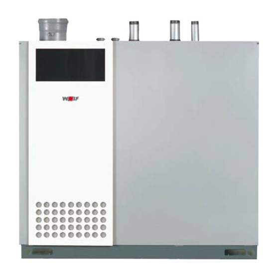
Page 5: Layout Mgk
Otherwise there is a risk of asphyxiation or poisoning. Read these Fig.: Wolf gas condensing boiler installation and maintenance instructions before installing the boiler. Also take the technical engineering information into consideration. -
Page 6: Specification
Specification Type Rated output at 80/60 °C Rated output at 50/30 °C Rated heat input Low boiler output (modul.) at 80/60 °C Low boiler output (modul.) at 50/30 °C Low heat input (modulating) Heat input modulation range 19-100 17-100 17-100 17-100 17-100 Height A mm 1300 1300 1300 1300 1300 Width B mm 1355 1355 1355 1355 Depth C mm Flue diameter Combustion air supply Heating flow outside diameter 1½" 2" 2" 2"... -
Page 7: Control / Function / Operation
Control / Function / Operation ON/OFF switch Reset Thermometer DHW temperature button selector Heating water Illuminated ring temperature selector ON/OFF switch The condensing boiler is OFF in position 0. Reset A fault is reset by pressing the reset button which will also restart the system. Pressing the reset button re-activates the system, if there was no fault. Illuminated status indicator ring Display Explanation Flashing Standby green (power supply ON, no heat demand) Constant Heat demand: Pump running; green light burner OFF Flashing Emissions test mode yellow Constant Burner ON; flame steady yellow light Flashing red Fault DHW temperature selection (only with 3-way valve) - Page 8 Control / Function / Operation Settings Winter mode (position 2 to 8) In winter mode, the boiler heats the heating water to the temperature selected at the heating water controller. According to the pump operating mode, the circulation pump operates constantly (factory setting) or only in parallel with the burner activation / run-on period. Summer mode Winter mode is disabled by rotating the heating water temperature selector into position . In other words, the boiler will then operate in summer mode. Summer mode (heating OFF) means only DHW heating. Frost protection for the heating system and pump anti-seizing protection, however, remain enabled. Emissions test mode The emissions test mode is activated by rotating the heating water temperature selector into position . The indicator ring flashes yellow. After the emissions test mode has been activated, the boiler will heat with the set maximum output. Any previous cycle block will be cancelled. The emissions test mode terminates after 15 minutes or when the maximum flow temperature has been exceeded.
-
Page 9: Delivered Condition / Connections
Delivered condition / Connections Delivered condition The standard delivery includes: 1 Gas condensing boiler, fully wired 1 Technical guide and installation instructions 1 Operating instructions 4 Lifting slings Connections Heating flow Heating return Power cable inlet 230 V Cable inlet 24V Gas connection Grommet Condensate hose C o m b u s t i o n a i r supply * Ø160 Flue outlet with integral test nipple Ø160 / Ø200 Condensate drain... -
Page 10: Installation Instructions / Dimensions
Installation instructions General tips regarding location Dim. B MGK-130 995 mm • The boiler should be installed on a level surface which Dim. B MGK-170/210/250/300 1355 mm is substantial enough to carry its weight. • The boiler must be level (level with adjustable feet). The boiler must only be installed in a room that is protected from frost. Drain the boiler and the entire heating system if there is a risk of frost, when the system has been shut down, to prevent pipes from bursting. Boilers should not be installed in areas subject to aggressive vapours, very dusty or highly Boiler in the installation room humid conditions (workshops, laundry rooms, hobby rooms etc.). This prevents the optimum burner function from being achieved. The combustion air supplied to the boiler must be free from halogenated hydrocarbons (e.g. - Page 11 Transportation into the installation room To ease the transportation into the boiler room, lifting slings are supplied with the boiler. Never use sack trucks. Lifting eyes for lifting slings Fig.: Lifting eyes for lifting slings Levelling the boiler with the adjustable feet At the factory the boiler is equipped with four adjustable feet. • Level the boiler with the adjustable feet, spanner size 13). Fig.: Feet Dimensions MGK-130 MGK-170/210/250/300 Fig.: Dimensions (Total height incl. connector MGK-130 ... 250 = 1460 mm MGK-300 = 1510 mm) Fig.: Connection dimensions 3062880_0910...
-
Page 12: Dismantling, Casing
Dismantling, casing Dismantling the casing Fig.: Dismantling the front and side casing 3062880_0910... -
Page 13: Boiler System Pipework
Boiler system pipework Heating system flow and return are at the top of the boiler. For connections, see Fig. Always provide shut off valves for the flow and the return. Install a check valve downstream of the heating circuit Heating flow Heating return pump(s) to prevent incorrect circulation. For new systems we recommend the installation of a blow-down tank (alternatively a dirt filter) into the return. For older systems this installation is compulsory. Install a safety assembly comprising a safety valve with a response pressure of 6 bar, a pressure gauge and an automatic air vent valve. -
Page 14: Installation
The design information for water treatment must be observed, otherwise system damage due to water leaks may occur. Wolf does not assume liability for any damage to the heat exchanger caused by oxygen diffusion in the heating water. In the event of oxygen penetrating the system, we recommend a system separation through the interconnection of a heat exchanger. - Page 15 Installation Condensate connection Fill the siphon with water prior to commissioning. Otherwise there is a risk of flue gas escaping. When routing condensate into the public sewer system, observe local regulations. If condensate is directly routed to the public sewer, ensure ventilation, so that the public sewer cannot affect the condensing boiler. Use only plastic for all condensate drain pipes. Siphon Fig.: Siphon Neutralising system (accessory) The neutralising system can be connected directly to the appliance. Consumption approx. 10-30 g/kW p.a. Observe the associated instructions. Trim the connection hoses, so that - the condensate can drain fully - backup loops are prevented - a perfect seal is ensured.
- Page 16 Prior to commissioning, test all pipe and gas connections for leaks. Inappropriate installation or using unsuitable components or assemblies may lead to gas escaping, which results in a risk of poisoning and explosion. Install a gas ball valve with fire protection in the gas supply line upstream of the Wolf condensing boiler. Otherwise explosions may occur during a fire. Size the gas supply line in accordance with local regulations. Check the gas line for tightness without the boiler.
-
Page 17: Installation, Combustion Air Supply / Flue System
Installation, combustion air supply / flue system / electrical connection Only use original Wolf components or CE-designated flue systems to create flue lines. Combustion air Flue Observe the technical information regarding ventilation air supply / flue systems prior to installing the flue or the ventilation air connection. -
Page 18: Electrical Connection
Electrical connection Terminal box The control, regulating and safety equipment are fully wired and tested. You only need to connect the power supply and the external accessories. Power supply Programmable Programmable Power supply Outside Create a permanent connection for the power supply. output input, floating 230 V temperature AC/50 Hz 230 V sensor Provide the power supply via a main isolator (heating AC/50Hz Power supply, heating circuit system emergency stop switch) that ensures at least (Controller, radio clock, AF with pump 230 V AC/50 Hz/max. - Page 19 400 VA) Insert the cable glands into the terminal box. Insert and secure the cable through the cable entry. Connect the heating circuit pump 230 V AC to terminals L1, N and Fig.: Connection, heating circuit pump Wiring diagram, ventilation air damper (not for MGK-130) Note: The contractor parameter HG13/GB13 (input 1) must be set to 5 (factory setting for supply air damper) and o o o o o o...
- Page 20 Electrical connection Connection output A1 (230 V AC; 200 VA) Insert the cable glands into the terminal box. Insert and secure the connecting cable through the cable gland. Terminate the connecting cable at terminals L1, N and The parameters for output A1 are described in the table. Fig.: Connection output A1 The functions of output A1 can be scanned and adjusted with eBUS-enabled Wolf control accessories. The following functions can be allocated to output A1: Code Explanation No function Output A1 is not switched DHW circulation pump 100% Output A1 is switched by control accessory (BM) if DHW circulation has been enabled. Output A1 is constantly activated when no accessory controller is installed. DHW circulation pump 50% Output A1 is switched by control accessories (BM) in cycles if DHW circulation has been enabled. 5 minutes ON and...
- Page 21 Input E1 must be closed within 12 seconds after the pump has been switched. Where this is not the case, the burner will be switched OFF, and fault 41 will be displayed. Monitoring, ventilation air damper (factory setting E1) See parameters of output A1, no. 7 ventilation damper. Connection, digital Wolf control accessories Only connect control units from the Wolf accessory range. Each accessory is supplied with its own connection diagram. Use a two-core cable (cross-section > 0.5 mm²) as the connecting cable between the control unit accessory and the condensing boiler.
-
Page 22: Filling The System / Filling The Siphon
Filling the system / filling the siphon Fill the system and vent it correctly in line with the details in the chapter "Water treatment" to ensure the perfect function of the condensing boiler (see page 30). Before connecting the gas condensing boiler, flush the heating system to remove residues such as welding pearls, hemp, putty, etc. from the pipework. Thermometer ON/OFF switch Reset button • The gas tap must be shut. Fig.: Control unit overview • Open the air vent valves. • Open all heating circuits. • Open all radiator or mixer valves. • Slowly fill the entire heating system and boiler when cold, for example via the BDF valve at the return, to approx. 2 bar pressure. Inhibitors are not permissible. • Open the flow valves on the condensing boiler. • Fill the heating system to 2 bar pressure. In operation, the pressure gauge must indicate between 1.5 and 5.5 bar. • Check the entire system for water leaks. -
Page 23: Checking The Gas Supply Pressure
Checking the gas supply pressure Checking the gas supply pressure MGK-130 MGK-170/210/250/300 (Gas flow pressure) Work on gas components must only be performed by a licensed gas fitter. Work which is carried out incorrectly may lead to gas escaping, resulting in a risk of explosion, asphyxiation or poisoning. -
Page 24: Commissioning / Setting The Bus Address
Commissioning Only qualified personnel must carry out the Saving energy commissioning and operation of the boiler, as well as instruct the user. • Instruct the customer about energy saving options. • Check that the power supply has been switched OFF. •... -
Page 25: Displaying / Modifying Control Parameters
Displaying / modifying control parameters Modifications must only be carried out by To prevent damage to the heating system, a recognised heating contractor or by Wolf cancel night setback when outside customer service. temperatures fall below −12 °C. If this rule... -
Page 26: Limiting The Maximum Output
MGK-170 Output (kW) Display value (%) MGK 210 Output (kW) Display value (%) MGK 250 Output (kW) Display value (%) MGK-300 Output (kW) Display value (%) Table: Output setting Limiting the maximum output relative to a flow/return temperature of 80/60 °C Settings for parameter GB04 with eBUS-enabled Wolf connection accessories in [%] 3062880_0910... - Page 27 Otherwise there gas type. is a risk of damage to the appliance. Carefully turn the screw fully home and then undo as follows: Standard setting for different gas types: Turn anti- clockwise Converting the MGK-130 to LPG P A separate conversion kit with gas restrictor, gas combination valve and boiler coding card is required Natural gas H for this conversion. Observe the information in the conversion instructions supplied. Type...
- Page 28 • Turn clockwise - lowers CO content Appliance open (without casing) at lower load • Turn anti-clockwise - raises CO content Natural gas H 9.0% ± 0.2% Appliance open (without casing) at upper load Natural gas H 9.2% ± 0.2% • Terminate the emissions test mode by returning the MGK-130 MGK-170/210/250/300 temperature selector to its original position. Test port, flue gas Zero point adjusting screw, Tx40 Torx (under the Fig.: Flue gas test at the integral test port cover) MGK-130 MGK-170/210/250/300 Fig.: Gas combination valve...
-
Page 29: Changing The Gas Type / Co Settings
Check the standard settings of the zero point and throughput adjusting screws at the GCV and restrictor. • Repeat the adjusting process from section A. • The condensing boiler is correctly adjusted when the values correspond to those in the table below. Appliance closed (without casing) at upper load Natural gas H 9.3% ± 0.3% Appliance closed (with casing) at lower load Natural gas H 9.1% ± 0.3% MGK-130 MGK-170/210/250/300 Zero point adjusting screw, Tx40 Torx (under the cover) Gas throughput adjusting screw (under cover) Allen screw 3 mm for the MGK-170 - MGK-300) Slotted screw for the MGK-130 Fig.: Gas combination valve... -
Page 30: Testing The Combustion Parameters
Testing the combustion parameters Test the combustion parameters with the boiler closed! Testing the combustion air - Hold the test probe into the combustion air supply and calibrate the tester - for balanced flue operation, insert the test probe into the ventilation air adaptor. Start the gas condensing boiler and turn the heating water temperature selector to the emissions test symbol. (The status display ring flashes yellow.) - Check the temperature and enter it in the commissioning report. - After the test has been completed, switch the boiler OFF, remove the test probe and close the test port, if appropriate. Ensure the screws are seated firmly. - Return the temperature selector into its original position. Test port, "Inlet air" flue gas test port ON/OFF switch Temperature selector Testing the flue gas parameters Flue gas can escape into the installation room, if the test port is left open. -
Page 31: Commissioning Report
Commissioning report Commissioning steps Test value or confirmation □ 1.) Gas type Natural gas H □ LPG Wobbe index ___________ kWh/m³ Calorific value, heating ___________ kWh/m³ □ 2.) Gas supply pressure checked? □ 3.) Gas leak test carried out? □ 4.) Balanced flue system checked? □ 5.) Water connections checked for leaks? □ 6.) Siphon filled? □ 7.) Has the system been filled in acc. with the technical information regarding water treatment? □ 8.) Boiler and system vented? □ 9.) System pressure 1.5 - 2.5 bar? □... -
Page 32: Technical Information, Water Treatment
Technical information, water treatment The use of chemical additives and softening using If the total hardness is too high, some of the fill and top- single-stage ion exchangers is not permissible. up water must be desalinated. A % desalinated water should be added: Permissible methods: - Desalination via mixed bed cartridges: These are multi- stage ion exchangers. We recommend, for example, A = 100% – [(C – 0.1 °dH) / (C – 0.1 °dH)] x 100% using GD/GDE cartridges from Grünbeck for the first fill, and later as and when required - Desalination via reverse osmosis Maximum permissible total hardness - Topping up with distilled water max in °dH Total hardness of the untreated Treating the heating water DHW DHW in °dH We recommend a heating water pH value of between 6.5 and 9.0, also in mixed installations comprising various... -
Page 33: System Log
System log Planning Location Boiler output Lowest boiler output Lowest boiler output for the Bmin system System output = Q B,tot B,tot System volume system Maximum expected top- Total volume expected during the top-up up water volume system service life Volume of fill and top-up max system top-up water Total hardness of the °dH e.g. from an analysis of the water supply Checking the specific l/kW = V / Q greater A, specific A, specific system Kminimum system volume / less than 20 l/kW Permissible total °dH Maximum permissible total... -
Page 34: Engineering Data
28 K, the output is reduced. If 38 K is nevertheless reached, the burner shuts down briefly without a fault message. This characteristic must be taken into account when selecting the components (e.g. pumps, heat exchanger and cylinder). Max. flow rate Excessive flow velocities may lead to erosion. Maximum flow rate at Q MGK-130 9.4 m³/h max MGK-170 13.6 m³/h MGK-210 16.4 m³/h MGK-250 19.1 m³/h... -
Page 35: Function Description / System Engineering
Function description / System engineering Control units Control units for appliances with a low loss header with KM/MM Programming module Generally, at least one programming module BM is required. This enables both individual heating circuits and up to 8 heating circuits (1 direct and 7 mixer circuits) to be operated and adjusted. DHW cylinder Cylinder heating is controlled by the KM or MM. The cylinder sensor is connected to E1 of the KM/MM and the cylinder primary pump to A1 of the KM/MM, see installation instructions for KM/MM. Heating circuit / The cascade module KM comprises a cascade control for switching and modulating boilers, including a header sensor that acts as a common flow mixer circuit KM sensor. The KM also comprises a mixer circuit control and the control for a... - Page 36 Function description / System engineering Convector heater With a mixer module or cascade module in configuration 2 or 11, a floating switching input can be used for heat demand for convector heaters. The DigiPro, which communicates with the MM via eBUS, can also be used. Up to 32 subscribers in up to 8 zones can be controlled. Solar The SM1 solar module controls a single circuit system (1 collector array and SM1 solar module 1 cylinder). The SM1 solar module must be connected to the eBUS for operation via a central BM. Only one solar module should be connected to the eBUS. Without the eBUS, a BM-Solar can be used. SM2 solar module The SM2 solar module can control up to two solar circuits (2 collector arrays and 2 cylinders). The SM2 solar module must be connected to the eBUS for operation via a central BM. Only one solar module should be connected to the eBUS. Without the eBUS, a BM-Solar can be used.
-
Page 37: Technical Information, Connection On The Water Side
Technical information, connection on the water side Regarding the fill and top-up water, take the water treatment technical information into account. In larger systems, the circulation pumps should be sized individually to the circuits, and the pump assemblies should therefore be selected in line with demand. -
Page 38: Engineering Information, Combustion Air / Flue Gas Routing
Engineering information, combustion air / flue gas routing Ventilation air/flue gas routing Connection types Operating mode Can be connected to Boiler Gas boiler Category type type 1) Germany Open flue Balanced Moisture- Room Room Building Moisture- flue resistant sealed sealed Regulation resistant flue chimney balanced balanced approved flue... - Page 39 MGK-170, -210, -250, -300 Q = 150 Pa / 10 Pa Flue DN 160 made from PP with approval number CE 0036CPD9169003 Flue DN 200 made from PP with approval number CE 0036CPD9169003 Use exclusively original Wolf components 3062880_0910...
- Page 40 Engineering information, combustion air / flue gas routing Examples for MGK system layout Example: open flue B 23 Install all horizontal ventilation air lines/flues with approx. 3% slope 1 Gas condensing boiler with integral flue gas test (5 cm/m) towards the appliance. Any condensate must flow back to nipple the appliance. 2 Inspection bend 87° DN 160 3 Flue pipe DN 160 Length: 500/1000/2000 4 Wall bezel 5 87° support bend DN 160 with support rail 6 Spacer 7 Ventilation air adaptor (for balanced flue operation) Maintain the following clearance between the internal duct wall and the flue: - 30 mm for circular ducts - 20 mm for square ducts Example: balanced flue C 53 Install all horizontal ventilation air lines/flues with approx. 3% slope...
- Page 41 Engineering information, combustion air / flue gas routing Examples for MGK system layout Example: balanced flue C 33 Install all horizontal ventilation air lines/flues 1 Gas condensing boiler with integral flue gas test with approx. 3% slope (5 cm/m) towards the nipple boiler. Any condensate must flow back to the 2 Inspection bends 87° DN 160 appliance. 3 Flue pipes DN 160 Length: 500/1000/2000 4 Wall bezel 5 87° support bend DN 160 with support rail 6 Spacer 7 Ventilation air adaptor (for balanced flue operation) Maintain the following clearance between the internal duct wall and the flue: - 30 mm for circular ducts - 20 mm for square ducts Maximum length acc.
- Page 42 Engineering information, combustion air / flue gas routing MGK scheme with vertical roof outlet, balanced flue Flue gas from the MGK Vertical roof outlet Ø 160/225 Mat.no. 2651346 + Mat.no. 2651347 + Mat.no. 2651350 Ventilation air to the MGK Flat roof collar Ø 225 Mat.no. 2651458 Adaptor for balanced flue operation Mat.no. 2651332 3062880_0910...
- Page 43 Engineering information, combustion air / flue gas routing MGK concentric C33 scheme MGK façade C53 scheme 3062880_0910...
- Page 44 50 cm from the flue outlet or with EN 13384-1, maintain a maximum back upstream/downstream of diverters to prevent pressure of up to 130Pa in to header line; this the pipe joints being pulled apart. If this is not should also not be exceeded. done, there is a danger of poisoning caused by escaping flue gas. Furthermore, boiler damage As protection against contamination during the building may result. phase, we recommend the use of the complete ventilation air filter for MGK-130 to 300 (part no. 9751390). The ventilation air filter is plugged into the air intake. To prevent flue gas escaping, a positive pressure flue cascade is only permitted with Keep the door of the condensing boiler shut a tested flue gas damper (part no. 2482896). during the building phase. After completing the For the MGK-130, this is already integrated. building phase, remove the filter. 3062880_0910...
-
Page 45: Wiring Diagram Mgk-130
Wiring diagram MGK-130 3062880_0910... -
Page 46: Wiring Diagram Mgk-170-300
Wiring diagram MGK-170-300 3062880_0910... -
Page 47: Troubleshooting
Troubleshooting Any faults will be displayed as fault codes by Wolf controllers with eBUS capability. Cause and remedy may be allocated to these faults using the following table. This table is designed to allow your local heating contractor to trace the fault more easily. Fault Fault Cause Remedy code TBV excess The flow temperature has exceeded the limit Check the system pressure. Check the heating temperature, for the TBV shutdown temperature, or the circuit pump. Vent the system. Press the reset water pressure too low condensate lifting pump (accessory) has button developed a fault or the water pressure switch Check the condensate pump switches off at a pressure < 1.0 bar Increase system pressure... -
Page 48: Resistance Table
Resistance table Boiler sensor, cylinder sensor, solar cylinder sensor, outside temperature Sensor resistances sensor, return sensor, flow sensor, header sensor Temp. °C Resist. Ω Temp. °C Resist. Ω Temp. °C Resist. Ω Temp. °C Resist. Ω 51393 8233 1870 48487 7857 1800 45762 7501 1733 43207 7162 1669 40810 6841 1608 38560 6536 1549 36447 6247 1493 34463 5972 1438 32599 5710 1387 30846 5461... -
Page 49: Keyword Index
Condensate drain, single boiler systems ..........15 Condensate lifting system (accessory) ..........16 Connection of a Wolf cylinder ............. 16 Contents ....................2 Control unit ................... 7 Conversion kits, MGK LPG..............27 Converting MGK-170/210/250/300 to natural gas LL / P ....27 Converting the MGK-130 to LPG P ............ 27 Delivered condition ................9 DHW temperature selector ..............7 Digital Wolf control accessories, connection ........21 Dimensions ..................11 Dismantling the casing ............... 12 Drain valve.................... 5 Electrical connection, general information .......... - Page 50 Keyword index Installation instructions ............... 10 Intake air ..................... 30 Ionisation electrode ................5 Layout MGK..................5 Levelling the boiler with the adjustable feet ........11 Minimum wall clearances ..............10 Neutralising system (accessory)............15 ON/OFF switch ..................7 Output A1, connection ................ 20 Output A1, possible functions ............. 20 Output setting ..................26 Outside temperature sensor connection..........21 Overview, connections MGK ..............9 Power supply ..................18 Pressure drop, heating water .............
- Page 51 Keyword index Ventilation air damper, wiring diagram..........19 Ventilation air/flue gas routing, maximum length ........ 39 Ventilation air/flue gas routing, overview ..........38 Ventilation air/flue gas routing, type of connections ......38 Volume flow max................34 Water pressure switch ................5 Water treatment .................. 32 Winter mode ..................8 3062880_0910...
-
Page 52: Ec Declaration Of Conformity
3062880 Issued by: Wolf GmbH Address: Industriestr. 1 D-84048 Mainburg Product: Gas condensing boiler The product described above conforms to the requirements specified in the following documents: DIN EN 437, 09/2009 DIN EN 483, 06/2000 DIN EN 677, 08/1998 In accordance with the following Directives: 2009/142/EEC (Gas Appliances Directive) 92/42/EEC (Efficiency Directive) 2004/108/EC (EMC Directive) 2006/95/EC (Low Voltage Directive) This product is identified as follows: Mainburg, 16.11.2009 Gerdewan Jacobs Klaus Grabmaier Technical Management Product approval Wolf GmbH · Postfach 1380 · D-84048 Mainburg · Tel. +49-8751/74-0 · Fax +49-8751/741600 · Internet: www.wolf-heiztechnik.de...
Need help?
Do you have a question about the MGK-130 and is the answer not in the manual?
Questions and answers