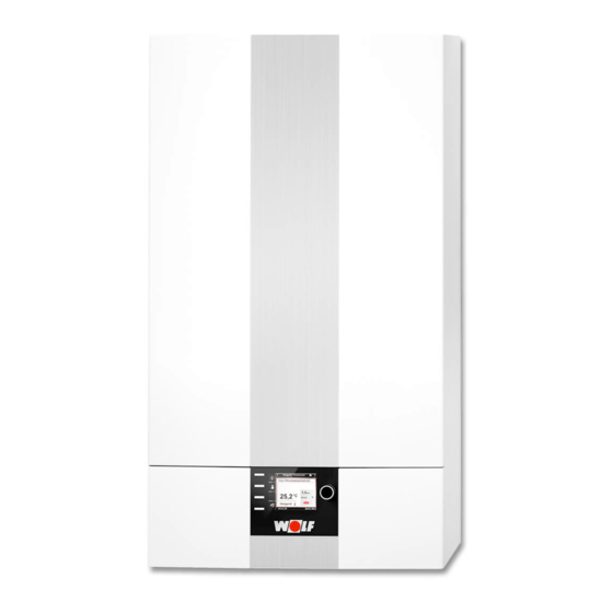
Wolf CGB-2 Service Instructions Manual
Gas condensing boilers
Hide thumbs
Also See for CGB-2:
- Installation instructions for contractors (108 pages) ,
- Instructions manual (28 pages) ,
- Installation and operating instructions manual (34 pages)
Table of Contents
Advertisement
Advertisement
Table of Contents

Subscribe to Our Youtube Channel
Related Manuals for Wolf CGB-2


Summary of Contents for Wolf CGB-2
- Page 1 Service instructions for contractors Gas condensing boilers CGB-2 (K) CGW-2 CGS-2 L/R from 2016 on WOLF GMBH / POSTFACH 1380 / D-84048 MAINBURG / TEL. +49.0.875174-0 / FAX +49.0.875174-1600 / www.WOLF.eu Art.-Nr.: 3064812_201804 Subject to technical modifications...
-
Page 2: Table Of Contents
Table of contents Safety instructions ................... 3 Checking fault messages ................ 6 CGB-2 appliance description ..............7 CGB-2K appliance description ..............8 CGW-2 appliance description ..............9 CGS-2L appliance description ............... 10 CGS-2R appliance description .............. 11 Maintenance equipment Maintenance spare parts set ..............12 Preparing for inspection/ maintenance .................. -
Page 3: Safety Instructions
Only operate the gas condensing boiler within its output a risk to health or death. The main terminals are range, which is stated in the technical documentation ‘live’, even when the ON/OFF switch is in the OFF supplied by WOLF. Intended use of the boiler includes position. exclusive use for hot water heating systems in accord- ance with EN 12828. - Page 4 - (DVGW - TRGI 2008 - G600). We recommend arranging a suitable maintenance contract. - The operator is responsible for the safety, environmental compatibility and energy quality of the heating system (German Immission Control Act/Energy Saving Ordinance) [Germany]. - Only use genuine WOLF spare parts. 3064812_201804...
- Page 5 1. Safety instructions Fig: Terminal box: Danger from 'live' electrical compo- Fig: Gas connection: Risk of poisoning or explosion in nents the event of gas escaping Gaskombiventil Fig: Ignition transformer, high voltage ignition electrode, Fig: Gas combination valve combustion chamber Danger from 'live' electrical components Danger from 'live' electrical components, risk of burning Escaping gas may cause poisoning or an explosion from hot components...
-
Page 6: Checking Fault Messages
Either an AM display module or a BM-2 programming unit can be installed in the front panel for operating the appliance. The ON/OFF switch (integrated in the Wolf logo) switches the appliance off across all poles. Front panel with integral... -
Page 7: Cgb-2 Appliance Description
3. CGB-2 appliance description CGB-2 Wall mounted gas condensing boiler 1 Gas fan 11 Burner 2 Expansion vessel 12 Heating water heat exchanger 3 Mixing valve 13 Flue gas temperature sensor 4 Gas valve 14 Pressure sensor 5 Trap 15 Return temperature sensor... -
Page 8: Cgb-2K Appliance Description
4. CGB-2K appliance description CGB-2K Wall mounted gas condensing combi boiler 1 Gas fan 13 Flue gas temperature sensor 2 Expansion vessel 14 Pressure sensor 3 Mixing valve 15 Return temperature sensor 4 Gas valve 16 Boiler water temperature sensor 5 Trap 17 Heating circuit pump with air vent valve 6 3-way valve 18 Plate heat exchanger... -
Page 9: Cgw-2 Appliance Description
5. CGW-2 appliance description CGW-2 Gas condensing centre 1 Flue pipe 14 Heating flow (accessory) 2 Combustion chamber cover HLSC (thermostat) 15 Gas supply pipe 3 Combustion chamber temperature sensor 16 Heating return (accessory) (eHLSC sensor) 17 Burner 4 Gas fan 18 Heating water heat exchanger 5 Expansion vessel 19 Flue gas temperature sensor 6 Mixing valve... -
Page 10: Cgs-2L Appliance Description
6. CGS-2L appliance description CGS-2L Gas condensing centre 1 Gas fan 16 Combustion chamber temperature sensor (eHLSC sensor) 2 Expansion vessel 17 Burner 3 Mixing valve 18 Heating water heat exchanger 4 Gas valve 19 Flue gas temperature sensor 5 3-way valve 20 Pressure sensor 6 Trap 21 Return temperature sensor 7 Control unit enclosure... -
Page 11: Cgs-2R Appliance Description
7. CGS-2R appliance description CGS-2R Gas condensing centre 1 Gas fan 15 Combustion chamber temperature sensor (eHLSC sensor) 2 Expansion vessel 16 Burner 3 Mixing valve 17 Heating water heat exchanger 4 Gas valve 18 Flue gas temperature sensor 5 3-way valve 19 Pressure sensor 6 Trap 20 Return temperature sensor 7 Control unit enclosure... -
Page 12: Maintenance Equipment Maintenance Spare Parts Set
8. Maintenance equipment Maintenance spare parts set Maintenance requires the following: Maintenance set Part no. 86 14 984 Cleaning set Part no. 86 03 194 Measuring instrument for immission test [BImSch - Germany] We recommend you carry the following parts in your service kit: Universal installation key Part no. 17 31 146 Flue gas temperature sensor Part no. 27 45 24 399 Displacer Part no. -
Page 13: Preparing For Inspection/ Maintenance
9. Preparing for inspection/ maintenance Isolating the system from the power supply The mains terminals remain 'live' even when the ON/OFF switch has been switched OFF. - Disconnect the system from the power supply. Close the gas ball valve. Opening the CGW-2 First, grip the control unit cover on the r.h. side and swivel to the side. Then undo the two screws on the r.h. -
Page 14: Opening The Combustion Chamber
Various components may be very hot. Let them cool down or wear gloves. Release the lock of the gas supply pipe to the mixing chamber. Press the locking lever and push the gas pipe upwards. (O-ring will be visible.) Disconnect both connection plugs on the gas fan. Pull out the monitoring electrode and HLSC plugs. Pull out the ignition transformer plug. Fit the Wolf cleaning vessel to the appliance. Pull out the locking clip from the bottom rotary entry at the bottom. 3064812_201804... -
Page 15: Checking The Burner
11. Checking the burner Position the installation key (accessory) and lift the combustion chamber and swing it out. The heating water does not need to be drained as the work can be carried out at system pressure. ● Visual inspection of gaskets of gas supply Inspet and if required replace gaskets of gas supply to mixing chamber. - Page 16 11. Checking the burner Removing the combustion chamber cover Open the retaining tabs for the combustion chamber cover at the front and back. Lift off the gas fan unit with the combustion chamber cover. ● Visual burner inspection In principle, the burner is maintenance-free. Carry out a visual check of the burner for damage or deposits.
-
Page 17: Checking The Ionisation And Ignition Electrodes
12. Checking the ionisation and ignition electrodes Repacing the ignition electrode Replace ignition electrode with every maintenance. Check spacings and adapt if not correct. Replacing the ionisation electrode Replace ionisation electrode with every maintenance. Tighten the electrode fixing screws with a torque of 3,0 Nm.! Carry out a 100 % calibration after working on the ionisation electrode. -
Page 18: Cleaning The Heat Exchanger
13. Cleaning the heat exchanger The heat exchanger can be cleaned under pressure and with swung out combustion chamber. Push the combustion chamber module upwards (loosen if necessary). Then rotate and remove it downwards. Cleaning the cobustion chamber Never use a metal brush for cleaning as this will destroy the protective coating of the finned tube Clean residues from the condensate pan... - Page 19 13. Cleaning the heat exchanger If you notice a loss of water, check the expansion vessel pre-charge pressure. The connection valve is at the top rear and is secured with a protective cap. When the heating circuit is depressurised, the pre-charge pressure should be about 0.75 bar. Replace the top and bottom combustion chamber gaskets.
-
Page 20: Assembling The Heat Exchanger
14. Assembling the heat exchanger Assembly of the combustion chamber Install cobustion chamber pot. Turn pot until stop and secure by drawing downwards. Check secure fit. Put combustion chamber cover outo the chamber and press down regularly. Check perfect fit of combustion chamber gasket. Lock both retaining brackets with assembly tool. Put on plugs outo ignition and ionisation electrodes as well as on ignition transformer and safety tempe- rature cutout (STB) - Page 21 14. Assembling the heat exchanger Swivelling the combustion chamber inwards Push the combustion chamber into the condensate pan. Make sure the seal is seated securely in the groove. Push the gas connection pipe downwards until it engages. The O-ring seal must no longer be visible. Insert plug at the ignition transformer. Insert both plugs on the gas fan. Check electrical connections for tightness.
-
Page 22: Checking Dhw Heating
15. Checking DHW heating Shut off cold water and relieve hydraulic pressure in the system. Clean the cold water strainer. (Only for CGB-2K wall mounted combi boiler.) Mounting Cold water strain- Cover bracket If CGB-2K, CGW-2 or CGS-2L have inadequate DHW output, proceed as follows: Non-return valve on CGW-2 and CGS-2L: Check and descale if necessary. Dirt filter on CGB-2K: Check and clean. -
Page 23: Checking The Combustion Parameters
16. Checking the combustion parameters If work was carried out on the ionisation electrode or the ignition electrode during maintenance, carry out a full cali- bration. See description HG43 in chapter "Parameter description" in the installation instructions. The condensing boiler is equipped with electronic combustion control which ensures optimum combustion quality. For a detailed description of the combustion control, see chapter "Combustion air control". -
Page 24: Hg Control Parameters
Excess boiler temperature, header °C HG60 Minimum burner switching hysteresis °C HG61 DHW control unit (boiler sensor / header sensor) Boiler Boiler Boiler Various Various sensor sensor sensor Minimum boiler output CGB-2-14 = 2.5 % Value is set automatically with GLV adaptation 3064812_201804... -
Page 25: Maintenance Report
18 Maintenance Report Work step Report Item Report Item Report Item Date Switch off appliance, Emergency Stop switch off Shut off gas supply, Open cover and remove combustion chamber housing Disconnect electrical connections to fan and ignition transformer Release catches and remove combustion chamber cover Clean burner as necessary. -
Page 26: Notes
19 Notes 3064812_201804... - Page 27 19 Notes 3064812_201804...
- Page 28 Wolf GmbH Postfach 1380 • D-84048 Mainburg • Tel. +49-8751/74-0 • Fax +49-8751/74-1600 Internet: www.wolf-heiztechnik.de Document no.: 3064812_201804 Subject to technical modifications...
Need help?
Do you have a question about the CGB-2 and is the answer not in the manual?
Questions and answers