
Related Manuals for red lion EL326


Summary of Contents for red lion EL326
-
Page 1: Installation Guide
EL326 Industrial Ethernet Managed Switch Installation Guide Revision: 10 February 2014 www.redlion.net... - Page 2 This page intentionally left blank. EL326 Installation Guide Rev 10-Feb-14 Page 2 of 33...
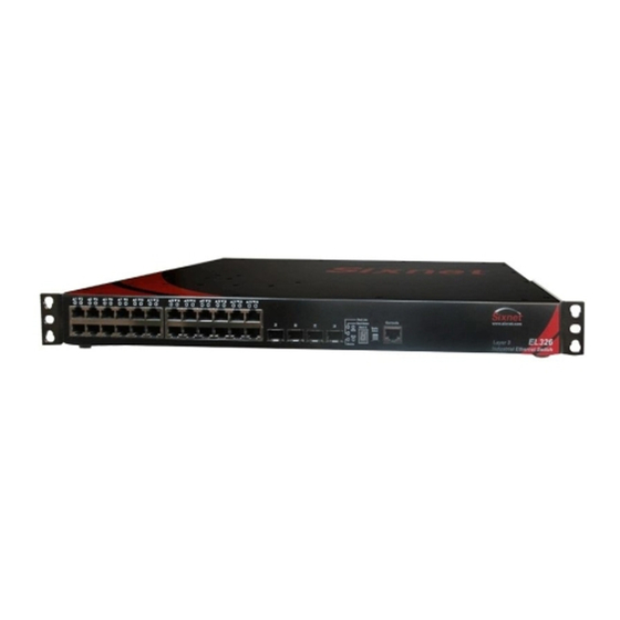
- Page 3 Management Guide Installation Guide Industrial Ethernet Switch Layer 3 with 26 Ports: 20 10/100/1000BASE-T Ports 4 Combination 10/100/1000 SFP Ports 2 10GB Expansion Ports 2 high-speed stacking ports EL326 Installation Guide Rev 10-Feb-14 Page 3 of 33...
-
Page 4: About This Guide
The following publication details the software features of the switch, including the Web interface, CLI and much more: EL326 Management Guide Also, as part of the switch’s software, there is an online web-based help that describes all management related features. - Page 5 (or any other solid-state device) should ever be designed to be responsible for the maintenance of consequential equipment or personnel safety. In particular, Red Lion disclaims any responsibility for damages, either direct or consequential, that result from the use of this equipment in any application.
- Page 6 être conçus pour être responsable de l'entretien de l'équipement consécutifs ou la sécurité du personnel. En particulier, Red Lion décline toute responsabilité pour les dommages, directs ou indirects, résultant de l'utilisation de cet équipement dans n'importe quelle application. Tout courant, câblage entrée et sortie (I / O) doit être conforme aux méthodes de câblage à...
-
Page 7: Fcc Statement
Notice: Shielded interface cable must be used in order to comply with emission limits. Notice: Changes or modification not expressly approved by the party responsible for compliance could void the user’s authority to operate the equipment. EL326 Installation Guide Rev 10-Feb-14 Page 7 of 33... -
Page 8: Industry Canada Statement
This device must accept any interference received, including interference that may cause undesired operation. ce dispositif peut ne pas causer l'interférence nocive, et ce dispositif doit accepter n'importe quelle interférence reçue, y compris l'interférence qui peut causer l'opération peu désirée. EL326 Installation Guide Rev 10-Feb-14 Page 8 of 33... -
Page 9: Warranty Statement
Lion's liability shall not exceed the price of the individual units, which are the basis of the claim. In no event shall Red Lion be liable for any loss of profits, loss of use of facilities or equipment, or other indirect, incidental or consequential damages. -
Page 10: Table Of Contents
Section 5 2. Communication Ports Wiring Page 22 Section 6 LED Indicators Page 26 Section 7 Technical Specifications Page 28 Section 8 Hi-Pot Testing Page 30 Section 9 Service Information Page 32 EL326 Installation Guide Rev 10-Feb-14 Page 10 of 33... -
Page 11: General Information
Section 1 General Information The Red Lion EL326 is a 26 port industrial Ethernet managed switch designed to meet the Overview extreme requirements of power substations, traffic control, railway and other harsh environments. It combines the high performance and security of an enterprise-class switch with rugged packaging and protected circuitry to meet the needs of the most demanding applications. - Page 12 WEEE compliance These devices comply with the WEEE directive. Do not throw away these devices in the standard trash. Contact Red Lion regarding proper disposal. RoHS compliance These devices comply with the RoHS directive and are considered lead and other hazardous substance free.
-
Page 13: Installation And Mounting
Make sure to read Section 3 regarding thermal considerations before installing your switch. The above image shows an EL326 in front style arrangement (ports in front and power in the back) mounted in a typical 19” rack, prior to wiring. - Page 14 For the most durable mounting you can use two brackets on each side (as shown in the image above). This is ideal for applications requiring the highest shock and vibration resistance. EL326 Installation Guide Rev 10-Feb-14 Page 14 of 33...
- Page 15 (set of 2) (set of 2) Optional 23” bracket Optional 23/24” bracket Part #: EK1-BRCKT-23 Part #: EK1-BRCKT-2324 (set of 2) (set of 2) Optional wall bracket Part #: EK1-BRCKT-WALL (set of 2) EL326 Installation Guide Rev 10-Feb-14 Page 15 of 33...
- Page 16 Note: AutoCAD and other drawings are available on the CD or at: www.redlion.net Mechanical Dimensions for the EL326 and Brackets EL326 Installation Guide Rev 10-Feb-14 Page 16 of 33...
-
Page 17: Thermal Considerations
Section 3 Thermal Considerations The EL326 switches are designed to operate from -35 to +80˚C when they are installed Overview properly. The switch is cooled via conduction and radiation. There are no fans. Instead there are various heat-sinks inside the switch to conduct the heat from the components to the heavy- gauge aluminum case. -
Page 18: Section 4 1. Power And Output Wiring
P1 input and supply. Only if P1 fails is power drawn from the P2 backup input and supply. Note: These default modes of operations can be changed at the factory. Contact Red Lion for details. - Page 19 For the highest electrical safety the EL326 switches are provided with several grounding Safety points. First, there are two green ground Grounding Two #10-32 Screws screws (see images) that attach directly to the switch case. These screws can be used for NEBS Compliant to provide a NEBS compliant safety ground.
- Page 20 The “D” option power inputs are reverse polarity protected. This means that if you swap the Reverse Polarity + and – leads then the switch will not be damaged. However, the switch will not operate Protection when wired this way. EL326 Installation Guide Rev 10-Feb-14 Page 20 of 33...
- Page 21 A switch or circuit-breaker must be included in the installation. 2. The switch or circuit-breaker must be suitably located and easily reached. 3. The switch or circuit-breaker must be marked as the disconnecting device for the equipment. EL326 Installation Guide Rev 10-Feb-14 Page 21 of 33...
-
Page 22: Section 5 2. Communication Ports Wiring
RJ45 (copper) Ethernet ports, SFP (pluggable) Ethernet ports and console (serial RS232) ports. The EL326 has 24 Gigabit RJ45 copper ports that accept 10/100/1000 Mbps twisted pair Gig RJ45 cabling. Use data-quality (not voice-quality) twisted pair cable rated category 5E (or better) Ports 1-24 with standard RJ45 connectors. - Page 23 The RJ45 ports will auto-sense for Full or Half duplex operation, while the fiber ports default to Duplex full duplex operation or can be configured for Full or Half duplex. Refer to the software user Operation manual for details on the software configuration options. EL326 Installation Guide Rev 10-Feb-14 Page 23 of 33...
- Page 24 “ring” or “closed-loop.” The closed- loop cable provides a redundant path for the stack link, so if one link fails, stack communications can still be maintained. EL326 Installation Guide Rev 10-Feb-14 Page 24 of 33...
- Page 25 6. The Module LED on the switch’s front panel should turn green to confirm that the module is correctly installed and ready to use. EL326 Installation Guide Rev 10-Feb-14 Page 25 of 33...
-
Page 26: Led Indicators
Section 6 LED Indicators The EL326 switches have: Overview 1 Communication LED for each port 3 Power LEDs (P1, P2 and PWR) 1 “OK” output LED 1 Diagnostic LED 1 Stack Link LED 1 Stack Master LED ... - Page 27 System in Master arbitration/election state. System in standalone mode. An expansion module is installed and operating normally. Green Module LED Amber An expansion module is installed but has failed. There is no module installed. EL326 Installation Guide Rev 10-Feb-14 Page 27 of 33...
-
Page 28: Technical Specifications
Section 7 Technical Specifications These specifications are subject to change. Contact Red Lion for the latest details. Refer to the Technical software user manual or datasheet for complete software specifications. Specs ETHERNET PERFORMANCE SECURITY 26 total Ethernet ports plus 2 expansion bays Enable / disable ports ... - Page 29 Safety: UL508 /ANSI / ISA12.12.01 / CSA C22.2 No. 1U rack mount (19” brackets included) 142 and No. 213 Optional 23”, 24", EIA, WECO, ETSI and wall UL temperature specs: EL326-AA/AO-1, T4 @ 80C brackets available EL326-DD/DO-1, T4 @ +75C ...
-
Page 30: Hi-Pot Testing
Hi-Pot Test Step 2 A. Contact Red Lion and ask to be sent a complimentary “hi-pot slot card”. B. Use a credit-card-sized plastic card (without raised lettering so not an actual credit card), laminated business card or other similar plastic card. The dimensions should be as shown in the diagram below. - Page 31 Caution: Make sure to remove the card when you are done testing. If you leave the card in place during normal operations then your switch will not be fully protected from surges. EL326 Installation Guide Rev 10-Feb-14 Page 31 of 33...
-
Page 32: Service Information
To obtain support for Red Lion products: Product Support Latest product info: http://www.redlion.net Phone: 1-877-432-9908 Fax: 1-518-877-8346 E-mail: support@redlion.net Address: Red Lion Controls • 20 Willow Springs Circle • York • PA • 17406 • USA EL326 Installation Guide Rev 10-Feb-14 Page 32 of 33... - Page 33 This page intentionally left blank. EL326 Installation Guide Rev 10-Feb-14 Page 33 of 33...
Need help?
Do you have a question about the EL326 and is the answer not in the manual?
Questions and answers