
Related Manuals for red lion 308FX2


Summary of Contents for red lion 308FX2
- Page 1 ® N-Tron Series 308FX2, 309FX, 316TX, 317FX Industrial Ethernet Switches User Guide | December 2015...
-
Page 2: Contact Information
20 Willow Springs Circle York, PA 17406 All rights reserved. Red Lion, the Red Lion logo and N-Tron are registered trademarks of Red Lion Controls, Inc. All other company and product names are trademarks of their respective owners. CONTACT INFORMATION: AMERICAS York, PA: +1 (717) 767-6511... -
Page 3: Table Of Contents
. . . . . . . . . . . . . . . . . . . . . . . . . . . . . . . . . . . . . . . . . . . . . . . . . . . . . . . . . . . . . . . . . vi Electrical Safety Warnings / Avertissements de sécurité électrique . . . . . . . . . . . . . . . . . . . . . . . vii Environmental Safety Cautions and Warnings / Sécurité environnementale mises en garde et avertissements . . . . . . . . . . . . . . . . . . . . . . . . . . . . . . . . . . . . . . . . . . . . . . . . . . . viii UL/cUL Hazardous Location Warning / UL/cUL Avertissement d'emplacement dangereux . . . . . . . . . . . . . . . . . . . . . . . . . . . . . . . . . . . . . . . . . . . . . . . . . . . . . . . . . . . . . . . . . . . . . . . . . . viii Laser Safety Warning / Consignes de sécurité relatives au laser . . . . . . . . . . . . . . . . . . . . . . . . . . ix Introduction and Specifications Section 1 . . . . . . . . . . . . . . . . . . . . . . . . . . . . . . . . . . . . . . . . . . . . . . . . . . . . . . . . . 1‐1 Introduction . . . . . . . . . . . . . . . . . . . . . . . . . . . . . . . . . . . . . . . . . . . . . . . . . . . . . . . . . . . . . . . . . . . . . . . . . . . . . . . . . . . 1‐1 308FX2 and 308FXE2 . . . . . . . . . . . . . . . . . . . . . . . . . . . . . . . . . . . . . . . . . . . . . . . . . . . . . . . . . . . . . . . . . . . 1‐1 316TX . . . . . . . . . . . . . . . . . . . . . . . . . . . . . . . . . . . . . . . . . . . . . . . . . . . . . . . . . . . . . . . . . . . . . . . . . . . . . . . . . . 1‐1 309FX and 317FX . . . . . . . . . . . . . . . . . . . . . . . . . . . . . . . . . . . . . . . . . . . . . . . . . . . . . . . . . . . . . . . . . . . . . . . 1‐1 309FXE and 317FXE . . . . . . . . . . . . . . . . . . . . . . . . . . . . . . . . . . . . . . . . . . . . . . . . . . . . . . . . . . . . . . . . . . . . 1‐1 Key Features . . . . . . . . . . . . . . . . . . . . . . . . . . . . . . . . . . . . . . . . . . . . . . . . . . . . . . . . . . . . . . . . . . . . . . . . . . . . . . . . . . . 1‐2 Key Specifications . . . . . . . . . . . . . . . . . . . . . . . . . . . . . . . . . . . . . . . . . . . . . . . . . . . . . . . . . . . . . . . . . . . . . . . . . . . . . . 1‐3 Regulatory Approvals . . . . . . . . . . . . . . . . . . . . . . . . . . . . . . . . . . . . . . . . . . . . . . . . . . . . . . . . . . . . . . . . . . . . . . . . . . 1‐7 Safety . . . . . . . . . . . . . . . . . . . . . . . . . . . . . . . . . . . . . . . . . . . . . . . . . . . . . . . . . . . . . . . . . . . . . . . . . . . . . . . . . . 1‐7 EMI ... - Page 4 Table of Contents Revised 2015-12-04 Installation Section 2 . . . . . . . . . . . . . . . . . . . . . . . . . . . . . . . . . . . . . . . . . . . . . . . . . . . . . . . . . . . . . . . . . . . . . . . . . . . . . . 2‐9 Introduction . . . . . . . . . . . . . . . . . . . . . . . . . . . . . . . . . . . . . . . . . . . . . . . . . . . . . . . . . . . . . . . . . . . . . . . . . . . . . . . . . . . 2‐9 Unpacking . . . . . . . . . . . . . . . . . . . . . . . . . . . . . . . . . . . . . . . . . . . . . . . . . . . . . . . . . . . . . . . . . . . . . . . . . . . . . . . . . . . . . 2‐9 Inspection . . . . . . . . . . . . . . . . . . . . . . . . . . . . . . . . . . . . . . . . . . . . . . . . . . . . . . . . . . . . . . . . . . . . . . . . . . . . . . . . . . . . . 2‐9 Installing/Mounting . . . . . . . . . . . . . . . . . . . . . . . . . . . . . . . . . . . . . . . . . . . . . . . . . . . . . . . . . . . . . . . . . . . . . . . . . . . . 2‐9 ATEX Installation Requirements . . . . . . . . . . . . . . . . . . . . . . . . . . . . . . . . . . . . . . . . . . . . . . . . . . . . . . . . 2‐10 DIN‐Rail Mounting . . . . . . . . . . . . . . . . . . . . . . . . . . . . . . . . . . . . . . . . . . . . . . . . . . . . . . . . . . . . . . . . . . . . 2‐11 Panel and Rack Mounting . . . . . . . . . . . . . . . . . . . . . . . . . . . . . . . . . . . . . . . . . . . . . . . . . . . . . . . . . . . . . 2‐11 Connections . . . . . . . . . . . . . . . . . . . . . . . . . . . . . . . . . . . . . . . . . . . . . . . . . . . . . . . . . . . . . . . . . . . . . . . . . . . . . . . . . . 2‐12 Power Connection (Side View) . . . . . . . . . . . . . . . . . . . . . . . . . . . . . . . . . . . . . . . . . . . . . . . . . . . . . . . . . 2‐12 300 TX/FX Models Grounding Techniques . . . . . . . . . . . . . . . . . . . . . . . . . . . . . . . . . . . . . . . . . . . . . 2‐13 RJ45 Connector Crimp Specifications . . . . . . . . . . . . . . . . . . . . . . . . . . . . . . . . . . . . . . . . . . . . . . . . . . 2‐14 Connecting the Unit . . . . . . . . . . . . . . . . . . . . . . . . . . . . . . . . . . . . . . . . . . . . . . . . . . . . . . . . . . . . . . . . . . . . . . . . . . .
-
Page 5: Preface
While every effort has been made to ensure that this document is complete and accurate at the time of release, the information that it contains is subject to change. Red Lion Controls is not responsible for any additions to or alterations of the original document. -
Page 6: Environmental Impact Statement
Revised 2015-12-04 Environmental Impact Statement Red Lion equipment contains no hazardous materials as defined by the United States Environmental Protection Agency (USEPA). Red Lion recommends that all failed product be returned to Red Lion for failure analysis and proper disposal. Toxic Emissions Red Lion equipment releases no toxic emissions. - Page 7 Ordering Guide Part Number Description Eight port - six 10/100BaseTX RJ-45 ports and two 100BaseFX multimode fiber ports 308FX2-N-XX with ST or SC connectors Eight port - six 10/100BaseTX RJ-45 ports and two 100BaseFX singlemode 15km, 40km 308FXE2-N-XX-YY or 80km fiber ports with ST or SC connectors...
-
Page 8: Release Notes And Document Updates
As needed, Documentation Notes and/or Product Bulletins will be provided between major releases to describe any new information or document changes. The latest online version of this document and all product updates can be accessed through the Red Lion web site http://www.redlion.net Publication History... -
Page 9: Electrical Safety Warnings / Avertissements De Sécurité Électrique
CAUTION: Do not operate the equipment in a manner not specified by this manual. ATTENTION: Ne pas faire fonctionner l'équipement d'une manière non spécifiée par ce manuel. CAUTION: If the equipment is used in a manner not specified by Red Lion, the protection provided by the equipment may be impaired. -
Page 10: Environmental Safety Cautions And Warnings / Sécurité Environnementale Mises En Garde Et Avertissements
Preface Revised 2015-12-04 WARNING: Do not operate the unit with the top cover removed. AVERTISSEMENT : Ne pas faire fonctionner l'unité avec le capot retiré. CAUTION: Observe proper DC Voltage polarity when installing power input cables. Reversing volt- age polarity can cause permanent damage to the unit and voids the warranty. ATTENTION: Respecter la polarité... -
Page 11: Laser Safety Warning / Consignes De Sécurité Relatives Au Laser
Preface Revised 2015-12-04 CAUTION: Class I, Division 2 installations require that all devices connected to this product must be UL listed for the area in which it is installed. ATTENTION: Classe I, division 2 installations nécessitent que tous les périphériques connectés à ce produit doit être homologué... - Page 12 Preface Revised 2015-12-04 N-Tron® Series 300 TX/FX Models User Guide...
-
Page 13: Introduction And Specifications
308FX2 and 308FXE2 The 308FX2 is an affordable 8 port switch that has 6 copper ports plus two additional multimode fiber optic up-link ports. The two fiber links are capable of 2 Kilometers of 100 Mb communications without the use of repeaters.The 308FXE2 is similar to the 308FX2, but is populated with singlemode extended range fiber optics. -
Page 14: Key Features . . . . . . . . . . . . . . . . . . . . . . . . . . . . . . . . . . . . . . . . . . . . . . . . . . . . . . . . . . . . . . . . . . . . . . . . . . . . . . . . . . . 1-2
Introduction and Specifications Revised 2015-12-04 Key Features Full IEEE 802.3 & 100Base-FX Compliance • Full IEEE 1613 Compliance (Communications Networking Devices in Electric Power Stations) • American Bureau of Shipping (ABS) Type Approval (Maritime and Offshore Applications) • Extended Environmental Specifications •... -
Page 15: Key Specifications . . . . . . . . . . . . . . . . . . . . . . . . . . . . . . . . . . . . . . . . . . . . . . . . . . . . . . . . . . . . . . . . . . . . . . . . . . . . . . 1-3
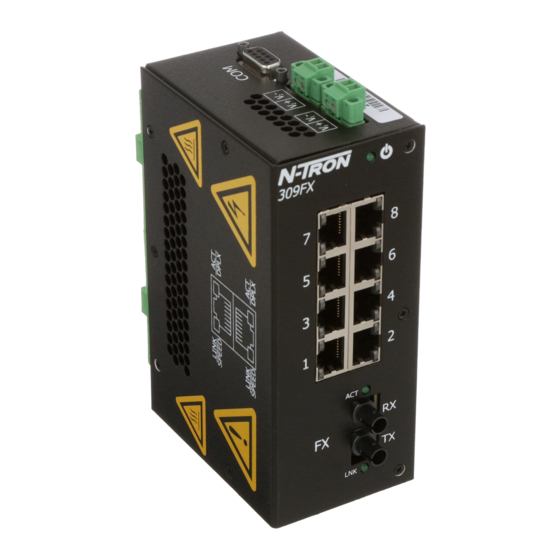
Introduction and Specifications Revised 2015-12-04 Key Specifications Table 2. 308FX2/FXE2 Key Specifications Switch Properties # of MAC Addresses Aging Time Latency Minimum Backplane Speed Switching Method 4,000 Programmable 2.2 μs 2.6 Gb/s Store & Forward Physical Height Width Depth Weight DIN-Rail 5.9 in (15cm) 2.3 in (5.8cm) - Page 16 Introduction and Specifications Revised 2015-12-04 Table 3. 309FX/FXE Key Specifications Switch Properties # of MAC Addresses Aging Time Latency Minimum Backplane Speed Switching Method 4,000 Programmable 2.2 μs 2.6 Gb/s Store & Forward Physical Height Width Depth Weight DIN-Rail 5.5 in (13.9cm) 2.3 in (5.8cm) 3.5 in (8.9cm) 1.6 lbs (0.8kg)
- Page 17 Introduction and Specifications Revised 2015-12-04 Table 4. 316TX Key Specifications Switch Properties # of MAC Addresses Aging Time Latency Minimum Backplane Speed Switching Method 4,000 Programmable 2.2 μs 2.6 Gb/s Store & Forward Physical Height Width Depth Weight DIN-Rail 7.4 in (18.8cm) 2.3 in (5.8cm) 3.5 in (8.9cm) 1.9 lbs (0.9 kg)
- Page 18 Introduction and Specifications Revised 2015-12-04 Table 5. 317FX/FXE Key Specifications Switch Properties # of MAC Addresses Aging Time Latency Minimum Backplane Speed Switching Method 4,000 Programmable 2.2 μs 2.6 Gb/s Store & Forward Physical Height Width Depth Weight DIN-Rail 7.4 in (18.8cm) 2.3 in (5.8cm) 3.5 in (8.9cm) 1.9 lbs (0.9kg)
-
Page 19: Regulatory Approvals . . . . . . . . . . . . . . . . . . . . . . . . . . . . . . . . . . . . . . . . . . . . . . . . . . . . . . . . . . . . . . . . . . . . . . . . . . 1-7
Introduction and Specifications Revised 2015-12-04 Table 6. Fiber Transceiver Characteristics FX/FXE Models Fiber Length 2km* 15km** 40km** 80km** -19dBm -15dBM -5dBm -5dBm TX Power Minimum -31dBm -31dBm -34dBm -34dBm RX Sensitivity Maximum 1310nm 1310nm 1310nm 1550nm Wavelength * = Multimode **= Singlemode Regulatory Approvals Safety Suitable for use in Class I, Division 2, Groups A, B, C and D Hazardous Locations, or Nonhazardous Locations only. - Page 20 Introduction and Specifications Revised 2015-12-04 Certifications GOST-R Certified N-Tron® Series 300 TX/FX Models User Guide...
-
Page 21: Unpacking . . . . . . . . . . . . . . . . . . . . . . . . . . . . . . . . . . . . . . . . . . . . . . . . . . . . . . . . . . . . . . . . . . . . . . . . . . . . . . . . . . . . . 2-9
Remove all the equipment from the packaging, and store the packaging in a safe place. Inspection Please ensure the shipping package contains the following items in undamaged condition: 1. 308FX2, 309FX, 316TX, or 317FX switch. 2. Product CD If the package contents are damaged: 1. -
Page 22: Atex Installation Requirements
Installation Revised 2015-12-04 WARNING: Disconnect the power cable before removing the enclosure top. AVERTISSEMENT: Débranchez le câble d'alimentation avant de retirer le boîtier supérieur. WARNING: Do not operate the unit with the top cover removed. AVERTISSEMENT : Ne pas faire fonctionner l'unité avec le capot retiré. ATEX Installation Requirements This section provides guidance for an installation to meet ATEX certification requirements.... -
Page 23: Din-Rail Mounting
Installation Revised 2015-12-04 DIN‐Rail Mounting ‐ 308FX2 and 309FX Install the unit on a standard 35mm DIN-Rail. Recess the 308FX2/309FX unit to allow at least 5” of horizontal clear- ance for fiber optic cable bend radius. Vertical Mounting 1. To mount the unit vertically to the 35mm DIN-Rail, place the top edge of the bracket on the back of the unit against the DIN-Rail's top edge at an upward angle. - Page 24 Installation Revised 2015-12-04 DIN‐Rail Mounting ‐ 316TX and 317FX Install the unit on a standard 35mm DIN-Rail. Recess the 316TX unit to allow at least 3” of horizontal clearance for copper cable bend radius. Recess the 317FX unit to allow at least 5” of horizontal clearance for fiber cable bend radius.
-
Page 25: Connections
Installation Revised 2015-12-04 Optional Mounting Most N-Tron® series products are designed to be mounted on industry standard 35mm DIN-Rail. However, DIN- Rail mounting may not be suitable for all applications. The Universal Rack Mount Kit (P/N: URMK), shown in the figure below, may be used to mount the 316TX/317FX unit to standard 19” racks as an option. Connections Power Connection (Side View) 1. -
Page 26: 300 Tx/Fx Models Grounding Techniques
Installation Revised 2015-12-04 300 TX/FX Models Grounding Techniques The grounding philosophy of any control system is an integral part of the design. N-Tron series switches are designed to be grounded, but the user has been given the flexibility to float the switch when required. The best noise immunity and emissions (i.e. -
Page 27: Rj45 Connector Crimp Specifications
Installation Revised 2015-12-04 RJ45 Connector Crimp Specifications Please reference the illustration below for the Cat5 cable specifications: Connecting the Unit For FX/FXE units, remove the dust cap from the fiber optic connectors and connect the fiber optic cables. The TX port on the FX/FXE models should be connected to the RX port of the far end station. The RX port on the FX/FXE models should be connected to the TX port of the far end station. -
Page 28: Serial Interface
Serial Cable Connect the serial COM port of your PC and the 308FX2/309/316/317 switch using a standard straight through cable. You will require a cable with a 9-pin or 25-pin sub-D female connector for the PC end, and a 9-pin male sub- D connector for the 308FX2/309/316/317 end. -
Page 29: Operation And Maintenance
Operation and Maintenance Revised 2015-12-04 Section 3 Operation and Maintenance Introduction This section provides information on the 300 TX/FX models device ports and LED indicators function, device operation, and basic maintenance and troubleshooting guidelines. 300 TX/FX Models Ports and Indicators The 300 TX/FX models ports and LED indicators, and a description of their functions, are identified in Table Table 9. -
Page 30: 300 Tx/Fx Models Led's And Operating Modes
(marked COM). To access the CLI 1. Connect a PC serial port to the 308FX2/309/316/317 V24 serial port and use HyperTerminal or equivalent. 2. Set COM Parameters to: 9600, 8, none, 1, none 3. After a successful connection and reboot, the boot menu should display: 4. -
Page 31: Logging In (Password Protection)
316/317 switch parameters. Note: The admin password is admin. 1. On a 308FX2 switch, you must first press <Escape> to access the Management Console Function. 2. Login: enter username ‘admin’ and press <Enter>. 3. Password: enter password ‘admin’ and press <Enter>. -
Page 32: Cli Navigation
• full (Force full duplex for each port) • crossover (Force crossover connection for each port) • filters (Select traffic filter(s)) ‘filters’ are on 308FX2 only • info (Get info on Filters) • dis_nring (Disable filters for N-Ring) • (or ‘en_nring’ if currently disabled) dis_ring600 (Disable filters for 600 ring)... -
Page 33: Home Menu
N-View function is enabled Info Displays the current system status. or (info for 308FX2/309) LINK Status, Rate, Flow, etc. info1, info2... (Info1, 2 for 316/317) Restores the default settings of the Restores factory settings of the switch. With the Restore switch (complete reset).... -
Page 34: N-View™ Menu
Note: With the ‘-N’ option all ports have N-View ‘enabled’ in defaults, but can be it can be disabled. Rate for generation of MIB information frames is ~6.4 seconds. The FX Port is mapped to port 9 on the 309, and as port 17 on the 317. On the 308FX2, ports 7 and 8 are FX ports. -
Page 35: System Info Menu
All RJ45 ports are set to auto-MDIX (as opposed to enabling crossover only). • N-View is enabled on –N units. ™ • On the 308FX2, both ring filters are enabled. • unaffected by The MAC address, model number, and firmware version are protected settings. These settings are restoring factory defaults. Switch Menu... -
Page 36: Ports Commands
If one end of a link is set to forced speed/duplex, but the other end is not forced, problems can be created. On the 308FX2, 309, 316, or 317, it is possible to autonegotiate, or force to any of 4 modes: 100 full, 100 half, 10 full, or 10 half. - Page 37 Operation and Maintenance Revised 2015-12-04 Refer to the screens that follow for examples of executing each port command. N-Tron® Series 300 TX/FX Models User Guide 3-25...
-
Page 38: Filters Commands
Operation and Maintenance Revised 2015-12-04 Filters Commands On the 308FX2 only, filters are provided and enabled in defaults to keep ring control frames only on the ring ports. The available “filters” commands are described in Table Table 17. Filters Commands Command Description Comment en_nring, or... - Page 39 There are no user serviceable parts inside the unit. Removing the top cover will void the warranty. N‐Tron® Series 300 TX/FX Models Limited Warranty a) Red Lion Controls Inc., Sixnet Inc., N-Tron Corporation, or Blue Tree Wireless Data, Inc. (the “Company”) war- rants that all Products shall be free from defects in material and workmanship under normal use for the period of time provided in “Statement of Warranty Periods”...
- Page 40 Operation and Maintenance Revised 2015-12-04 3-28 N-Tron® Series 300 TX/FX Models User Guide...
Need help?
Do you have a question about the 308FX2 and is the answer not in the manual?
Questions and answers