
Related Manuals for red lion EL228


Summary of Contents for red lion EL228
-
Page 1: Installation Guide
EL228 Industrial Ethernet Managed Switch Installation Guide Revision: 16 January 2014 www.redlion.net... - Page 2 This page intentionally left blank. EL228 Installation Guide Rev 16-Jan-14 Page 2 of 34...
- Page 3 2 Combination Gigabit (RJ45/SFP) Ports Included with the switch (typically): 19” Brackets & Screws Screw Plugs CD with: Manuals SFP Plugs Drawings And more Quick Start Guide EL228 Installation Guide Rev 16-Jan-14 Page 3 of 34...
-
Page 4: About This Guide
The following publication details the software features of the switch, including the Web interface, CLI and much more: EL228 Management Guide Also, as part of the switch’s software, there is an online web-based help that describes all management related features. - Page 5 These products are suitable for use in Class I, Division 2, Groups A, B, C and D hazardous locations or nonhazardous locations only. Note: Only the EL228-DD-1 and the EL228-D0-1 are approved for Zone 2 (ATEX) areas.
- Page 6 Cet appareil est adapté pour utilisation de Classe I, Division 2, Groupes A, B, C, D endroits dangereux ou endroits non-dangereux. Note: Seulement les EL228-DD-1 et EL228-D0-1 sont approuvés pour les endroits Zone 2 (ATEX). ...
- Page 7 2000 VAC or 2800 VDC (1 minute), or 2400 VAC or 3300 VDC (1 second) according to IEEE 1613. However, the surge circuitry must be bypassed before performing this test. See section 8 for details. Power Markings Direct Current (DC) Alternating Current Protective Conductor Terminal EL228 Installation Guide Rev 16-Jan-14 Page 7 of 34...
-
Page 8: Fcc Statement
This device must accept any interference received, including interference that may cause undesired operation. Ce dispositif peut ne pas causer l’interférence nocive et Ce dispositif doit accepter n’importe quelle interférence reçue, y compris l’interférence qui peut causer l’opération peu désirée. EL228 Installation Guide Rev 16-Jan-14 Page 8 of 34... -
Page 9: Warranty Statement
Lion's liability shall not exceed the price of the individual units, which are the basis of the claim. In no event shall Red Lion be liable for any loss of profits, loss of use of facilities or equipment, or other indirect, incidental or consequential damages. -
Page 10: Table Of Contents
Page 22 Section 6 LED Indicators Page 27 Section 7 Reset Button Page 28 Section 8 Hi-Pot Testing Page 29 Section 9 Technical Specifications Page 31 Section 10 Service Information Page 33 EL228 Installation Guide Rev 16-Jan-14 Page 10 of 34... -
Page 11: General Information
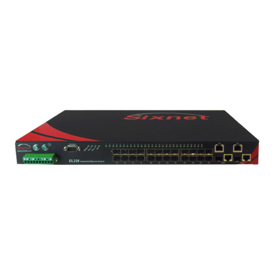
Section 1 General Information The Red Lion EL228 is a 28 port (24 + 4G) industrial Ethernet managed switch designed to Overview meet the extreme requirements of power substations, traffic control, railway and other harsh environments. It combines the high performance and security of an enterprise-class switch with rugged packaging and protected circuitry to meet the needs of the most demanding applications. - Page 12 CE per Low Voltage Directive and EN/IEC 61010-1 UL508 (Industrial control equipment ), ANSI / ISA12.12.01 (Hazardous Locations) CSA C22.2 142/213 (per cUL) Zone 2 (ATEX), Only EL228-DD-1 and EL228-D0-1 are approved for Zone 2 (ATEX) areas. EMC (emissions and immunity) ...
-
Page 13: Installation And Mounting
Make sure to read Section 3 regarding thermal considerations before installing your switch. The above image shows an EL228 in front style arrangement (ports in front and power in the back) mounted in a typical 19” rack, prior to wiring. - Page 14 For the most durable mounting you can use two brackets on each side (as shown in the image above). This is ideal for applications requiring the highest shock and vibration resistance. EL228 Installation Guide Rev 16-Jan-14 Page 14 of 34...
- Page 15 (set of 2) (set of 2) Optional 23” bracket Optional 23/24” bracket Part #: EK1-BRCKT-23 Part #: EK1-BRCKT-2324 (set of 2) (set of 2) Optional wall bracket Part #: EK1-BRCKT-WALL (set of 2) EL228 Installation Guide Rev 16-Jan-14 Page 15 of 34...
-
Page 16: Industrial Ethernet
[31.8] ETSI 22.32" [566.9] 23.90" [607.1] 1.00" WECO [25.4] 1.25" With 23/24" Brackets (optional) (Universal EiA/WECO/ETSI mounting holes) [31.8] ETSI 22.32" [566.9] 23.32" [592.3] Mechanical Dimensions for the EL228 and Brackets EL228 Installation Guide Rev 16-Jan-14 Page 16 of 34... -
Page 17: Thermal Considerations
Section 3 Thermal Considerations The EL228 switches are designed to operate from -40 to +85˚C when they are installed Overview properly. The switch is cooled via conduction and radiation. There are no fans. Instead there are various heat-sinks inside the switch to conduct the heat from the components to the heavy- gauge aluminum case. -
Page 18: Power And Output Wiring
Otherwise, there is a risk of electrical shock if the rules and warnings in this manual are not properly adhered too. The EL228 switches are offered with several power options including dual power supplies Power that can keep the switch running when there is a power input failure or internal power Overview supply failure. - Page 19 The EL228 features Universal Mounting (Patent Pending) that allows the power to be Universal connected to either the front or the back of the switch. The EL228 has power input headers Mounting on both sides, and is supplied with one power plug (typically pre-installed on the port side) and one power cover (installed on the opposite side).
- Page 20 The “D” option power inputs are reverse polarity protected. This means that if you swap the Reverse Polarity + and – leads then the switch will not be damaged. However, the switch will not operate Protection when wired this way. EL228 Installation Guide Rev 16-Jan-14 Page 20 of 34...
- Page 21 24 to 14 AWG. When tightening the screws be careful to tighten to a maximum Screw Torque torque of 4.5 in/lb (0.51 Nm). We recommend a minimum of 18 AWG for the input power wires. EL228 Installation Guide Rev 16-Jan-14 Page 21 of 34...
-
Page 22: Communication Wiring
RJ45 (copper) Ethernet ports, SFP (pluggable) Ethernet ports and console (serial RS232) ports. The EL228 has four Gigabit RJ45 copper ports (25-28) that accept 10/100/1000 Mbps twisted Gig RJ45 pair cabling. Use data-quality (not voice-quality) twisted pair cable rated category 5E (or better) Ports 25-28 with standard RJ45 connectors. - Page 23 To remove a transceiver, first pull down on the locking/release arm and then pull the transceiver out. The transceivers are “hot-swappable” meaning they can be plugged in or removed when the switch is powered. EL228 Installation Guide Rev 16-Jan-14 Page 23 of 34...
- Page 24 WDM and other special types. They typically are offered with an LC style fiber connector. Refer to the datasheets for these transceivers for more details. Typical Fiber SFP Transceiver and Dual-LC Cable EL228 Installation Guide Rev 16-Jan-14 Page 24 of 34...
- Page 25 This manual only details on how to connect to this port. Refer to the software manual for details on how to configure the switch via this port. RS232 DB9M Ports (one on each side) RS232 Pin 6 DB9M Pin 1 RS232 DB9M Port Closeup EL228 Installation Guide Rev 16-Jan-14 Page 25 of 34...
- Page 26 CD in modem Cable RD in RD in TD out TD out DTR out DTR out DSR in DSR in RTS out RTS out CTS in CTS in RI in RI in EL228 Installation Guide Rev 16-Jan-14 Page 26 of 34...
-
Page 27: Led Indicators
Section 6 LED Indicators The EL228 switches have 1 or 2 communication LEDs for each port, dual power LEDs, an Overview “OK” output LED and an overall status LED. LED Location on Port Side LED Location on Other Side All 28 ports each have only 1 LED. Regardless of the type of port (RJ45 versus SFP) or... -
Page 28: Reset Button
To simply perform a hardware reset just push in the reset button momentarily. The switch Hardware will then immediately perform a hardware reset which takes around 2 minutes. The switch Reset will not function or be accessible during this period. EL228 Installation Guide Rev 16-Jan-14 Page 28 of 34... -
Page 29: Hi-Pot Testing
Hi-Pot Test Step 2 A. Contact Red Lion and ask to be sent a complimentary “hi-pot slot card”. B. Use a credit-card-sized plastic card (without raised lettering so not an actual credit card), laminated business card or other similar plastic card. The dimensions should be as shown in the diagram below. - Page 30 Caution: Make sure to remove the card when you are done testing. If you leave the card in place during normal operations then your switch will not be fully protected from surges. EL228 Installation Guide Rev 16-Jan-14 Page 30 of 34...
-
Page 31: Technical Specifications
Section 9 Technical Specifications These specifications are subject to change. Contact Red Lion for the latest details. Refer to Technical the software user manual or datasheet for complete software specifications. Specs ETHERNET PERFORMANCE SECURITY 28 total Ethernet ports Enable / disable ports ... - Page 32 Universal mounting: (Sixnet-exclusive feature – Patent Safety: UL508 / ANSI / ISA12.12.01/CSA C22.2 Pending!) 142/213. EL228-DD-1 and the EL228-D0-1, T4 @ Front or rear/reverse wiring with power in front or 60C (Ambient); EL228-AA-1 and the EL228-A0-1, back T3C @ 60C (Ambient). EN61010-1, Zone 2 (ATEX).
-
Page 33: Service Information
Section 10 Service Information Service We sincerely hope that you never experience a problem with any Red Lion product. If you do need service, call Red Lion at 1-877-432-9908 for Technical Support. A trained specialist will Information help you to quickly determine the source of the problem. Many problems are easily resolved with a single phone call. - Page 34 This page intentionally left blank. EL228 Installation Guide Rev 16-Jan-14 Page 34 of 34...
Need help?
Do you have a question about the EL228 and is the answer not in the manual?
Questions and answers