
Subscribe to Our Youtube Channel
Related Manuals for red lion EL212F


Summary of Contents for red lion EL212F
- Page 1 EL212F Industrial Ethernet Managed Switch Installation Guide Revision: 16 January 2014 www.redlion.net...
- Page 2 This page intentionally left blank. EL212 Installation Guide Rev 16-Jan-14 Page 2 of 28...
- Page 3 Management Guide Installation Guide Industrial Ethernet Switch Layer 2 with 8 + 4G: 8 100BASE-BX (SFP) Ports 2 1000BASE-T (SFP) Ports 2 Combination Gigabit (RJ45/SFP) Ports EL212 Installation Guide Rev 16-Jan-14 Page 3 of 28...
- Page 4 About This Guide Purpose This guide gives specific information on how to properly install and maintain the switch. Audience The guide is intended for use by network administrators who are responsible for installing and setting up network equipment; consequently, it assumes a basic working knowledge of electrical safety and any local, regulatory or corporate rules for the installation of industrial electrical equipment.
- Page 5 In particular, Red Lion disclaims any responsibility for damages, either direct or consequential, that result from the use of this equipment in any application. All power, input and output (I/O) wiring must be in accordance with Class I, Division 2 wiring methods and/or in accordance with the authority having jurisdiction.
- Page 6 Aucun dispositif basé sur un logiciel (ou tout autre dispositif à l'état solide) devraient jamais être conçus pour être responsable de l'entretien de l'équipement consécutifs ou la sécurité du personnel. En particulier, Red Lion décline toute responsabilité pour les dommages, directs ou indirects, résultant de l'utilisation de cet équipement dans n'importe quelle application.
- Page 7 Fiber Optic Safety Warning: When using fiber optic ports, never look at the transmit laser, fiber TX port or fiber cable ends while the switch is powered on. It is highly recommended to keep the rubber fiber plugs inserted when the fiber port is not being used. Hi-Pot (Dielectric) Testing Caution: This device is designed to withstand a high-potential “hi-pot”...
- Page 8 FCC Statement This device complies with Part 15 of the FCC Rules. Operation is subject to the following two conditions: This device may not cause harmful interference. This device must accept any interference received, including interference that may cause undesired operation. Warning: This equipment has been tested and found to comply with the limits for digital device, pursuant to Part 15 of the FCC Rules.
- Page 9 Lion's liability shall not exceed the price of the individual units, which are the basis of the claim. In no event shall Red Lion be liable for any loss of profits, loss of use of facilities or equipment, or other indirect, incidental or consequential damages.
-
Page 10: Table Of Contents
Contents Section 1 General Information Page 11 Section 2 Installation and Mounting Page 13 Section 3 Thermal Considerations Page 15 Section 4 Power and Output Wiring Page 16 Section 5 Communication Wiring Page 19 Section 6 LED Indicators Page 23 Section 7 Reset Button Page 24... -
Page 11: General Information
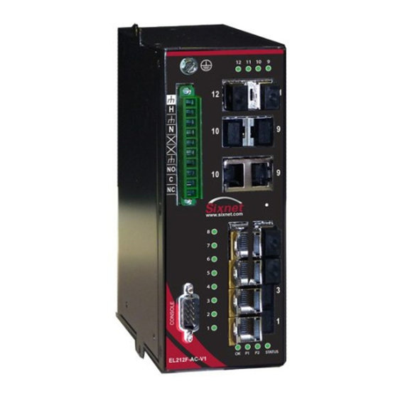
Section 1 General Information The Red Lion EL212 is a 12 port (8 + 4G) industrial Ethernet managed switch designed to Overview meet the extreme requirements of power substations, traffic control, railway and other harsh environments. It combines the high performance and security of an enterprise-class switch with rugged packaging and protected circuitry to meet the needs of the most demanding applications. - Page 12 UL508 (Industrial control equipment) ANSI / ISA12.12.01 (Hazardous Locations) CSA C22.2 No. 142 and No. 213 (per cUL) Zone 2 (ATEX), Only EL212F-DC-V1 is approved for Zone 2 (ATEX) areas. EMC (emissions and immunity) CE per the EMC directive ...
-
Page 13: Installation And Mounting
Section 2 Installation and Mounting Overview Important Note: Make sure to read Section 3 regarding thermal considerations before installing your switch. Important Note: When you are choosing your mounting option make sure to allow enough room to route your Ethernet copper or fiber optic cables. Also, please consult the specifications for your fiber optic cable to make sure you allow for the proper bend radius. - Page 14 Mechanical Dimensions for the EL212 EL212 Installation Guide Rev 16-Jan-14 Page 14 of 28...
-
Page 15: Thermal Considerations
Section 3 Thermal Considerations The EL212 switches are designed to operate from -40 to +85˚C when they are installed Overview properly. The switch is cooled via conduction and radiation. There are no fans. Instead there are various heat-sinks inside and outside the switch to conduct the heat from the components to the heavy-gauge aluminum case. -
Page 16: Power And Output Wiring
Otherwise, you may damage your switch by applying the wrong power. For the highest electrical safety the EL212F switches are provided with several grounding Safety points. First, there are two green ground... - Page 17 The power headers and plugs will be labeled to guide you in properly connecting your Power power. Make sure to reference this labeling when wiring your switch to make sure you are Labeling connecting the appropriate power to the correct terminals. If your switch does not have dual power inputs then do not connect anything to the terminals labeled Power 2.
- Page 18 The switches have an “OK” alarm output that can be tied to a PLC input, an alarm indicator “OK” Alarm (visible or audible) or other device to indicate when there is an alarm condition (such as the Output loss of a power input). The alarm output is a Form C relay with a normally open (NO), normally closed (NC) and common (C) screw terminal.
-
Page 19: Communication Wiring
Section 5 Communication Ports Wiring The EL212 switches provide connections to standard Ethernet devices such as PLCs, Overview Ethernet I/O, industrial computers and much more. Three types of communication ports may be found on these switches: RJ45 (copper) Ethernet ports, SFP (pluggable) Ethernet ports and console (serial RS232) ports. - Page 20 RJ45 Cable The maximum cable length for 10/100/1000BaseT is typically 100 meters (328 ft.). Distance Ports 9 -12 are gigabit ports that provide SFP (Small Form-factor Pluggable) connectors. This Gig SFP allows you to use the RJ45 connectors for twisted pair copper connections or use the SFP Ports 9-12 connectors for fiber optic connections.
- Page 21 Typical Fiber SFP Transceiver and Dual-LC Cable Use standard fiber optic wiring techniques (not covered by this manual) to make your connections. The corresponding LED will be ON solid or flashing when you have made a proper connection. The RJ45 ports will auto-sense for Full or Half duplex operation, while the fiber ports default to Duplex full duplex operation or can be configured for Full or Half duplex.
- Page 22 The switch has a standard RS232 male DB9 serial port as shown in the previous images. Serial DB9 The pin-outs are defined below. Use a standard “null-modem” cable between your PC and Console Port the switch. This cable is not supplied but is available from any computer store. If your PC does not have a serial DB9 port then you can purchase an inexpensive USB to Serial converter from any computer store, or use the USB port on the switch.
-
Page 23: Led Indicators
Otherwise, if it is OFF or flashing for an extended period of time then a problem is detected. In this case, please contact Red Lion for support. There are two Power LEDs (labeled Pwr 1 for primary power and Pwr 2 for backup power) Power LEDs that indicate if there is power applied to the respective input. -
Page 24: Reset Button
Section 7 Reset Button A reset button has been provided in the event that a full hardware reset of the switch is Reset Button required. The reset button is accessed through a small hole in the front of the switch near the status LED. -
Page 25: Technical Specifications
Section 8 Technical Specifications These specifications are subject to change. Contact Red Lion for the latest details. Refer to Technical the software user manual or datasheet for complete software specifications. Specs ETHERNET PERFORMANCE SECURITY 12 total Ethernet ports Enable / disable ports ... - Page 26 Front or rear/reverse wiring with power in front or 142/213. EL212F-DC-V1, T4 @ 85C (Surrounding back Air); EL212F-AC-V1, T3C @ 50C (Surrounding Air). 1U rack mount (19” brackets included) EN61010-1, Zone 2 (ATEX). Only the EL212F-DC-V1 Optional 23”, 24", EIA, WECO, ETSI and wall is approved for Zone 2 (ATEX) areas.
-
Page 27: Service Information
Section 9 Service Information Service We sincerely hope that you never experience a problem with any Red Lion product. If you do need service, call Red Lion at 1-877-432-9908 for Technical Support. A trained specialist will Information help you to quickly determine the source of the problem. Many problems are easily resolved with a single phone call. - Page 28 This page intentionally left blank. EL212 Installation Guide Rev 16-Jan-14 Page 28 of 28...
Need help?
Do you have a question about the EL212F and is the answer not in the manual?
Questions and answers