
Related Manuals for Thermal Arc Fabricator 211i


Summary of Contents for Thermal Arc Fabricator 211i
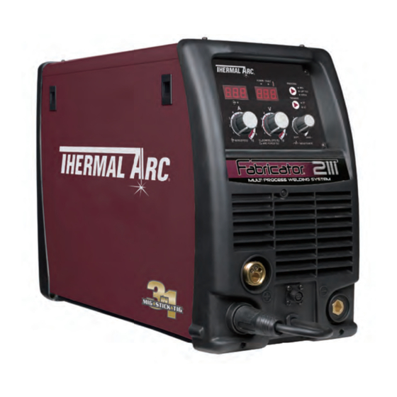
- Page 1 211i FabricatOr ® Multi prOcess welding inverter Operating Manual Art # A-10934 Revision: AB Issue Date: February 29, 2012 Manual No.: 0-5225 Operating Features:...
- Page 2 YOU ARE IN GOOD COMPANY! The Brand of Choice for Contractors and Fabricators Worldwide. Thermal Arc is a Global Brand of Arc Welding Products for Thermadyne Industries Inc. We manufacture and supply to major welding industry sectors worldwide including; Manufacturing, Construction, Mining, Automotive, Aerospace, Engineering, Rural and DIY/Hobbyist.
- Page 3 While the information contained in this Manual represents the Manufacturer’s best judgment, the Manufacturer assumes no liability for its use. Operating Manual Number 0-5225 for: Thermal Arc Fabricator 211i Inverter Power Supply Part Number W1004206 Thermal Arc Fabricator 211i Inverter System...
-
Page 4: Table Of Contents
TABLE OF CONTENTS SECTION 1: SAFETY INSTRUCTIONS AND WARNINGS ............1-1 1.01 Arc Welding Hazards ..................1-1 1.02 Principal Safety Standards ................1-5 1.03 Symbol Chart ....................1-6 1.04 Declaration Of Conformity ................1-7 SECTION 2: INTRODUCTION ................2-1 2.01 How To Use This Manual ................ - Page 5 TABLE OF CONTENTS SECTION 6: KEY SPARE PARTS ................... 6-1 6.01 Power Source Spare Parts ................6-1 APPENDIX: FABRICATOR 211i CIRCUIT DIAGRAM ............ A-1 THERMAL ARC - LIMITED WARRANTY TERMS TERMS OF WARRANTY – JANUARY 2011...
-
Page 7: Safety Instructions And Warnings
SAFETY INSTRUCTIONS FABRICATOR 211i SECTION 1: SAFETY INSTRUCTIONS AND WARNINGS WARNING PROTECT YOURSELF AND OTHERS FROM POSSIBLE SERIOUS INJURY OR DEATH. KEEP CHILDREN AWAY. PACEMAKER WEARERS KEEP AWAY UNTIL CONSULTING YOUR DOCTOR. DO NOT LOSE THESE INSTRUCTIONS. READ OPERATING/INSTRUCTION MANUAL BEFORE INSTALLING, OPERATING OR SERVICING THIS EQUIPMENT. -
Page 8: Safety Instructions
FABRICATOR 211i SAFETY INSTRUCTIONS 2. Wear approved safety glasses. Side shields recommended. 3. Use protective screens or barriers to protect others WARNING from flash and glare; warn others not to watch the ARC RAYS can burn eyes and skin; NOISE arc. - Page 9 SAFETY INSTRUCTIONS FABRICATOR 211i 3. Remove all flammables within 35 ft (10.7 m) of the welding arc. If this is not possible, tightly cover them with approved covers. WARNING 4. Be alert that welding sparks and hot materials from FUMES AND GASES can be hazardous to welding can easily go through small cracks and your health.
- Page 10 FABRICATOR 211i SAFETY INSTRUCTIONS 1. Keep all doors, panels, covers, and guards 5. Use only correct shielding gas cylinders, closed and securely in place. regulators, hoses, and fittings designed for the specific application; maintain them and associated 2. Stop engine before installing or connecting parts in good condition.
-
Page 11: Principal Safety Standards
SAFETY INSTRUCTIONS FABRICATOR 211i NOTE 1.02 Principal Safety Standards Considerations About Welding And The Safety in Welding and Cutting, ANSI Standard Z49.1, Effects of Low Frequency Electric and from American Welding Society, 550 N.W. LeJeune Magnetic Fields Rd., Miami, FL 33126. -
Page 12: Symbol Chart
FABRICATOR 211i SAFETY INSTRUCTIONS 1.03 Symbol Chart Note that only some of these symbols will appear on your model. Wire Feed Function Single Phase Wire Feed Towards Workpiece With Three Phase Output Voltage OFF. Three Phase Static Frequency Converter- Welding Gun... -
Page 13: Declaration Of Conformity
SAFETY INSTRUCTIONS FABRICATOR 211i 1.04 Declaration Of Conformity Manufacturer: Thermadyne Industries Address: 82 Benning Street West Lebanon, New Hampshire 03784 The equipment described in this manual conforms to all applicable aspects and regulations of the ‘Low Voltage Directive’ (European Council Directive 73/23/EEC as amended by Council Directive 93/68/EEC) and to the National legislation for the enforcement of this Directive. - Page 14 FABRICATOR 211i SAFETY INSTRUCTIONS This Page Intentionally Blank SAFETY INSTRUCTIONS AND WARNINGS Manual 0-5225...
-
Page 15: Section 2: Introduction
CAUTION 2.04 Description A CAUTION refers to possible equipment The Thermal Arc Fabricator 211i is a self contained damage. single phase multi process welding inverter that is ca- NOTE pable of performing MIG (GMAW/FCAW), STICK (MMA) and LIFT TIG (GTAW) welding processes. -
Page 16: User Responsibility
1.0/1.2mm "U" groove, This equipment or any of its parts should not be altered from standard specification without prior written ap- 0.8/0.9mm "V" knurled, proval of Thermal Arc. The user of this equipment shall • MIG gun 3m long have the sole responsibility for any malfunction which • Electrode Holder with 4m lead results from improper use or unauthorized modifica- • Work Clamp with 4m lead... -
Page 17: Duty Cycle
(MIG, TIG & STICK) 100 110 120 130 140 150 160 170 180 190 200 210 220 Welding Current (AMPS) Art # A-10935 Figure 2-2: Fabricator 211i Duty Cycle on 230VAC FABRICATOR 211i STICK SAFE OPERATING REGION (MIG, TIG & STICK) -
Page 18: Specifications
FABRICATOR 211i INTRODUCTION 2.09 Specifications Description Fabricator 211i Multi Process Welding Inverter Power Source Plant Part No. W1004206 Power Source Dimensions H435mm x W266mm x D617mm Power Source Mass 26kg Cooling Fan Cooled Welder Type Multi Process Inverter Power Source... -
Page 19: Optional Accessories
INTRODUCTION FABRICATOR 211i 2.10 Optional Accessories 26V TIG Torch (4 m) ...... - Page 20 FABRICATOR 211i INTRODUCTION This Page Intentionally Blank INTRODUCTION Manual 0-5225...
-
Page 21: Section 3: Installation Operation And Setup
C. In areas, free from oil, steam and corrosive gases. WARNING D. In areas, not subjected to abnormal vibration or The Fabricator 211i must be electrically shock. connected by a qualified electrical trades- person. Damage to the PCA (Power Control E. -
Page 22: Electromagnetic Compatibility
110V/32A 20%@140A 35%@150A 25%@125A Table 3-1: Input Power Source Leads for Fabricator 211i WARNING ELECTRIC SHOCK can kill; SIGNIFICANT DC VOLTAGE is present after removal of input power. DO NOT TOUCH live electrical parts. SHUT DOWN welding power source, disconnect input power employing lockout/tagging procedures. Lock-out/ tagging procedures consist of padlocking line disconnect switch in open position, removing fuses from fuse box, or shutting OFF and red-tagging circuit breaker or other disconnecting device. - Page 23 INSTALLATION/SETUP FABRICATOR 211i 2. Maintenance of Welding Equipment B. Assessment of Area The welding equipment should be routinely Before installing welding equipment, the user shall make maintained according to the manufacturer’s an assessment of potential electromagnetic problems recommendations. All access and service doors and in the surrounding area.
-
Page 24: Power Source Controls, Indicators And Features
FABRICATOR 211i INSTALLATION/SETUP 3.06 Power Source Controls, Indicators and Features POWER FAULT LIFT TIG STICK SOFT HARD WIRESPEED DOWNSLOPE (S) ARC FORCE (%) INDUCTANCE Art # A-10937 Figure 3-1: Fabricator Front and Control Panel Figure 3-2: Fabricator Front Connections Art # A-10938 Figure 3-3: Wire Feed Compartment Control 1. - Page 25 INSTALLATION/SETUP FABRICATOR 211i 2. Thermal Overload Indicator (Fault Indicator) This welding power source is protected by a self resetting thermostat. The indicator will illuminate if the duty cycle of the power source has been exceeded. Should the thermal overload indicator illuminate the output of the power source will be disabled.
- Page 26 FABRICATOR 211i INSTALLATION/SETUP 5. MIG Gun Adaptor (Euro Style) The MIG gun adaptor is the connection point for the MIG welding gun. Connect the gun by pushing the gun connector into the brass gun adaptor firmly and screwing the plastic nut clockwise to secure in position. To remove the MIG gun simply reverse these directions.
- Page 27 INSTALLATION/SETUP FABRICATOR 211i Socket Pin Function Spool Gun Motor Negative Trigger Switch Input Trigger Switch Input Spool Gun Motor Positive 5k ohm (maximum) connection to 5k ohm remote control potentiometer. Zero ohm (minimum) connection to 5k ohm remote control potentiometer.
- Page 28 FABRICATOR 211i INSTALLATION/SETUP Note that when in 2T normal mode (refer item 12), the unit will enter down slope mode as soon as the trigger switch is released (ie if the multifunction control knob is set to 5, the unit will ramp down from the present welding current to zero over 5 seconds).
- Page 29 INSTALLATION/SETUP FABRICATOR 211i NOTE The preview functionality provided on this power source is intended to act as a guide only. Some dif- ferences may be observed between preview values and actual welding values due to factors including the mode of welding, differences in consumables/gas mixtures, individual welding techniques and the transfer mode of the welding arc (ie dip versus spray transfer).
- Page 30 21. Cooling Fan The Fabricator 211i is fitted with a fan as needed feature. Fan as needed automatically switches the cooling fan off when it is not required. This has two main advantages; (1) to minimize power consumption, and (2) to minimise the amount of contaminants such as dust that are drawn into the power source.
- Page 31 INSTALLATION/SETUP FABRICATOR 211i 3.08 Installing 15kg Spool (300mm diameter) As delivered from the factory, the unit is fitted with a Wire Spool Hub which accepts a Spool of 300mm diameter. Remove the locking pin from the spool hub. Install the wire spool over the spool hub, locating the hole in the spool, with the alignment pin on the spool hub.Insert the locking pin back into the spool hub.
-
Page 32: Inserting Wire Into The Wire Feed Mechanism
FABRICATOR 211i INSTALLATION/SETUP 3.10 Inserting Wire into the Wire Feed Mechanism Release the tension from the pressure roller by turning the adjustable wire drive tension screw in an anti-clockwise direction. Then to release the pressure roller arm push the tension screw toward the front of the machine which releases the pressure roller arm (Figure 3-8). -
Page 33: Feed Roller Pressure Adjustment
INSTALLATION/SETUP FABRICATOR 211i 3.11 Feed Roller Pressure Adjustment The pressure (top) roller applies pressure to the grooved feed roller via an adjustable pressure screw. These devices should be adjusted to a minimum pressure that will provide satisfactory WIREFEED without slippage. If slipping occurs, and inspection of the wire contact tip reveals no wear, distortion or burn back jam, the conduit liner should be checked for kinks and clogging by metal flakes and swarf. -
Page 34: Wire Reel Brake
FABRICATOR 211i INSTALLATION/SETUP 3.13 Wire Reel Brake The wire reel hub incorporates a friction brake which is adjusted during manufacture for optimum braking. If it is considered necessary, adjustment can be made by turning the Thumb Screw inside the open end of the hub clockwise to tighten the brake. - Page 35 INSTALLATION/SETUP FABRICATOR 211i CAUTION Loose welding terminal connections can cause overheating and result in the male plug being fused in the terminal. Remove any packaging material prior to use. Do not block the air vents at the front or rear of the Weld- ing Power Source.
- Page 36 FABRICATOR 211i INSTALLATION/SETUP 3.15 Setup for MIG (FCAW) Welding with Gasless MIG Wire A. Select MIG mode with the process selection control (refer to Section 3.06.13 for further information). B. Connect the MIG polarity lead to the negative welding terminal (-). If in doubt, consult the electrode wire manu- facturer.
- Page 37 INSTALLATION/SETUP FABRICATOR 211i 3.16 Setup for SPOOL GUN MIG (GMAW) Welding with Gas Shielded MIG Wire A. Select MIG mode with the process selection control (refer to Section 3.06.13 for further information). B. Connect the MIG polarity lead to the positive welding terminal (+). If in doubt, consult the electrode wire manu- facturer.
- Page 38 FABRICATOR 211i INSTALLATION/SETUP 3.17 Setup for TIG (GTAW) Welding A. Select LIFT TIG mode with the process selection control (refer to Section 3.06.13 for further information). B. Connect the TIG Torch to the negative welding terminal (-). Welding current flows from the power source via heavy duty bayonet type terminals.
- Page 39 INSTALLATION/SETUP FABRICATOR 211i Positive Welding Terminal (+) Work Lead Negative Welding Terminal (-) TIG Torch Art # A-10432_AB TIG Remote Control Figure 3-16: Setup for TIG Welding Manual 0-5225 3-19 INSTALLATION/SETUP...
- Page 40 FABRICATOR 211i INSTALLATION/SETUP 3.18 Setup for STICK (MMA) Welding A. Connect the Electrode Holder lead to the positive welding terminal (+). If in doubt, consult the electrode manu- facturer. Welding current flows from the Power Source via heavy duty bayonet type terminals. It is essential, however, that the male plug is inserted and turned securely to achieve a sound electrical connection.
-
Page 41: Basic Welding Guide
BASIC WELDING FABRICATOR 211i SECTION 4: BASIC WELDING GUIDE 4.01 MIG (GMAW/FCAW) Basic Welding Technique Two different welding processes are covered in this section GMAW and FCAW, with the intention of providing the very basic concepts in using the MIG mode of welding, where a welding gun is hand held, and the electrode (welding wire) is fed into a weld puddle, and the arc is shielded by an inert welding grade shielding gas or inert welding grade shielding gas mixture. - Page 42 FABRICATOR 211i BASIC WELDING Position of MIG Gun The angle of MIG gun to the weld has an effect on the width of the weld. Vertical Push Drag/Pull Art # A-07185_AB Figure 4-3 The welding gun should be held at an angle to the weld joint. (see Secondary Adjustment Variables below) Hold the gun so that the welding seam is viewed at all times.
- Page 43 BASIC WELDING FABRICATOR 211i 10° to 20° Longitudinal Angle 10° Longitudinal Angle 30° to 60° 30° to 60° Transverse Transverse Angle Angle Direction of Travel Vertical Fillet Welds Art # A-08995 Figure 4-6 Direction of Travel 30° to 60° Transverse Angle 5°...
- Page 44 FABRICATOR 211i BASIC WELDING 1. Stick-out (distance between the end of the contact tube (tip) and the end of the electrode wire). Maintain at about 10mm stick-out 2. Wire Feed Speed. Increase in wire feed speed increases weld current, Decrease in wire feed speed decreases weld current.
- Page 45 BASIC WELDING FABRICATOR 211i The easiest welding procedure for the beginner to experiment with MIG welding is the flat position. The equipment is capable of flat, vertical and overhead positions. For practicing MIG welding, secure some pieces of 16 gauge(1.6mm) or 18 gauge (1.2mm) mild steel plate 150 x 150mm.
- Page 46 FABRICATOR 211i BASIC WELDING Thermal Arc MIG, Lift TIG, Stick Wire Selection Chart Table 4-1 BASIC WELDING GUIDE Manual 0-5225...
-
Page 47: Mig (Gmaw/Fcaw) Welding Troubleshooting
BASIC WELDING FABRICATOR 211i 4.02 MIG (GMAW/FCAW) Welding Troubleshooting Solving Problems Beyond the Welding Terminals The general approach to fix Gas Metal Arc Welding (GMAW) problems is to start at the wire spool then work through to the MIG gun. There are two main areas where problems occur with GMAW, Porosity and... - Page 48 FABRICATOR 211i BASIC WELDING Solving Problems Beyond the Welding Terminals - Inconsistent Wire Feed Wire feeding problems can be reduced by checking the following points. FAULT CAUSE Feed roller driven by motor in the Wire spool brake is too tight.
- Page 49 B Low primary voltage B Contact supply authority. C Fault in power source C Have an Accredited Thermal Arc Service Provider to test then replace the faulty component. 8 Arc does not have The MIG gun has been Connect the MIG Polarity Cable to the positive (+)
-
Page 50: Stick (Mma) Basic Welding Technique
Electrodes are generally connected to the ELECTRODE HOLDER with the Electrode Holder connected positive polarity. The WORK LEAD is connected negative polarity and is connected to the work piece. If in doubt consult the electrode data sheet or your nearest Accredited Thermal Arc Distributor. Effects of Arc Welding Various Materials A. - Page 51 BASIC WELDING FABRICATOR 211i Art # A-07688 Figure 4-12: Flat Position, Gravity Fillet Weld Art # A-07689 Figure 4-13: Horizontal Position, Butt Weld Art # A-07690 Figure 4-14: Horizontal-Vertical (HV) Position Art A-07691 Figure 4-15: Vertical Position, Butt Weld Art # A-07692...
- Page 52 FABRICATOR 211i BASIC WELDING Art # A-07694 Figure 4-18: Overhead Position, Fillet Weld Joint Preparations In many cases, it will be possible to weld steel sections without any special preparation. For heavier sections and for repair work on castings, etc., it will be necessary to cut or grind an angle between the pieces being joined to ensure proper penetration of the weld metal and to produce sound joints.
- Page 53 BASIC WELDING FABRICATOR 211i The Welder Place yourself in a comfortable position before beginning to weld. Get a seat of suitable height and do as much work as possible sitting down. Don't hold your body tense. A taut attitude of mind and a tensed body will soon make you feel tired.
- Page 54 FABRICATOR 211i BASIC WELDING Making Welded Joints Having attained some skill in the handling of an electrode, you will be ready to go on to make up welded joints. A. Butt Welds Set up two plates with their edges parallel, as shown in Figure 4-21, allowing 1.6mm to 2.4mm gap between them and tack weld at both ends.
- Page 55 BASIC WELDING FABRICATOR 211i 45° from vertical 60° - 70° from line of weld Art # A-07699_AB Figure 4-23: Electrode Position for HV Fillet Weld Art # A-07700_AB Figure 4-24: Multi-runs in HV Fillet Weld C. Vertical Welds 1. Vertical Up Tack weld a three feet length of angle iron to your work bench in an upright position.
- Page 56 FABRICATOR 211i BASIC WELDING Art # A-07702 Figure 4-26: Multi Run Vertical Fillet Weld Art # A-07703 Figure 4-27: Examples of Vertical Fillet Welds 2. Vertical Down The E7014 electrode makes welding in this position particularly easy. Use a 3.2mm electrode at 100 amps.
- Page 57 BASIC WELDING FABRICATOR 211i Distortion Distortion in some degree is present in all forms of welding. In many cases it is so small that it is barely perceptible, but in other cases allowance has to be made before welding commences for the distortion that will subsequently occur.
- Page 58 FABRICATOR 211i BASIC WELDING B. Distribution of Stresses Distortion may be reduced by selecting a welding sequence which will distribute the stresses suitably so that they tend to cancel each other out. See Figures 4-30 through 4-33 for various weld sequences. Choice of a suitable weld sequence is probably the most effective method of overcoming distortion, although an unsuitable sequence may exaggerate it.
- Page 59 BASIC WELDING FABRICATOR 211i Art # A-07710_AB Block Sequence. The spaces between the welds are filled in when the welds are cool. Figure 4-34: Welding Sequence Art # A-07711_AB Figure 4-35: Step back Sequence Art # A-07428_AB Figure 4-36: Chain Intermittent Welding...
-
Page 60: Stick (Mma) Welding Troubleshooting
FABRICATOR 211i BASIC WELDING 4.04 STICK (MMA) Welding Troubleshooting FAULT CAUSE REMEDY 1 Welding current ARC FORCE control knob Reduce the ARC FORCE control knob until weld- varying is set at a value that ing current is reasonably constant while prohibit-... - Page 61 BASIC WELDING FABRICATOR 211i 5 Portions of the A Small electrodes used on A Use larger electrodes and preheat the plate. weld run do not heavy cold plate. fuse to the surface B Welding current is too low. B Increase welding current.
-
Page 62: Tig (Gtaw) Basic Welding Technique
FABRICATOR 211i BASIC WELDING 4.05 TIG (GTAW) Basic Welding Technique Gas Tungsten Arc Welding (GTAW) or TIG (Tungsten Inert Gas) as it is commonly referred to, is a welding process in which fusion is produced by an electric arc that is established between a single tungsten (non- consumable) electrode and the work piece. - Page 63 Wider current Grey ium, magnesium and range, Narrower more their alloys concentrated arc. Table 4-8 NOTE The Fabricator 211i Inverter is not suited for AC TIG welding. Base Metal DC Current DC Current Tungsten Filler Rod Argon Gas Joint Type...
-
Page 64: Tig (Gtaw) Welding Problems
FABRICATOR 211i BASIC WELDING 4.06 TIG (GTAW) Welding Problems FAULT CAUSE REMEDY 1 Excessive bead build up or Welding current is too Increase weld current and/or faulty joint poor penetration or poor preparation. fusion at edges of weld. 2 Weld bead too wide and Welding current is too Decrease weld current. - Page 65 BASIC WELDING FABRICATOR 211i 7 Dirty weld pool A Electrode contaminated A Clean the electrode by grinding off the by contact with work contaminates. piece or filler rod mate- rial. B Work piece surface has B Clean surface. foreign material on it.
- Page 66 FABRICATOR 211i BASIC WELDING This Page Intentionally Blank BASIC WELDING GUIDE 4-26 Manual 0-5225...
-
Page 67: Power Source Problems
(burn-back jam). tact tip. Replace faulty compo- nents. B Internal fault in power B Have an Accredited Thermal Arc source Service Provider investigate the fault. 4 Welding wire continues to A Trigger mode selection... -
Page 68: Routine Service And Calibration Requirements
There are extremely dangerous voltage and power levels present inside this Inverter Power Source. Do not attempt to open or repair unless you are an accredited Thermal Arc Service Provider. Discon- nect the Welding Power Source from the Mains Supply Voltage before disassembling. - Page 69 2. The earth terminal of the associated plug of a transportable power source Note that due to the dangers of stray output currents damaging fixed wiring, the integrity of fixed wiring supplying Thermal Arc welding power sources should be inspected by a licensed electrical worker in accordance with the requirements below - 1.
-
Page 70: Cleaning The Welding Power Source
Output Voltage (V) to be checked to ensure it falls within applicable Thermal Arc power source specifications Motor Speed (RPM) of wire drive motors to be checked to ensure it falls within required Thermal Arc power source / wire feeder specifications... -
Page 71: Cleaning The Feed Rolls
PROBLEMS/SERVICE FABRICATOR 211i 5.04 Cleaning the Feed Rolls Clean the grooves in the drive rolls frequently. This can be done by using a small wire brush. Also wipe off, or clean the grooves on the upper feed roll. After cleaning, tighten the feed roll retaining knobs. - Page 72 FABRICATOR 211i PROBLEMS/SERVICE This Page Intentionally Blank PROBLEMS AND ROUTINE SERVICE Manual 0-5225...
-
Page 73: Key Spare Parts
W7004911 CT, Output W7004930 Shielding Gas Hose Assembly (not shown) W7005608 Friction Washer for Spool Hub W7005609 Spool Hub W7005618 Euro Outlet Adaptor, 211i W7005619 inlet Guide, 211i (not shown) Table 6-1 Key Spare Parts Manual 0-5225 KEY SPARE PARTS... -
Page 74: Replacement Parts
FABRICATOR 211i REPLACEMENT PARTS This Page Intentionally Blank KEY SPARE PARTS Manual 0-5225... -
Page 75: Appendix: Fabricator 211I Circuit Diagram
CIRCUIT DIAGRAM FABRICATOR 211i APPENDIX: FABRICATOR 211i CIRCUIT DIAGRAM 1 +24VDC BLACK BLACK +24CDC 1 N/A 2 WHITE WHITE WHITE WHITE +24VDC WHITE WHITE 1 +5VDC INPUT 230V/115V YELLOW OUTPUT CONTROL SIGNAL 2 TO U15 PIN6 1 PWM RETURN BLACK... -
Page 76: Thermal Arc - Limited Warranty Terms
The warranty is effective for the time stated below beginning on the date that the authorized distributor delivers the products to the Purchaser. Notwithstanding the foregoing, in no event shall the warranty period extend more than the time stated plus one year from the date Thermal Arc delivered the product to the authorized distributor. -
Page 77: Terms Of Warranty – January
Thermadyne will repair or replace, at its discretion, any warranted parts or components that fail due to defects in material or workmanship within the warranty period. The warranty period begins on the date of sale to the end user. Thermal Arc Fabricator 211i Component Warranty Period... - Page 78 Printed in: China Customer Care UK: +44 (0)1257 261 755 / Fax: +44 (0)1257 224 800 Customer Care Italy +39 02 36546801 / Fax: +39 02 36546480 www.thermadyne.com A Global Cutting & Welding Market Leader ™ • W O R L D H E A D Q U A R T E R S : 1 6 0 5 2 S w i n g l e y R i d g e R o a d , S u i t e 3 0 0 S t .
Need help?
Do you have a question about the Fabricator 211i and is the answer not in the manual?
Questions and answers