Table of Contents
Advertisement
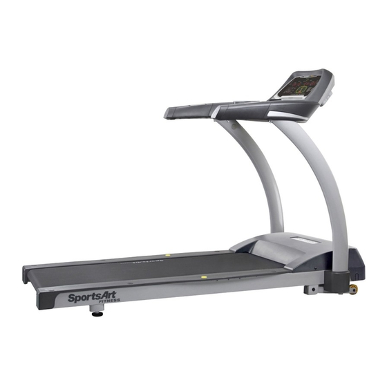
SPORTSART T611
TABLE OF CONTENTS
1. INTRODUCTION.....................................................................................................
2.
SAFETY PRECAUTIONS........................................................................................
3. LIST OF PARTS......................................................................................................
4.
ASSEMBLING THE PRODUCT...............................................................................
STEP 0 Remove Packaging Material......................................................................
STEP 1 Install the Pedestals..................................................................................
DISPLAY Overview..................................................................................................
DISPLAY Windows..................................................................................................
DISPLAY Keys.........................................................................................................
6.
OPERATION Quick Start.........................................................................................
OPERATION Workout Programs.............................................................................
User Parameter Settings....................................................................
HEART RATE Telemetry..........................................................................................
HEART RATE Contact.............................................................................................
HOW HARD SHOULD I EXERCISE?......................................................................
HOW LONG SHOULD I EXERCISE?.....................................................................
HOW OFTEN SHOULD I EXERCISE?...................................................................
MAINTENANCE Error Messages............................................................................
MAINTENANCE Fuse Replacement.......................................................................
MAINTENANCE Lubrication....................................................................................
MAINTENANCE Lubrication Prompt........................................................................
MAINTENANCE Lubrication Procedure...................................................................
MAINTENANCE Check List.....................................................................................
MAINTENACE One-Year Maintenance Log.............................................................
10.BLOCK DIAGRAM..................................................................................................
TREADMILL
..............................................................................
......................................................................................
...................................................................................
....................................................................................
..............................................................................
.....................................................................................
........................................................................
......................................................................
...............................................................................
................................................................................
1
2
3
8
10
11
13
20
23
24
25
26
27
28
30
31
32
34
34
35
35
39
41
41
43
43
43
44
45
46
46
47
50
52
53
Advertisement
Table of Contents

Subscribe to Our Youtube Channel
Related Manuals for SportsArt Fitness T611


Summary of Contents for SportsArt Fitness T611
-
Page 1: Table Of Contents
Align the Walk Belt ..................STEP 7 Adjust Walk Belt Tightness ................ STEP 8 Safety Key Cord Installation ..............5. UNDERSTANDING THE T611 DISPLAY CONSOLE DISPLAY Overview....................DISPLAY Windows....................DISPLAY Keys......................OPERATING THE T611 TREADMILL OPERATION Quick Start..................OPERATION User ID Selection ................ -
Page 2: Introduction
1. INTRODUCTION Thank you for purchasing a high quality product from SportsArt Fitness. Constructed of robust materials and built for years of trouble-free usage, the SportsArt T611 Treadmill was designed and manufactured to become an integral part of your fitness regimen. -
Page 3: Introduction Specifications
INTRODUCTION Specifications T611 Product Specifications Speed range: 0.1 to 12.0 mph; 0.2 to 20 kph Incline range: 0 to 15% Motor: 3 hp Display type: LED Running surface: 20 x 58 inches; 508 x 1473 mm Workout programs: Programmable interval, random, hill (x3), glute (30-minute and 45- minute programs), quick start, manual/track Heart rate control programs: weight loss, cardio conditioning, ZoneTrainer™... -
Page 4: Safety Precautions
2. SAFETY PRECAUTIONS IMPORTANT SAFETY PRECAUTIONS are not Such parts... - Page 5 The user weight limit for this treadmill is 180 kg (400 lb.). Note that the top speed setting of 12 mph (20 kph) is suitable for users of up to 125 kg (275 lb.). Note also that speed may automatically decrease to avoid the overload of electronic components.
- Page 6 The expense to correct such interference must be borne by the product owner or operator. WARNINGS AND CAUTIONS(FRENCH)
- Page 7 180kg (400 125kg (275 20 Amp 10 Amp ‧Ce tapis n'est pas destiné à être utilisé par des personnes (y compris des enfants) dont les capacités physiques, sensorielles ou mentales sont réduites ou qui ne disposent pas de l'expérience ou du savoir nécessaires, sauf si celles-ci ont au préalable été formées eu égard à...
- Page 8 Remarque: Ce matériel a été testé et déclaré conforme aux normes des appareils digitaux de Classe B, conformément à la partie 15 du Règlement de la FCC. Ces limites sont conçues pour offrir une protection raisonnable contre les interférences nuisibles dans une installation résidentielle. Cet appareil génère, utilise, et peut diffuser des signaux radioélectriques, et, s'il n'est pas installé...
-
Page 9: List Of Parts
3. LIST OF PARTS Assembly Parts Name Qty No. Description Hardware kit Display Cowling/handlebars Power cord Right pedestal Lube applicator tube Feeder cord Lubricant Pedestal cover Body Left pedestal Owner's manual... - Page 10 A hardware kit is provided in the packaging of this product. Please inspect the hardware kit for the following items. Parts in the Hardware Kit Name Name Specification Specification Notes Notes Screw cap (flat) Screw cap (curved) Safety key T-shaped Allen wrench T-shaped Allen wrench L-shaped Allen wrench Phillips head tool...
-
Page 11: Assembling The Product
4. ASSEMBLING THE PRODUCT -10-... -
Page 12: Step 0 Remove Packaging Material
STEP 0 Remove Packaging Material Follow steps A, B, and C to prepare the product for assembly. A. Remove the packaging material. Then cut the box flaps to lay them flat on the ground. B. Lift the rear of the treadmill to remove packaging material in the rear and center of the box. - Page 13 Make sure that walk belt is in the correct position in relation to both walk belt guides. The guides should press the sides of the walk belt downward, away from the treadmill body, as in the image marked . The image marked X shows the incorrect position; the side of the walk belt is pressed upward, toward the treadmill body.
-
Page 14: Step 1 Install The Pedestals
STEP 1 Install the Pedestals -13-... - Page 15 1-1. Remove screws (31) from the left and right pedestal bases. Remove screws (33) from the left and right pedestals (A7, A3) -14-...
- Page 16 1-2. Follow steps (a) through (d) to thread the data cable into the right pedestal (A3). (a) First, cut the zip tie that secures the data cable to the right pedestal base. Then Pull the data cable through the hole as shown. (b) Place the right pedestal (A3) flat on the ground with its bottom part facing the data cable.
- Page 17 1-3. After threading the data cable into the right pedestal, follow the steps below to secure the pedestals. (a) Insert pedestal base covers (A5) separately onto the left and right pedestals (A7, A3) (b) Insert the right pedestal (A3) onto the right pedestal base. Insert the left pedestal -16-...
- Page 18 1-4. Hand-tighten screws (31) on both left and right pedestals (A7, A3) , but do not fully secure these screws yet. -17-...
- Page 19 1-5. Follow steps (a) through (g) to assemble the cowling/handlebar assembly. (a) First, remove screws (31), (32) from the cowling/handlebar assembly (A2). (b) Set one side of the cowling/handlebar assembly onto the left pedestal (A7). (c) Connect the data cable (A3) in the right pedestal to the cable (A2) in the cowling/handlebar assembly.
- Page 20 Tuck the data cable into the pedestal. Then insert the right side of the handlebar into the right pedestal (A3). (e) Loosely secure handlebar screws (31)(32), but do not fully secure these screws. First secure pedestal base screws (see step 1-4). Then secure screws (32) in area B.
-
Page 21: Step 2 Install The Display
STEP 2 Install the Display -20-... - Page 22 Follow steps (a) through (g) to install the display. (a) First, remove display connection screws (33) from the cowling/handlebar assembly (A2). (b) To avoid damaging the display, insert the display (A1), as indicated by the arrows, onto the cowling/handlebar assembly (A2). (c) Then, tilt the display (A1) slightly.
- Page 23 (e) Connect cables in positions A and B. ( ) After connecting cables, tuck them away safely. Then slightly lift the display (A1) and press it into place. Make sure that the plastic of the display lower cover rests on the outside of the cowling/handlebar assembly plastic. (g) Use screws (33) to secure the display (A1).
-
Page 24: Step 3 Move The Treadmill
STEP 3 Move the Treadmill Please follow steps (a), (b), and (c) to put the to put the treadmill in place for use. (a) From the back of the treadmill, grip the frame with both hands. Then lift and push. (b) With the front of the treadmill slanted downward, use the front transport wheels to roll the unit. -
Page 25: Step 4 Level The Treadmill
STEP 4 Level the Treadmill 4-1. Push down on the end of the treadmill. Inspect whether levelers touch the ground evenly. 4-2. If the unit does not sit flat on the floor, follow steps (a), (b), and (c) to level the unit. (a) Rotate the leveler nut downward. -
Page 26: Step 5 Install The Power Cord
STEP 5 Install the Power Cord Please follow instructions below to install the power cord onto the treadmill. (a) First, remove screws (34) from the power cord connector. (b) Insert the end of the power cord into the connector on the product. Secure the power cord screws (34) as shown (c). -
Page 27: Step 6 Align The Walk Belt
STEP 6 Align the Walk Belt The treadmill walk belt should rotate in the center of the deck, with equal spacing on both sides. If the walk belt tends to run closer to one side , turn the rear roller screw on that side clockwise no more than 1/4 turn. -
Page 28: Step 7 Adjust Walk Belt Tightness
STEP 7 Adjust Walk Belt Tightness If the walk belt seems to pause during use the walk belt may be too loose. Stop using the treadmill and inspect walk belt tightness. At the center of the walk belt length grasp both sides of the walk belt as shown in illustration (A) and (B). -
Page 29: Step 8 Safety Key Cord Installation
STEP 8 Safety Key Cord Installation For home use, do not secure the safety key onto the product. Safety regulations require that the safety key be detachable to prevent unsupervised product use of the treadmill by children. For light commercial use, the safety key can be secured to the treadmill to prevent the key from being removed and lost. - Page 30 Secure the safety key to the treadmill as follows in steps (f)-(h) ( ) Remove one screw on the left as shown. (g) Put the safety key in its place. (h) Insert the screw back into the loop. Secure the screw back into place. Bend the loop downward 90°.
-
Page 31: Understanding The T611 Display Console Display Overview
DISPLAY Overview The T611 treadmill is designed for user convenience. With better feedback about your workout, you get better results. The following explains the display window and key functions. Please read this manual, understand the display functions, and thereby get optimum enjoyment and benefit from this product. -
Page 32: Display Windows
DISPLAY Windows CardioAdvisor™ helps you maintain a workout heart rate to meet your fitness goals. ■ 65% HR TARGET shows the optimum heart rate zone for weight loss workouts. ■ HEART RATE shows the actual heart rate. Range: 40 to 250 beats per minute ■... -
Page 33: Display Keys
DISPLAY Keys Below is a brief introduction to display keys and their functions. START – Press this key to begin exercising after inputting user information. QUICK START – Press this key to immediately begin exercising, without first inputting user information. ENTER –... - Page 34 CHANGE DISPLAY – Press this key to activate or deactivate scan mode. In scan mode, a different row of workout feedback is activated every four seconds. Top or bottom LEDs light to indicate the active row of feedback, either the top row (calories, speed, time, distance) or the bottom row (cal/hr, METs, pace, incline).
-
Page 35: Operating The T611 Treadmill Operation Quick Start
6. OPERATING THE T611 TREADMILL OPERATION Quick Start Press the QUICK START key or the SPEED ▲ key to immediately begin exercising without first inputting user information. This is called the “quick start” activation mode. The default user age is 35 years old; default user weight is 165 lb. (75 kg). -
Page 36: Operation Workout Settings
name. Then hold the ENTER key for three seconds to commit that name to the display memory. To modify a user name, while the name appears, hold the CHANGE DISPLAY key. Follow instructions above to input a new name. To delete a user's workout record, while that user ID appears, hold the CLEAR key for three seconds. - Page 37 Workout program explanations and operating instructions follow. These instructions apply to workout programs as activated via the start key. Once a workout program begins, you can select another program simply by pressing the workout program key. Your workout information, such as time and distance, will continue to accrue.
- Page 38 HILL – There are three hill programs. Press the hill key to toggle between programs 1, 2, and 3. When your preferred workout appears, press the ENTER key to confirm your choice. The following prompt appears: “TIME-1 OR DIST-2”. Press INCLINE▲/▼ keys to select time or distance, then press the ENTER key, or press numerical keys (1 or 2) to select time or distance.
- Page 39 display. You can choose either incline or speed as the variable to maintain your target heart rate. Press numeric keys to select incline (1) or speed (2). If you choose incline, the workout can begin. Press the SPEED▲ key to begin exercising.
-
Page 40: Operation User Parameter Settings
SPEED▲ key to begin exercising. Speed will gradually increase until the maximum speed or the target heart rate is reached. If no heart rate signal is detected, “NO HEART RATE READING” “PLEASE CHECK TRANSMITTER” appears on the display. COOL DOWN – When an exercise goal (time or distance) is obtained, “COOL DOWN” will appear on the message window. - Page 41 Distance represents total distance a person on the walk belt would have traveled over the treadmill's life. Press the ENTER key to proceed and view total time. (4) Upon entering the total time feedback mode, the message window will show the following: ”TIME-??????HOUR”.
-
Page 42: About Heart Rate Detection And Presentation
7. ABOUT HEART RATE DETECTION AND PRESENTATION Heart rate detection functions are optional and may not be included in your particular model. If your product is equipped with these functions, please note the following information. HEART RATE Telemetry The word "telemetry heart rate" refers to the detection of the heart rate, usually via a strap worn on the exerciser's chest and transmitted over the air for reception by a receiver built into the product. - Page 43 3. It is difficult to detect the heart rate of people with dry, course palms. Keeping palms smooth and damp improves heart rate detection. 4.The vibration of treadmills at speeds over 4 mph / 6.4 kph makes heart rate detection difficult.
-
Page 44: Guidelines For Exercise How Hard Should I Exercise
8. GUIDELINES FOR EXERCISE HOW HARD SHOULD I EXERCISE? Studies show that to achieve the benefits of aerobic exercise, it is necessary to work within your training zone. Your training zone depends on your age and level of fitness. The above chart indicates the recommended Heart Rate training zones (darkened area of the chart). -
Page 45: Maintenance
9. MAINTENANCE MAINTENANCE Error Messages The following messages can appear on this product for diagnostic purposes. ERR1 – Optic sensor error. The main program IC has not received the optic sensor signal. Re-start the unit to see if normal operation will resume. ERR3 –... -
Page 46: Maintenance Fuse Replacement
MAINTENANCE Fuse Replacement When current is excessive, the fuse breaks to protect other components. Follow steps (a) through (g) to replace the fuse. (a) Press the fuse holder cap. (b) Turn it counterclockwise. (c) The fuse and fuse holder cap will spring out. (d) Remove the bad fuse from the fuse holder cap. -
Page 47: Maintenance Lubrication
MAINTENANCE Lubrication Periodic maintenance is crucial to the performance of fitness equipment, just like it is to the performance of an automobile. The better you maintain a product, the longer it will serve your needs. This treadmill requires periodic lubrication of the walk belt and has a built-in system to prevent overuse without maintenance. -
Page 48: Maintenance Lubrication Procedure
MAINTENANCE Lubrication Procedure Remove the left end cap and landing strip. Remove screws from the finger guard on the left side. Then remove the finger guard. Simultaneously press and hold INCLINE▲ + INCLINE▼ + 0 keys for two seconds. The treadmill will enter lubrication mode. It will operate at low speed and no▲ or▼ keys will operate. - Page 49 Insert the applicator tube so the line on the applicator touches the side of the walk belt. Apply 50 cc from the bottle of liquid lubricant. Let the treadmill operate two to three minutes so the lubricant can disperse. 7. Remove the applicator and the bottle of lubricant. -48-...
- Page 50 Once the lubrication mode is activated, the message “PLEASE PRESS THE STOP KEY AFTER FINISHING LUBRICATION” will appear on the screen. At this point, press the STOP key to deactivate the lubrication mode. This clears the lubrication distance value. A new lubrication distance value will begin to accrue. After the lubrication process has been completed, secure the finger guard back into place.
-
Page 51: Maintenance Check List
MAINTENANCE Check List Like cars, fitness products require maintenance. Regular maintenance extends the life of your fitness product, and failure to provide regular maintenance will void your warranty. Copy the maintenance log sheet and record maintenance work. Daily tasks 1. Check the product, including the safety key, for safe operation. Secure any loose screws. - Page 52 4. Clean and lubricate walk deck bushings. For lubrication of deck bushings, use red lithium grease. Remove bushing lubricant that touches the walk belt or deck surface. General Notes on Maintenance Note that product maintenance requirements depend on usage and environment. This schedule is based on average use.
-
Page 53: Maintenace One-Year Maintenance Log
MAINTENACE One-Year Maintenance Log Facility Name: Maintenance Supervisor: Product serial number: Product Model Number: Start Date: End Date: Daily Tasks Week1 Week2 Week3 Week4 1.Safe 2.Clean Daily Tasks Week5 Week6 Week7 Week8 1.Safe 2.Clean Daily Tasks Week9 Week10 Week11 Week12 1.Safe 2.Clean Monthly Tasks... -
Page 54: Block Diagram
10. BLOCK DIAGRAM T611 Your Authorized Distributor -53-...
Need help?
Do you have a question about the T611 and is the answer not in the manual?
Questions and answers