Advertisement
Quick Links
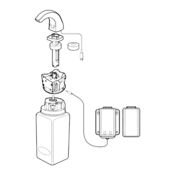
Installation Instructions for the Electronic SURETOUCH* Foam Soap System
IMPORTANT! For secure mounting, follow instructions thoroughly.
A
B
C
E
A
B
C
D
E
F
F
G
H
G
Soap Discharge Head
Support Shaft
Support Ring
Battery Compartment Cover
Motor Module
Split Support Ring
(Optional)
Soap Refi ll Bottle
Battery Compartment Base
H
D
Form 033955 • 6/2013
Advertisement

Subscribe to Our Youtube Channel
Related Manuals for Kimberly-Clark Suretouch


Summary of Contents for Kimberly-Clark Suretouch
- Page 1 Installation Instructions for the Electronic SURETOUCH* Foam Soap System stallation Instructions for the Electronic SURETOUCH* Foam Soap System IMPORTANT! For secure mounting, follow instructions thoroughly. MPORTANT! For secure mounting, follow instructions thoroughly. Soap Discharge Head Support Shaft Support Ring Battery Compartment Cover...
- Page 2 7. Rotate the support shaft so the arrow Dispenser Installation 11. IMPORTANT – Using a Phillips bit in a points toward the sink (see figure 6). power driver, tighten at full speed the 2 screws on the support shaft until the 8.
- Page 3 12. Use the hand tool provided to complete the tightening of the support shaft. Tighten in a clockwise direction (see figure 11). 13. Push the signal cable attached to the soap discharge head thru the opening in the support shaft (see figure 12). 14.
- Page 4 22. Push the battery compartment cover onto the 24. Install the power cable plug into the Soap Refill Bottle Installation and Removal battery compartment base until both the top power receptacle on the motor module and bottom of the cover snap into place (see (see figure 23).
- Page 5 Dispenser Deactivation Instructions User Guide for the Electronic SURETOUCH* Foam Soap System LED INDICATORS: There are several indicator LED’s on the soap IMPORTANTE IMPORTANT discharge head which are used as follows: Instrucciones para desactivar Instructions de désactivation IMPORTANT temporalmente las distribuidoras temporaire du distributeur (modèle...
- Page 6 Troubleshooting Guide Troubleshooting Guide (continued) Problem Cause Correction Problem Cause Correction Support shaft does not Hole in countertop too small. Drill out hole to 1" minimum Soap does not Batteries can no longer Replace batteries. fit into countertop. diameter. dispense when activate the dispenser activated.
- Page 7 KIMBERLY-CLARK CORPORATION AANVAARDT GEEN AANSPRAKELIJKHEID VOOR LICHAMELIJK LETSEL OF MATERIËLE SCHADE DIE VOORTVLOEIT UIT EEN NIET DOOR KIMBERLY-CLARK UITGEVOERDE INSTALLATIE. KIMBERLY-CLARK CORPORATION ESCLUDE LA PROPRIA RESPONSABILITÀ PER DANNI ALLA PERSONA O A PROPRIETÀ DERIVANTI DA OPERAZIONI DI INSTALLAZIONE NON EFFETTUATE DA KIMBERLY-CLARK.
- Page 8 Installation Instructions for the Electronic SURETOUCH* Foam Soap System stallation Instructions for the Electronic SURETOUCH* Foam Soap System MPORTANT! For secure mounting, follow instructions thoroughly. IMPORTANT! For secure mounting, follow instructions thoroughly. Soap Discharge Head Support Shaft Support Ring Battery Compartment...
-
Page 9: Dispenser Installation
Dispenser Installation Materials Required: • Power Driver • 1” Diameter Hole • Clear Silicone Caulk • Phillips Bit Saw (Diamond Bit • Safety Glasses • Phillips Screwdriver for Granite or Stone) • Magic Marker • Cutting Fluid Note: If drilling of the countertop is required, be sure to use an approved KC Installer or other trained professional. - Page 10 7. Rotate the support shaft so the arrow 11. IMPORTANT – Using a Phillips bit in a points toward the sink (see figure 6). power driver, tighten at full speed the 2 screws on the support shaft until the 8. Remove the adhesive liner from the plastic heads break away.
- Page 11 12. Use the hand tool provided to complete the tightening of the support shaft. Tighten in a clockwise direction (see figure 11). 13. Push the signal cable attached to the soap discharge head thru the opening in the support shaft (see figure 12). 14.
- Page 12 Fig. 18 Fig. 17 18. Position the clear tube on the signal cable into the notch on the bottom of the support shaft (see figure 17). 19. Remove the protective cap on the signal cable plug. Align the yellow arrow on the signal cable plug with the yellow arrow on the motor module receptacle (see figure 18).
- Page 13 22. Pull the battery insulator strip out from Note: The red and yellow lights on the the back of the battery compartment bottom of the soap discharge head should (see figure 21). begin to blink, indicating proper installation. If the lights do not flash, refer to the 23.
- Page 14 Soap Refill Bottle Installation and Removal 1. Slip the straw into the underside of the motor module (see figure 26). 2. Push the refill bottle flush to the motor module until both snaps are secure (see figure 27). Note: The red and yellow lights on the bottom of the soap discharge head should stop blinking, indicating proper installation.
- Page 15 Dispenser Deactivation Instructions IMPORTANTE Instrucciones p IMPORTANT temporalmente Instructions to temporarily deactivate 11331 & 34829 11331 & 34829 p dispensers to permit sink/dispenser cleaning. lavabos y distrib 1. Ponga la man 5 sec. distribuidora. 2. Sostenga la m la distribuidora el jabón se dosi 3.
-
Page 16: Led Indicators
User Guide for the Electronic SURETOUCH* Foam Soap System LED InDIcatoRS: There are several indicator LED’s on the soap discharge head which are used as follows: Yellow LED (Low Product) – The yellow LED will begin to flash slowly (1 time every second) when the soap refill has between 50 and 90 shots of soap remaining. -
Page 17: Troubleshooting Guide
troubleshooting guide Problem Cause Correction Support shaft does not Hole in countertop too small. Drill out hole to 1" minimum fit into countertop. diameter. Support shaft still loose Plastic screw head broke Use tool provided to manually after tightening. prematurely. tighten the support fasteners. - Page 18 troubleshooting guide (continued) Problem Cause Correction Soap does not Batteries can no longer Replace batteries. dispense when activate the dispenser activated. (continued) (Red LED flashing 4 times per second). Signal cable from discharge Replace discharge head. head damaged. Water contamination on Replace motor module.
- Page 19 KIMBERLY-CLARK CORPORATION AANVAARDT GEEN AANSPRAKELIJKHEID VOOR LICHAMELIJK LETSEL OF MATERIËLE SCHADE DIE VOORTVLOEIT UIT EEN NIET DOOR KIMBERLY-CLARK UITGEVOERDE INSTALLATIE. KIMBERLY-CLARK CORPORATION ESCLUDE LA PROPRIA RESPONSABILITÀ PER DANNI ALLA PERSONA O A PROPRIETÀ DERIVANTI DA OPERAZIONI DI INSTALLAZIONE NON EFFETTUATE DA KIMBERLY-CLARK.
Need help?
Do you have a question about the Suretouch and is the answer not in the manual?
Questions and answers