
Related Manuals for Thermal Arc 160 TS ARCMASTER


Summary of Contents for Thermal Arc 160 TS ARCMASTER
-
Page 1: Service Manual
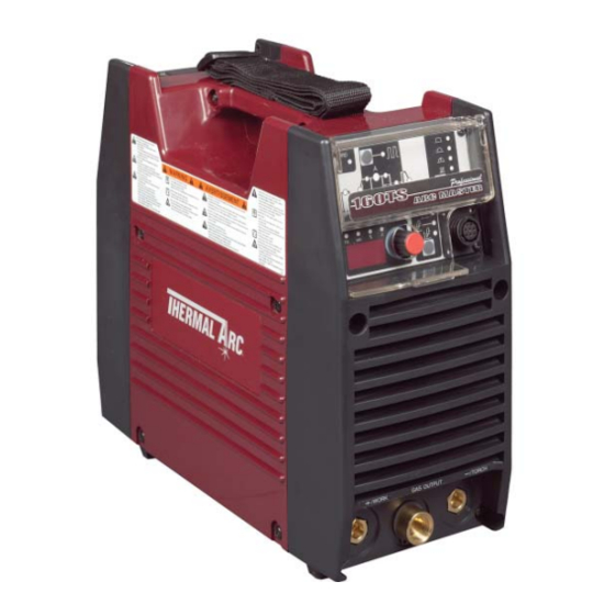
160 TS ® ARCMASTER INVERTER ARC WELDER Service Manual Revision: AB Issue Date: June 16, 2006 Manual No: 0-4881B Operating Features: INVERTER DC CC PHASE GTAW SMAW... - Page 2 800-752-7621, or visit us on the web at www.thermalarc.com. This Operating Manual has been designed to instruct you on the correct use and operation of your Thermal Arc ® product. Your satisfaction with this product and its safe operation is our ultimate concern. Therefore, please take the time to read the entire manual, especially the Safety Precautions.
- Page 3 WARNINGS Read and understand this entire Manual and your employer’s safety practices before installing, operating, or servicing the equipment. While the information contained in this Manual represents the Manufacturer’s best judgment, the Manufacturer assumes no liability for its use. Service Manual Number 0-4881B for: ArcMaster 160 TS Inverter Welding Power Supply Part No.
-
Page 4: Table Of Contents
CONTENTS SECTION 1: SAFETY INSTRUCTIONS AND WARNINGS....................3 1.01 Arc Welding Hazards ............................3 1.02 PRINCIPAL SAFETY STANDARDS ........................7 1.03 PRECAUTIONS DE SECURITE EN SOUNDAGE A L’ARC..................8 1.04 Dangers relatifs au soudage à l’arc ........................8 1.05 PRINCIPAL SAFETY STANDARDS ........................12 SECTION 2: INTRODUCTION ............................13 2.01 How To Use This Manual............................13 2.02 Equipment Identification.............................13 2.04 Symbol Chart..............................14... - Page 5 CONTENTS SECTION 11: ADVANCED TROUBLE SHOOTING....................52 11.01 System-Level Fault Isolation ..........................52 1. Opening the Enclosure ............................53 11.02 Verification and Remedy to the Indicated Error Codes ..................56 1. E01 “Over-Temperature at the primary side”...................... 57 2. E02 “Over-Temperature at the secondary side”....................57 3.
-
Page 7: Section 1: Safety Instructions And Warnings
ARCMASTER 160TS SECTION 1: SAFETY INSTRUCTIONS AND WARNINGS WARNING PROTECT YOURSELF AND OTHERS FROM POSSIBLE SERIOUS INJURY OR DEATH. KEEP CHILDREN AWAY. PACEMAKER WEARERS KEEP AWAY UNTIL CONSULTING YOUR DOCTOR. DO NOT LOSE THESE INSTRUCTIONS. READ OPERATING / INSTRUCTION MANUAL BEFORE INSTALLING, OPERATING OR SERVICING THIS EQUIPMENT. Welding products and welding processes can cause serious injury or death, or damage to other equipment or property, if the operator does not strictly observe all safety rules and take precautionary actions. - Page 8 ARCMASTER 160TS 14. Wear a safety harness to prevent falling if working above fool level. WARNING 15. Keep all panels and covers securely in place. FUMES AND GASES can be hazardous your health. Welding produces fumes and gases. Breathing these fumes and gases can be hazardous to your health.
- Page 9 ARCMASTER 160TS 6. Do not weld in locations near degreasing, cleaning, or spraying operations. The heat and rays of the arc can WARNING react with vapors to from highly toxic and irritating gases. FLYING SPARKS AND HOT METAL can cause injury. Chipping and grinding cause flying metal.
- Page 10 ARCMASTER 160TS 6. Reinstall panels or guards and close doors when servicing is finished and before starting engine. WARNING Engines can be dangerous. WARNING SPARKS can cause BATTERY GASES TO EXPLODE; BATTERY ACID can burn eyes and skin. WARNING Batteries contain acid and generate explosive gases. 1.
-
Page 11: Principal Safety Standards
ARCMASTER 160TS 1.02 PRINCIPAL SAFETY STANDARDS WARNING This product, when used for welding or cutting, Safety in Welding and Cutting, ANSI Standard Z49.1, from produces fumes or gases which contain chemicals the American Welding Society, 550 N.W. LeJeune Rd., know to the State of California to cause birth defects Miami, FL 33126. -
Page 12: Precautions De Securite En Soundage A L'arc
ARCMASTER 160TS 1.03 PRECAUTIONS DE SECURITE EN SOUNDAGE A L’ARC MISE EN GARD LE SOUDAGE A L’ARC EST DANGEREUX PROTEGEZ-VOUS, AINSI QUE LES AUTRES, CONTRE LES BLESSURES GRAVES POSSIBLES OU LA MORT. NE LAISSEZ PAS LES ENFANTS S’APPROCHER, NI LES PORTEURS DE STIMULATEUR CARDIAQUE (A MOINS QU’ILS N’AIENT CONSULTE UN MEDECIN). - Page 13 ARCMASTER 160TS muni d’un réducteur de tension. Utilisez plutôt une yeux lorsque vous soudez ou que vous observez source de courant continu. l’exécution d’une soudure. 14. Portez un harnais de sécurité si vous travaillez en 2. Portez des lunettes de sécurité approuvées. Des hauteur.
- Page 14 ARCMASTER 160TS 4. Lisez les fiches signalétiques et les consignes du fabricant relatives aux métaux, aux produits 6. N’oubliez pas qu’une soudure réalisée sur un plafond, consummables, aux revêtements et aux produits un plancher, une cloison ou une paroi peut enflammer l’autre côté.
- Page 15 ARCMASTER 160TS 3. Eloignez les bouteilles de tout circuit électrique ou de tout soudage. 5. Faites attention de ne pas renverser de carburant. Nettoyez tout carburant renversé avant de faire démarrer le moteur. 4. Empêchez tout contact entre une bouteille et une électrode de soudage.
-
Page 16: Principal Safety Standards
ARCMASTER 160TS 4. N’utilisez pas une source de courant de soudage pour 1.05 PRINCIPAL SAFETY STANDARDS charger accumulateur survolter momentanément un véhicule. Safety in Welding and Cutting, ANSI Standard Z49.1, from the American Welding Society, 550 N.W. LeJeune Rd., Miami, FL 33126. -
Page 17: Section 2: Introduction
Include the Service Manual number and equipment identification numbers. Electronic copies of this manual can also be downloaded at no charge in Acrobat PDF format by going to the Thermal Arc web site listed below and clicking on the Literature Library link: http://www.thermalarc.com... -
Page 18: Symbol Chart
ARCMASTER 160TS 2.04 Symbol Chart Note that only some of these symbols will appear on your model. STICK (Shielded Metal Arc SMAW) Pulse Current Function Hertz (frequency) Spot Time (GTAW) Remote Control (Panel/Remote) Remote Function DC (Direct Current) Arc Control (SMAW) AC (Alternating Current Gas Post-Flow Standard Function... -
Page 19: Description
ARCMASTER 160TS 2.05 Description The Thermal Arc™ Model 160TS is a self contained single-phase DC arc welding power sources with Constant Current (CC) output characteristics. This unit is equipped with a Digital Volt/Amperage Meter, gas control valve, built in Sloper and Pulser, lift arc starter, and high-frequency arc starter for use with Gas Tungsten Arc Welding (GTAW), Gas Tungsten Arc Welding-Pulsed (GTAW-P) Gas Tungsten Arc Welding- Sloped (GTAW-S), and Shielded Metal Arc Welding (SMAW) processes. -
Page 20: Functional Block Diagrams
ARCMASTER 160TS 2.06 Functional Block Diagrams Figure 2-2 illustrates the functional block diagram of the 160TS-power supply. Input Hall Current Main Input IGBT Main Output Capacitor Circuit Diode Inverter Transformers Diodes Transformer Power Switch Filter DC Power Themal (T1) (HCT1) Detector Primary Voltage... -
Page 21: Section 3: Installation
3.01 Environment The ARC MASTER 160TS is designed for use in adverse environments. WARNING Examples of environments with increased Thermal Arc advises that this equipment be adverse conditions are: electrically connected qualified electrician. a. In locations in which freedom of movement... -
Page 22: Electrical Input Requirement
ARCMASTER 160TS for single phase electrical input power. For direct 3.04 Electrical Input Requirement wiring installation have a qualified person install according to all applicable codes and instructions Operate the welding power source from a single- single and three phase electrical input power phase 50/60 Hz, AC power supply. -
Page 23: Input Power
The ARC MASTER 160TS is designed for use with a generator as an input power source. Contact an accredited Thermal Arc service agent for the proper sizing and set-up recommendations of a generator power source system. As a general rule, depending on the type of generator used, the generator capacity should be twice the maximum rating of the welder. -
Page 24: High Frequency Interference
ARCMASTER 160TS 3.07 High Frequency Interference 3.08 Duty Cycle Interference may be transmitted by a high The duty cycle of a welding power source is the frequency initiated or stabilized arc welding percentage of a ten (10) minute period that it can machine in the following ways: be operated at a given output without causing 1. -
Page 25: Specifications
230V Thermal Arc continuously strives to produce the best product possible and therefore reserves the right to change, improve or revise the specifications or design of this or any product without prior notice. Such updates or changes do not entitle the buyer of equipment previously sold or shipped to the corresponding changes, updates, improvements or replacement of such items. -
Page 27: Section 4: Operator Controls
ARCMASTER 160TS SECTION 4: OPERATOR CONTROLS 4.01 ARC MASTER 160TS Controls Figure 4-1: ARC MASTER 160TS Power Source Socket Pin Function 1. Control Knob: This control sets the selected Earth (Ground) weld parameter, rotating it clockwise Torch Switch Input (24V) to increases the parameter that is indicated on (connect pins 2 &... - Page 28 ARCMASTER 160TS 3. Positive Terminal: Welding current flows from the Power Source via heavy duty Dinse type terminal (Size 25mm Dinse). It is essential, however, that the male plug is inserted and turned securely to achieve a sound electrical connection. 4.
-
Page 29: Weld Process Selection For 160Ts
ARCMASTER 160TS 4.02 Weld Process selection for 160TS Weld Mode Weld Process LIFT Selection STICK Description 2T operation in TIG Modes using remote devices to control contactor & current 4T operation in TIG Modes with crater fill using a remote contactor device to control SLOPE sequence. -
Page 30: Weld Parameter Descriptions For Arc Master 160Ts
ARCMASTER 160TS 4.03 Weld Parameter Descriptions for ARC MASTER 160TS Figure 4-3: ARC MASTER 160TS Front Panel with Parameter Description Parameter Description This parameter operates in TIG modes only and is used to provide gas to the weld zone prior to striking the arc, once the torch trigger switch has been pressed. - Page 31 ARCMASTER 160TS Parameter Description DOWN SLOPE This parameter operates in TIG modes only and is used to set the time for the weld current to ramp down, after the torch trigger switch has been CRATER CUR. pressed, to This control is used to eliminate the crater that can form at the completion of a weld.
- Page 32 ARCMASTER 160TS Figure 4-4: ARC MASTER 160TS Front Panel with Parameter Description This parameter operates in STICK weld mode and is used to improve the HOT START start characteristics for stick electrodes. e.g. low hydrogen electrodes. It (WELD) sets the peak start current on top of the current.
-
Page 33: Weld Parameters For Arc Master 160Ts
ARCMASTER 160TS 4.04 Weld Parameters for ARC MASTER 160TS Weld Mode Weld Parameter Factory Incremental LIFT Parameter Range Setting Unit STICK PRE-FLOW 0.0 to 1.0 sec 0 sec 0.1 sec HOT START 0 to 70A INITIAL CUR. 1 to 160A UP SLOPE 0 to 15 sec 1 sec... -
Page 34: Power Source Features
ARCMASTER 160TS 4.05 Power Source Features Feature Description • Almost all welding parameters are adjustable New Digital Control • Touch switches eliminate mechanical damage Touch Panel Switches • Protects front panel controls Front Control Cover • Displays selected weld parameter value Digital Meter •... -
Page 35: Section 5: Set-Up For Smaw (Stick) And Gtaw (Tig)
ARCMASTER 160TS SECTION 5: SET-UP FOR SMAW (STICK) AND GTAW (TIG) Conventional operating procedures apply when using the Welding Power Source, i.e. connect work lead directly to work piece and electrode lead is used to hold electrode. Wide safety margins provided by the coil design ensure that the Welding Power Source will withstand short- term overload without adverse effects. -
Page 36: Section 6: Sequence Of Operation
ARCMASTER 160TS SECTION 6: SEQUENCE OF OPERATION Note Scroll Buttons are used to select the parameters to be set. The LED’s show which function is being adjusted on the weld sequence graph. Refer to the Symbols Table located in the front of the manual for Symbol descriptions. -
Page 37: Stick Welding
ARCMASTER 160TS Use the Scroll Buttons to move to the parameter to be set. The LED will show which function is 6.01 Stick Welding being adjusted on the weld sequence graph. Use Connect work lead to negative terminal the control knob to adjust each parameter. Connect electrode lead to positive terminal Switch machine on PRE-FLOW... -
Page 38: Slope Mode Sequence
ARCMASTER 160TS 6.03 Slope Mode Sequence Switch Switch Switch Switch Closed Closed Open Open Weld Current Down Slope Slope Initial Final Current Current Preflow Postflow Figure 6-3: Slope Mode Sequence 1. To start the Slope sequence, close the remote 2. Open Remote Switch – current increases to switch contacts. -
Page 39: Pulse Controls
ARCMASTER 160TS 6.05 Pulse Controls (Pulse Width) (Pulse Frequency) (Peak Current) (Base) Background Current The Pulse controls are used primarily to control heat input. Pulse offers a number of advantages as follows: 1) Control puddle – size and fluidity (especially out of position). 2) Increase penetration 3) Travel speed control 4) Better consistent quality... -
Page 40: Section 7: Routine Maintenance
ARCMASTER 160TS SECTION 7: ROUTINE MAINTENANCE The only routine maintenance required for the power supply is a thorough cleaning and inspection, with the frequency depending on the usage and the operating environment. WARNING Disconnect primary power at the source before opening the enclosure. Wait at least two minutes before opening the enclosure to allow the primary capacitors to discharge. - Page 41 6 Months Bring the unit to an authorized Thermal Arc Service Center to remove any accumulated dirt and dust from the interior. This may need to be done more frequently under exceptionally dirty conditions.
-
Page 42: Section 8: Basic Troubleshooting
WARNING There are extremely dangerous voltages and power levels present inside this product. Do not attempt to open or repair unless you are an Accredited Thermal Arc Service Agent and you have had training in power measurements and troubleshooting techniques. - Page 43 ARCMASTER 160TS Description Possible Cause Remedy 5 Uneven leg length Wrong placement of filler rod. Re-position filler rod. in fillet joint. 6 Electrode melts A Electrode is connected to the A Connect the electrode to the when arc is struck. ‘+’...
- Page 44 ARCMASTER 160TS Description Possible Cause Remedy 11 Welding arc can A Work clamp is not connected A Connect the work clamp to not be established. to the work piece or the the work piece or connect the work/torch leads are not work/torch leads to the right connected to the right welding welding terminals.
-
Page 45: Stick Welding Problems
ARCMASTER 160TS 8.02 Stick Welding Problems Description Possible Cause Remedy 1 Gas pockets or Electrodes are damp. Dry electrodes before use. voids in weld Welding current is too high. Reduce welding current. metal (Porosity). Surface impurities such as Clean joint before welding. oil, grease, paint, etc. - Page 46 ARCMASTER 160TS 4 Portions of the weld Small electrodes used on Use larger electrodes and pre- run do not fuse to heavy cold plate. heat the plate. the surface of the Welding current is too low. Increase welding current. metal or edge of the joint.
- Page 47 ARCMASTER 160TS 5 Non-metallic parti- A Non-metallic particles may be A If bad undercut is present, cles are trapped in trapped in undercut from clean slag out and cover with a the weld metal (slag previous run. run from a smaller diameter inclusion).
-
Page 48: Power Source Problems
ARCMASTER 160TS 8.03 Power Source Problems Description Possible Cause Remedy 1 The welding arc The Primary supply voltage Switch ON the Primary cannot be has not been switched ON. supply voltage. established. The Welding Power Source Switch ON the Welding switch is switched OFF. - Page 49 ARCMASTER 160TS Description Possible Cause Remedy SLOPE 5 Gas flow won’t shut A Weld Mode ( A Strike an arc to complete the REPEAT SPOT off. ) was weld cycle. POST-FLOW changed before gas time had finished. Switch machine off then on to reset solenoid valve sequence.
-
Page 50: Section 9: Voltage Reduction Device (Vrd)
In addition to the above tests and specifically in relation to the VRD fitted to this machine, the following periodic tests should also be conducted by an accredited Thermal Arc service agent. Description... -
Page 51: Switching Vrd On/Off
ARCMASTER 160TS 2) Verify the no-load voltage (OCV) using a DC voltmeter. (The capability of the voltmeter should be more than 100VDC.) 3) The normal no-load voltage is approximately 18V. 4) In STICK welding mode, mark and then turn potentiometer VR1 on PCB4 (WK-5449) fully clockwise and turn off the VRD. - Page 52 ARCMASTER 160TS B) Remove four mounting screws from the control panel (see Figure 9-2). Figure 9-2: VRD ON/OFF Step B,C C) Access the VRD control by gently prying back the front panel controls to reveal the VRD on/off potentiometer (see Figure 9-3). CAUTION Do not pull back the front panel with excessive force as this will unplug control PCB.
- Page 53 ARCMASTER 160TS D) Turning the VRD ON/OFF (see Figure 9-3). To turn VRD ON: rotate the trim potentiometer (VR1) on the display PCB fully clockwise. When VRD is turned ON check that it operates as per VRD Specifications on page 9.01. To turn VRD OFF: rotate the trim potentiometer (VR1) on the display PCB fully counter clockwise.
-
Page 54: Section 10: Power Source Error Code
TH1 (protects B Fan ceases to Have an Accredited Fan operates at max IGBTs) is greater operate. Thermal Arc Service speed. than 80ºC for about Agent investigate. C Air flow is restricted E01 resets when TH1 1 second. by vents being decreases to 70ºC... - Page 55 Possible Cause Remedy Remarks 4 E94 error code The Welding Power Have an Accredited Weld current ceases. displayed Source’s Thermal Arc Service Buzzer sounds Temperature sensor temperature sensors Agent check or constantly. TH1 for IGBTs or have malfunctioned. replace the Switch machine off.
-
Page 56: Section 11: Advanced Trouble Shooting
This section provides the information replaced with a new one. The faulty subassembly needed to take live measurements on the various should then be returned to Thermal Arc through subsystems within the power supply, and established procedures. replace those subsystems that prove faulty. -
Page 57: Opening The Enclosure
ARCMASTER 160TS 1. Opening the Enclosure a) Verify that the switch on the power supply and the switch on the switchboard (distribution panel) are all OFF. Figure 11-1 Switch OFF CAUTION The capacitors inside the power supply will slowly discharged after you turn off the switch of the power supply or the switch at the breaker box (distribution panel). - Page 58 ARCMASTER 160TS c) Loosen the screws on the Front Panel and the Rear Panel by turning them approximately two turns CCW. Figure 11-3 Loosen screws Note DO NOT remove the screws completely. d) Pull the front panel slightly forward and pull the rear panel slightly backward. The interlocking hooks of the side case covers can now be disengaged from the Front Panel and Rear Panel Figure 11-4 Loosen Front Panel and Rear Panel...
- Page 59 ARCMASTER 160TS e) Remove the Side Panel. Figure 11-5 Remove Side Panel f) Remove PCB Cover sheet by removing the four clips. Figure 11-6 Remove PCB Cover Note When you re-assemble the parts, conduct the above process backwards.
-
Page 60: Verification And Remedy To The Indicated Error Codes
ARCMASTER 160TS 11.02 Verification and Remedy to the Indicated Error Codes Note The capacitors inside the power supply will slowly discharged after you turn off the switch of the power supply or the switch at the breaker box (distribution panel). Wait at least 5 minutes for the discharge to complete and then remove the cases to continue your inspection and repair (or maintenance) inside the power supply. -
Page 61: E01 "Over-Temperature At The Primary Side
ARCMASTER 160TS 1. E01 “Over-Temperature at the primary side” 2. E02 “Over-Temperature at the secondary side” Cause: Occurs when an over-temperature condition Cause: of the primary IGBT is detected. Occurs when an over-temperature condition of the secondary IGBT and diode are detected. Verification/Remedy: a) Unit may be in thermal shutdown mode. -
Page 62: E03 "Primary Over-Current Failure
ARCMASTER 160TS 3. E03 “Primary Over-Current Failure” Verification/Remedy: Cause: a) Verify a secure connection of the harness Occurs when excessive current is detected wired between CN5-6 on PCB1 (WK-5466) flowing into the primary side of the main and Thermistors (TH1, TH2). transformer. -
Page 63: Verification And Remedy To Failures Without Indication Codes
ARCMASTER 160TS 11.03 Verification and Remedy to Failures without Indication Codes Refer to Note on Section 11.02. 1. “Cooling Fan (FAN1) Failure” (Fan is not 2. “Gas Valve Failure” (No Gas flow through rotating.) unit) Cause: Cause: Occurs when the cooling fan (FAN1) is Occurs when the gas valve (SOL1) is defective, damaged or the driving voltage is defective, damaged or the driving voltage is... -
Page 64: No Weld Output
ARCMASTER 160TS e) Replace PCB4 (WK-5449) and PCB5 (WK- Verify a secure connection of the welding cable, 5448). stick rod holders, ground clamp and dinse connectors and there are no open circuits. Refer to section 12.03.4, 12.03.5 for the replacement of PCB4 and PCB5. c) Verify the no-load voltage (OCV). -
Page 65: Operating Panel Failure" (Led's Do Not Light Properly Or Welding Setting Cannot Be Established.)
ARCMASTER 160TS 4. “Operating Panel Failure” (LED’s do not 5. “High Frequency Output Failure” (Unit does light properly or welding setting cannot be not generate High Frequency.) established.) Cause: Occurs when the High Frequency unit Cause: (HF UNIT1) is defective or blown. Occurs when there is a connection failure among PCB1 (WK-5466), PCB5 (WK-5448), PCB6 (WK-5449) and PCB1 or PCB5 or PCB6... -
Page 66: Fault Isolation Tests
ARCMASTER 160TS 11.04 Fault Isolation Tests Verify there are no short circuits, burnt or R6 on 1. Preparation broken wires between the HF UNIT1 and WK5609 PCB3. Its resistance can be The following initial conditions must be met measured across pins 1 and 3 of CN3 prior to starting any of the procedures in this (PCB3) WK5609. -
Page 67: Verification Of The Power Input Circuitry
ARCMASTER 160TS 11.05 Verification of the Power Input Circuitry CAUTION Before performing any portion of the procedure below, make certain the unit is placed in the initial set up condition as described in section 11.04.1 "Preparation" 1. Verification of the AC input voltage using an AC voltmeter. a) Verify input voltage (Phase-to Phase) using an AC voltmeter. - Page 68 ARCMASTER 160TS measured in #1 above. Replace diode D1 if the calculated measurement is not within the corresponding range (260 ~ 360VDC) following the process in section 12.03.1. Figure 11-8: The check points “+“ and “-“ f) Verify bus voltage (the voltage of the electrolytic capacitor after rectification) using a DC voltmeter.
-
Page 69: Verification Of The Power Supply Voltage
ARCMASTER 160TS 2. Verification of the Power Supply Voltage CAUTION Before performing any portion of the procedure below, make certain the unit is placed in the initial set up condition as described in section 11.04.1 "Preparation" . a) Verify Power Supply voltage using an DC voltmeter. (The capability of the voltmeter should be more than 50VDC.) Operate at all input voltages as noted on the nameplate on the rear panel when testing the power supply. - Page 70 ARCMASTER 160TS Figure 11-11: Checkpoints CN2 on PCB1 Check Point Reference ACCEPTABLE PCB1 PCB1 VALUE Pin 1 on CN2 Pin 2 on CN2 +24VDC Table 11-2: Checkpoints CN2 on PCB1 c) If any of these voltages are not present or are below a 10% tolerance, replace the PCB1 (WK- 5466).
-
Page 71: Verification Of The Cooling Fan, Fan1, Drive Circuitry
ARCMASTER 160TS 3. Verification of the Cooling Fan, FAN1, Drive Circuitry CAUTION Before performing any portion of the procedure below, make certain the unit is placed in the initial set up condition as described in section 11.04.1 "Preparation" . a) Verify the condition of the cooling fan, FAN1, using a DC voltmeter. (The capability of the voltmeter should be more than 50VDC.) Using a DC voltmeter, measure between PIN 1 (Positive [+]) and PIN 2 (Negative [-]) of CN11 on PCB1 (WK-5466). -
Page 72: Verification Of The Gas Valve, Sol1, Drive Circuitry
ARCMASTER 160TS At the time of a low output and standby, fan rotation becomes slow. Therefore, exact voltage measuring becomes impossible. When verifying the voltage, Verify that the AC input voltage remain within the operating range of the unit. (The AC input does not drop below 180VAC). 4. -
Page 73: Verification Of The Primary Diode (D1)
ARCMASTER 160TS c) When verifying the voltage, Verify that the AC input voltage remain within the operating range of the unit. (The AC input does not drop below 180VAC). 5. Verification of the primary Diode (D1) CAUTION Before performing any portion of the procedure below, make certain the unit is placed in the initial set up condition as described in section 11.4.1 "Preparation". -
Page 74: Verification Of The Secondary Diode (D2, D3)
ARCMASTER 160TS 6. Verification of the secondary Diode (D2, D3) CAUTION Before performing any portion of the procedure below, make certain the unit is placed in the initial set up condition as described in section 11.04.1 "Preparation" . a) Verify the characteristic of the secondary diode, D2 and D3, using a diode tester. b) Refer to Table 11-6 and Figure 11-15 for the checkpoints on D2 and D3. -
Page 75: Verification Of The Primary Igbt (Q1A-Q4C)
ARCMASTER 160TS 7. Verification of the primary IGBT (Q1A-Q4C) CAUTION Before performing any portion of the procedure below, make certain the unit is placed in the initial set up condition as described insection 11.04.1 "Preparation". a) Check whether there are any abnormalities on the appearance of PCB6 and PCB7. b) Verify the characteristic of the primary IGBT (Q1A-Q4C), using a diode tester. -
Page 76: Verification Of No-Load Voltage (Ocv)
ARCMASTER 160TS 8. Verification of No-load Voltage (OCV) 1) When in HF TIG mode, the unit will generate high voltage. To prevent personal harm and test equipment CAUTION damage, mark and then remove the Before performing any portion of the indicated wire from the HF UNIT1 shown procedure below, make certain the unit is in Figure 11-17. -
Page 77: Output Load Test
ARCMASTER 160TS g) Slowly turn the Control Knob clockwise 9. Output Load Test This test verifies that the output current, to the maximum of the power supply, (amperage) controls are functioning then counter clockwise, back to 1 Amps properly. A clamp-type amperage meter or as the control returns to its minimum equivalent meter capable of reading position. -
Page 78: Section 12: Maintenance
ARCMASTER 160TS SECTION 12: MAINTENANCE 12.01 Maintenance List REFERENCE PART NO. DWG NO. PARTS NAME SECTION PCB6(Q1A- Printed Circuit Board (WK-5460) W7001516 12.03.6 Q2C) Primary IGBT W7001403 PCB1 Printed Circuit Board (WK-5466) 12.03.1 PCB7(Q3A- W7001516 Printed Circuit Board (WK-5460) 12.03.7 Q4C) W7001520 PCB3... - Page 79 ARCMASTER 160TS REFERENCE PART NO. DWG NO. PARTS NAME SECTION 10-6510 Capacitor 12.03.2 W7001448 Resistor 12.03.2 W7001501 Transformer 12.03.3 W7001399 HF UNIT High Frequency Unit 12.03.12 W7001502 FCH1 Reactor 12.03.9 W7001384 C.C. Coupling Coil 12.03.9...
- Page 80 ARCMASTER 160TS REFERENCE PART NO. DWG NO. PARTS NAME SECTION W7001453 Main ON/OFF Switch 12.03.14 W7001481 Primary Diode 12.03.1 10-5227 FAN1 Cooling Fan 12.03.11 SOL1 Solenoid Valve 12.03.13 10-6645 10-5228 Primary Thermistor 12.03.16 10-6627 CON1 Remote Connector 12.03.15 10-6229 Secondary Diode 12.03.8 10-6629 Secondary Diode...
-
Page 81: Service Tools
ARCMASTER 160TS 12.02 Service Tools 1. Tools and Parts The tools and parts to be used for maintenance are shown by icons. Figure 12-1 Icon of tool 2. Notes of disassembly and assembly Note When removing the locking type connectors and board supporters, disengage the locking mechanism first and then disconnect them Note Locking type connectors and board supporters are indicated in this manual using the... -
Page 82: Replacement Procedure
ARCMASTER 160TS CAUTION Please note that you remove each connector, grasp and pull out by the connector part only. Do not pull the harness (cable) part. 12.03 Replacement Procedure 1. PCB1 (WK-5466) and Primary Diode D1 a) Remove the Side Panel. See section “11.01.1”. b) Remove the screw and three cables. - Page 83 ARCMASTER 160TS e) Remove the Gas Tube*. Remove the two bolts, two toothed washers, and the terminal. f) Remove the four screws and the Front Panel. g) Remove the Gas Tube and the two cables.
- Page 84 ARCMASTER 160TS (Continued on next page.) h) Remove the four screws and the Rear Panel. i) Remove the four screws and the two cables. Disconnect the eight connectors CN1-8 on the PCB1. j) Remove the four screws and Remove the PCB1 unit.
-
Page 85: Pcb2 (Wk-5467), Capacitor C1 And Resistor R1
ARCMASTER 160TS k) Remove the Primary Diode D1 with the soldering iron from the PCB1. *Before installing a new diode, apply a uniform coat of silicone compound (Shinetsu Silicone G-747 or equivalent) on the base. 2. PCB2 (WK-5467), Capacitor C1 and Resistor R1 a) Remove the Side Panel. -
Page 86: Pcb3 (Wk-5609) And T1 "Transformer
ARCMASTER 160TS f) Remove the screw and Remove the Capacitor C1 and Resistor R1 from the PCB2. Remove the two edge holders and the PCB2 Insulation Sheet from PCB2. 3. PCB3 (WK-5609) and T1 “Transformer” a) Remove the Side Panel. See section “11.01.1”. b) Remove the CT1. -
Page 87: Pcb4 (Wk-5449)
ARCMASTER 160TS e) Remove the two tap of T1 with the soldering iron from the PCB3. Remove the T-D Bus Bar1 and the T-D Bus Bar2. Open the tap of T1 and Remove the four screws. Remove the T1 from the PCB3. -
Page 88: Pcb5 (Wk-5448)
ARCMASTER 160TS d) Disconnect the two connectors CN1,3 on the PCB4. Remove the four screws. Pull out the operation panel and bring it down. e) Remove the four screws. Remove the PCB4. 5. PCB5 (WK-5448) a) Remove the Side Panel. See section “11.01.1”. b) Remove the PCB4. -
Page 89: Pcb6 (Wk-5460) And Q1A-Q2C "Primary Igbt
ARCMASTER 160TS *When reinstalling the PCB5, engage two latches of Front Control Cover first. 6. PCB6 (WK-5460) and Q1A-Q2C “Primary IGBT” a) Remove the Side Panel. See section “11.01.1”. b) Remove the four screws and two IGBT Spring Clips. Remove the cables from edge holder. 3) Disconnect the connector CN1 on the PCB6. -
Page 90: Pcb7 (Wk-5460) And Q3A-Q4C "Primary Igbt
ARCMASTER 160TS 7. PCB7 (WK-5460) and Q3A-Q4C “Primary IGBT” a) Remove the Side Panel. See section “11.01.1”. b) Remove the four screws and two IGBT Spring Clips. Remove the cables from edge holder. c) Disconnect the connector CN1 on the PCB6. Cut the lead of the Q3-Q4C. *Remember to install new Silicone Rubber Sheets where silicone compound (Shinetsu Silicone G-747 or equivalent) was spread when reinstalling the PCB7. -
Page 91: Coupling Coil"* And Fch1 "Reactor" *160Ts Only
ARCMASTER 160TS 9. C.C. “Coupling Coil”* and FCH1 “Reactor” a) Remove the Side Panel. See section “11.01.1”. b) Remove the Gas Tube*. Remove the two bolts, two toothed washers, and the terminal. c) Remove the four screws and the Front Panel. d) Remove the screw and then remove the cable. -
Page 92: Ct1 "Hole Current Trans
ARCMASTER 160TS e) Remove the C.C. and FCH1. 10. CT1 “Hole Current Trans” a) Remove the Side Panel. See section “11.01.1”. b) Remove the bolts, the spring, and the washer. Remove the three screws and then remove the Output Bus Bar. c) Remove the CT1. -
Page 93: Fan1 "Cooling Fan
ARCMASTER 160TS 11. FAN1 “Cooling Fan” a) Remove the Side Panel. See section “11.01.1”. b) Remove the Gas Tube. Remove the two terminals and Cut the three snap bands. c) Disconnect the connector CN2 on the PCB1 and Cut the snap band. d) Remove the four screws and then open the Rear Panel. -
Page 94: Hf Unit1 "High Frequency Unit" *160Ts Only
ARCMASTER 160TS e) Remove the FAN1. *Do not place the fan in the wrong direction when reinstalling. 12. HF UNIT1 “High Frequency Unit” a) Remove the Side Panel. See section “11.01.1”. b) Remove the high frequency gap. Remove the four terminals. c) Remove the two screws and the two washers. -
Page 95: S1 "Switch
ARCMASTER 160TS c) Remove the C-ring and then detach the SOL1. *When reinstalling, make sure that the C-ring seats in the solenoid valve groove. 14. S1 “Switch” a) Remove the Side Panel. See section “11.01.1”. b) Remove the four screws and the four cables. c) Remove the two screws and then detach the S1. -
Page 96: Con1 "Remote Receptacle
ARCMASTER 160TS 15. CON1 “Remote Receptacle” a) Remove the Side Panel. See section “11.01.1”. b) Remove the screw and then three ground cables. Cut the two snap bands. c) Cut the snap band and disconnect connector CN1 on the PCB1. d) Open the Panel Protects. -
Page 97: Th1 "Primary Thermistor
ARCMASTER 160TS 16. TH1 “Primary Thermistor” a) Remove the Side Panel. See section “11.01.1”. b) Remove the snap band. Disconnect the connector CN5 on the PCB1. Remove the screw and then detach the TH1. Before installing a new Thermistor, apply a uniform coat of silicone compound (Shinetsu Silicone G-747 or equivalent) on the base. - Page 98 ARCMASTER 160TS APPENDIX A: PARTS LIST 1 Equipment Identification All identification numbers as described in the Introduction chapter must be furnished when ordering parts or making inquiries. This information is usually found on the nameplate attached to the equipment. Be sure to include any dash numbers following the Part or Assembly numbers.
-
Page 99: Appendix A: Parts List
160TS PARTS LIST No. DWG No. Part No. Description Additional Information QTY. W7001458 Panel, Front, gen 3.1, IPS E0D004501 W7001459 Panel, Rear, gen 3.1, IPS E0D004601 W7001457 Label, Side, gen 3.1, IPS E0D004707 W7001460 Case, Front Control, gen 3.1, IPS E0C341900 10-6653 Cover, Protector, gen 3.1, IPS... - Page 100 160TS PARTS LIST...
- Page 101 160TS PARTS LIST...
-
Page 102: Appendix B: Connection Wiring Guide
APPENDIX 2 CONNECTION WIRING GUIDE APPENDIX 2 Connection Wiring Guide CONNECTION WIRING GUIDE Destination Destination ↔ PCB1 CON1 FAN1 ↔ PCB1 SOL1 ↔ PCB1 PCB3 ↔ PCB1 ↔ PCB1 ↔ PCB1 ↔ PCB1 PCB6 ↔ PCB1 PCB7 ↔ PCB1 CN101 PCB4 ↔... - Page 103 160TS CONNECTION WIRING GUIDE CN101 FAN1 PCB4 CN103 CON1 PCB1 PCB7 PCB6 PCB3 SOL1 ACT2 ACT1 HF-UNIT APPENDIX 3 Interconnect Diagram...
-
Page 104: Connection Guide
ARCMASTER 160TS 2. Connection Wire List Device No. SIGNAL NAME CN103-1 CN3-1 CN103-2 CN3-2 Output Current Signal CN103-3 CN3-3 Output Voltage signal CN103-4 CN3-4 Torch Switch signal CN103-5 CN3-5 Panel / Remote signal CN103-6 CN3-6 CN103-7 CN3-7 Potentiometer Max CN103-8 CN3-8 Potentiometer Wiper CN103-9... -
Page 105: Connection Wire List
ARCMASTER 160TS Connection Wire List (continued) Device No. SIGNAL NAME CN3-1 CN1-1 CN3-3 CN1-3 Short Detect signal CN3-5 CN1-5 +12VDC CN3-6 CN1-6 HF signal CN2-1 HF. UNIT AC2 HF Input Voltage CN3-3 HF. UNIT AC1 HF Input Voltage CN1-2 CON1-2 Contactor Control (+12V) CN1-3 CON1-3... -
Page 106: Appendix C: Connection Diagram
ARCMASTER 160TS APPENDIX C: CONNECTION DIAGRAM PCB2 Main Circuit Board [WK-5467] PCB6 PCB7 Line1 TB10 IGBT Gate IGBT Gate Circuit Board Circuit Board TB11 [WK-5460] [WK-5460] Line2 TB12 Ground SIDE CHASSIS 1 FAN1 2 3 4 5 2 3 4 5 SOL1 2 3 4 5 2 3 4 5... - Page 107 ARCMASTER 160TS PCB3 2nd Diode Circuit Board [WK-5609] +Output Terminal SIDE CHASSIS 2 FCH1 C.C. -Output Terminal HF UNIT 2 3 4 5 PCB4 Control Circuit Board [WK-5449] PCB5 Panel Circuit Board [WK-5448]...
-
Page 108: Appendix D: Diode Testing Basics
ARCMASTER 160TS APPENDIX D: DIODE TESTING BASICS Testing of diode modules requires a digital Volt/Ohmmeter that has a diode test scale. 1. Locate the diode module to be tested. 2. Remove cables from mounting studs on diodes to isolate them within the module. 3. -
Page 110: Limited Warranty
No employee, agent, or representative of Thermal Arc is authorized to change this warranty in any way or grant any other warranty, and Thermal Arc shall not be bound by any such attempt. -
Page 111: Warranty Schedule
WARRANTY SCHEDULE This information applies to Thermal Arc products that were purchased in the USA and Canada. April 2006 ENGINE DRIVEN WELDERS ARRANTY ERIOD ABOR Scout, Raider, Explorer Original Main Power Stators and Inductors .................. 3 years 3 years Original Main Power Rectifiers, Control P.C. Boards ..............3 years... -
Page 113: Global Customer Service Contact Information
GLOBAL CUSTOMER SERVICE CONTACT INFORMATION Thermadyne USA Thermadyne Asia Sdn Bhd 2800 Airport Road Lot 151, Jalan Industri 3/5A Denton, Tx 76207 USA Rawang Integrated Industrial Park - Jln Batu Arang 48000 Rawang Selangor Darul Ehsan Telephone: (940) 566-2000 West Malaysia 800-426-1888 Fax: 800-535-0557 Telephone: 603+ 6092 2988... - Page 114 World Headquarters Thermadyne Holdings Corporation Suite 300, 16052 Swingley Ridge Road St. Louis, MO 63017 Telephone: (636) 728-3000 Fascimile: (636) 728-3010 Email: sales@thermalarc.com www.thermalarc.com...
Need help?
Do you have a question about the 160 TS ARCMASTER and is the answer not in the manual?
Questions and answers