
Related Manuals for Thermal Arc FABRICATOR 190


Summary of Contents for Thermal Arc FABRICATOR 190
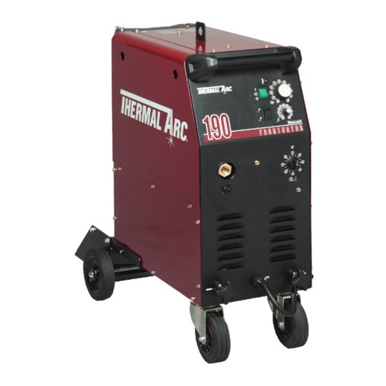
- Page 1 FABRICATOR MIG WELDING MACHINE Art # A-07329 Operating Manual Revision No: AI Issue Date: July 29, 2009 Manual No.: 0-4838 Operating Features:...
- Page 2 YOU ARE IN GOOD COMPANY! The Brand of Choice for Contractors and Fabricators Worldwide. Thermal Arc is a Global Brand of Arc Welding Products for Thermadyne Industries Inc. We manufacture and supply to major welding industry sectors worldwide including; Manufacturing, Construction, Mining, Automotive, Aerospace, Engineering, Rural and DIY/Hobbyist.
- Page 3 While the information contained in this Manual represents the Manufacturer's best judgement, the Manufacturer assumes no liability for its use. Fabricator 190 MIG Welding Machine Instruction Manual Number 0-4838 for: Package System Part Number W1001500...
-
Page 4: Table Of Contents
2.10 MIG Gun Specifications .................. 2-3 2.11 Options and Accessories ................2-3 2.12 Power Supply Specifications ................2-4 2.13 Wire Drive Specifications ................2-5 2.14 Fabricator 190 Package System Contents ............2-5 SECTION 3: INSTALLATION ..................3-1 3.01 Environment ....................3-1 3.02 Location ...................... - Page 5 TABLE OF CONTENTS (continued) TABLE OF CONTENTS SECTION 4: OPERATION ................... 4-1 4.01 Inside Panel ....................4-1 4.02 Power Supply Front Panel ................4-2 4.03 TWECO Weldskill MIG Gun ................4-4 4.04 Installing A New Wire Conduit ................ 4-5 4.05 MIG Gun Maintenance ..................4-6 4.06 Basic Welding Technique ................
-
Page 7: Safety Instructions And Warnings
FABRICATOR 190 WELDING MACHINE SECTION 1: SAFETY INSTRUCTIONS AND WARNINGS WARNING PROTECT YOURSELF AND OTHERS FROM POSSIBLE SERIOUS INJURY OR DEATH. KEEP CHILDREN AWAY. PACEMAKER WEARERS KEEP AWAY UNTIL CONSULTING YOUR DOCTOR. DO NOT LOSE THESE INSTRUCTIONS. READ OPERATING/INSTRUCTION MANUAL BEFORE INSTALLING, OPERATING OR SERVICING THIS EQUIPMENT. - Page 8 FABRICATOR 190 WELDING MACHINE 3. Use protective screens or barriers to protect others from flash and glare; warn others not to watch the arc. WARNING 4. Wear protective clothing made from durable, flame-resistant material (wool and leather) and foot protection.
- Page 9 FABRICATOR 190 WELDING MACHINE 2. If used in a closed area, vent engine exhaust outside and away from any building air intakes. WARNING WARNING FLYING SPARKS AND HOT METAL can cause injury. Chipping and grinding cause flying metal. As welds cool, they can throw off slag.
-
Page 10: Principal Safety Standards
FABRICATOR 190 WELDING MACHINE 1.02 Principal Safety Standards Safety in Welding and Cutting, ANSI Standard Z49.1, from American WARNING Welding Society, 550 N.W. LeJeune Rd., Miami, FL 33126. Safety and Health Standards, OSHA 29 CFR 1910, from Superintendent STEAM AND PRESSURIZED HOT COOLANT can burn of Documents, U.S. -
Page 11: Symbol Chart
FABRICATOR 190 WELDING MACHINE 1.03 Symbol Chart Note that only some of these symbols will appear on your model. Wire Feed Function Single Phase Wire Feed Towards Workpiece With Three Phase Output Voltage Off. Three Phase Static Frequency Converter- Welding Gun... -
Page 12: Precautions De Securite En Soudage A L'arc
FABRICATOR 190 WELDING MACHINE 1.04 Precautions De Securite En Soudage A L’arc MISE EN GARDE LE SOUDAGE A L’ARC EST DANGEREUX PROTEGEZ-VOUS, AINSI QUE LES AUTRES, CONTRE LES BLESSURES GRAVES POSSIBLES OU LA MORT. NE LAISSEZ PAS LES ENFANTS S’APPROCHER, NI LES PORTEURS DE STIMULATEUR CARDIAQUE (A MOINS QU’ILS N’AIENT CONSULTE UN MEDECIN). CONSERVEZ CES INSTRUCTIONS. - Page 13 FABRICATOR 190 WELDING MACHINE AVERTISSEMENT AVERTISSEMENT LES VAPEURS ET LES FUMEES SONT DANGEREUSES LE RAYONNEMENT DE L’ARC PEUT BRÛLER LES YEUX POUR LA SANTE. ET LA PEAU; LE BRUIT PEUT ENDOMMAGER L’OUIE. Le soudage dégage des vapeurs et des fumées L’arc de soudage produit une chaleur et des rayons...
- Page 14 FABRICATOR 190 WELDING MACHINE 7. Ne soudez des tôles galvanisées ou plaquées au plomb ou au cadmium que si les zones à souder ont été grattées à fond, que si AVERTISSEMENT l’espace est bien ventilé; si nécessaire portez un respirateur à ad- duction d’air.
-
Page 15: Principales Normes De Securite
FABRICATOR 190 WELDING MACHINE Les accumulateurs contiennent de l’électrolyte acide et 1. Utilisez l’équipement à l’extérieur dans des aires ouvertes et bien ventilées. dégagent des vapeurs explosives. 2. Si vous utilisez ces équipements dans un endroit confiné, les 1. Portez toujours un écran facial en travaillant sur un accumu-lateur. -
Page 16: Graphique De Symbole
FABRICATOR 190 WELDING MACHINE 1.07 Graphique de Symbole Seulement certains de ces symboles apparaîtront sur votre modèle. Déroulement du Fil Sous Tension Mono Phasé Alimentation du Fil Vers la Pièce de Fabrication Hors Tension Trois Phasé Hors Tension Tri-Phase Statique... -
Page 17: Introduction
Include the Owner’s Manual number and equipment identification numbers. Electronic copies of this manual can also be downloaded at no charge in Acrobat PDF format by going to the Thermal Arc web site listed below and clicking on the Literature Library link: http://www.thermalarc.com Manual No. 0-4838... -
Page 18: General Information
FABRICATOR 190 WELDING MACHINE 2.04 General Information 2.06 Protective Filter Lenses The Fabricator 190 is a semiautomatic Gas Metal Arc Protective filter lenses are provided to reduce the intensity Welder (GMAW/FCAW-commonly MIG) with an integrated of radiation entering the eye thus filtering out harmful wire feed unit. -
Page 19: User Responsibility
190 amps, for 1 minute and 30 seconds out of every 10 minute period. During the other 8 minutes 30 seconds of the 10 minute period the Fabricator 190 must idle and be allowed to cool. The thermal cutout will operate if the duty cycle is exceeded. -
Page 20: Power Supply Specifications
FABRICATOR 190 WELDING MACHINE 2.12 Power Supply Specifications Package System Part Number W1001500 Power Source Part Number 707559 Power Source Weight 123lb (56kg) Power Source Dimensions HxWxD 33 x 16.3 x 34.7” (including wheels and cylinder carrier) (838 x 414 x 866mm) Number of Phases 1∅... -
Page 21: Wire Drive Specifications
44 lb, 33 lb, 10 lb, 8” and 12” wire spool sizes 2.14 Fabricator 190 Package System Contents Fabricator 190 Package System Contents Fabricator 190 Power Source with Integrated Wirefeeder Factory Fitted Wheeling Kit Factory Fitted Single Cylinder Rack Factory Fitted Primary Power Cable 10 AWG, 10ft (3m) with Plug... - Page 22 FABRICATOR 190 WELDING MACHINE INTRODUCTION Manual No. 0-4838...
-
Page 23: Installation
INSTALLATION 3.02 Location 3.01 Environment Be sure to locate the Power Supply according to the The Fabricator 190 is NOT designed for use in following guidelines: environments with increased hazard of electric shock. In areas, free from moisture and dust. -
Page 24: Mains Supply Voltage Requirements
3.05 Alternative Mains Supply Voltages WARNING The Fabricator 190 input power supply lead should be replaced with leads as specified in Table 3-2 when the Fabricators input power supply voltage is changed. The Power Supply is suitable for use on the following input power supply voltages:... -
Page 25: Quick Set Up
FABRICATOR 190 WELDING MACHINE 3.06 Quick Set Up 7. Fit the electrode wire spool to the wire reel hub located behind the electrode wire compartment door. CAUTION 8. Fit the TWECO Weldskill MIG gun and trigger wires through/to the front of the unit. -
Page 26: Installation Of Shielding Gas (Gmaw) Process
FABRICATOR 190 WELDING MACHINE 3.07 Installation of Shielding Gas Adjusting Regulator (GMAW) Process Adjust control knob of regulator to the required flow rate, indicated on gauge dial. (Refer to Figure 3-1 and data charts Refer to Figure 3-2. Approx. 20 CFH. - Page 27 FABRICATOR 190 WELDING MACHINE Shielding Regulator and “Cracking” Flow Meter Shielding Shielding Shielding Art # A-07401 Gas Hose Figure 3-2: Gas Cylinder Installation Manual No. 0-4838 INSTALLATION...
-
Page 28: Attaching The Gun And Cable Assembly To The Power Source
FABRICATOR 190 WELDING MACHINE 3.08 Attaching the Gun and Cable Assembly to the Power Source The Fabricator 190 is supplied with a Tweco Weldskill gun 190 10217 air-cooled torch. The Weldskill gun is designed with an ergonomic handle and fewer parts to cause performance problems. - Page 29 FABRICATOR 190 WELDING MACHINE Art # A-07339 Front Panel Access Hole Trigger Receptacle Figure 3-4: Route Gun Cable Through Access Hole and Connect Trigger Loosen Thumbscrew Art: A-07601 Tighten Thumbscrew Figure 3-5: Mount Gun Cable to Adapter Socket Manual No. 0-4838...
-
Page 30: Feedrolls
FABRICATOR 190 WELDING MACHINE 3.09 Feedrolls A feedroll consists of two different sized grooves. As de- livered from the factory, the feedroll is installed for .023” (0.6mm). When the feedroll is installed, the visibly marked size re- fers to the groove which will be in use. -
Page 31: Installing Wire Spool
FABRICATOR 190 WELDING MACHINE 3.10 Installing Wire Spool Installation of 8” (203mm) spool 1. Remove the spool retaining pin (6) from spool hub (7). 2. Fit the spool (5) onto the spool hub (7). 3. Ensure that the drive pin engages the mating hole in the spool. -
Page 32: Inserting Wire Into The Feedhead And Welding Gun
FABRICATOR 190 WELDING MACHINE CAUTION 3.11 Inserting Wire into the Feedhead and Welding Gun Use care in handling the spooled wire as it will tend to “unravel” when loosened from the spool. Grasp the end of the wire firmly, and WARNING don’t let go of it. - Page 33 FABRICATOR 190 WELDING MACHINE Art # A-07568 Feedroll kit consists of idler roll and drive roll Figure 3-9: Opening Pressure Arm and Inserting Wire Art # A-07570 Wire Threaded Through Feedroll Figure 3-10: Wire Installed Manual No. 0-4838 3-11 INSTALLATION...
-
Page 34: Polarity Changeover
FABRICATOR 190 WELDING MACHINE 3.12 Polarity Changeover WARNING ELECTRIC SHOCK CAN KILL! Make certain the machine is unplugged from the power receptacle. Do not plug machine in until told to do so in these instructions As delivered from the factory, the output polarity is connected for DCEP (reverse polarity). - Page 35 FABRICATOR 190 WELDING MACHINE Art # A-07571 Terminal Knob Figure 3-11: Remove Terminal Knobs Art # A-07340 DCEN DCEP Polarity Polarity Terminal Terminal Terminal Polarity Cable Connect the work cable to the vacant terminal Figure 3-12: Terminal Polarity Setting Manual No. 0-4838...
- Page 36 FABRICATOR 190 WELDING MACHINE INSTALLATION 3-14 Manual No. 0-4838...
-
Page 37: Operation
FABRICATOR 190 WELDING MACHINE SECTION 4: OPERATION WARNING The electrode wire will be at welding voltage potential while it is being fed through the system. 4.01 Inside Panel 1. Burnback Control Knob: Burnback time is the difference between the wirefeed motor stopping and switching off of the welding current. -
Page 38: Power Supply Front Panel
FABRICATOR 190 WELDING MACHINE 4.02 Power Supply Front Panel Weldskill Art # A-07476 Figure 4-2: Fabricator 190 Front Panel OPERATION Manual No. 0-4838... - Page 39 When Trigger 4-pin receptacle is used to connect the two the MIG gun trigger switch is released welding wires from the MIG gun to the Fabricator 190. Only ceases. pins A and B are used for this. To make connections,...
-
Page 40: Tweco Weldskill Mig Gun
Figure 4-3: Torch Trigger Receptacle Pin-out 4.03 TWECO Weldskill MIG Gun The TWECO Weldskill MIG Gun fitted to the FABRICATOR 190 offers robust construction, unparalleled reliability and easy replacement of consumable parts. The TWECO Weldskill MIG Gun has an operating capacity in excess of the capacity of the FABRICATOR and can be expected to give trouble free service. -
Page 41: Installing A New Wire Conduit
2 Start from the Connector Plug end of the assembly and begin pushing the Wire Conduit through the Contact your Thermal Arc distributor to order TWECO Connector Plug, cable assembly and into the gun. If replacement parts, options and accessories. For... -
Page 42: Mig Gun Maintenance
FABRICATOR 190 WELDING MACHINE 3. Replace the Gas Diffuser and Insulator. 4. Replace the Contact Tip and Nozzle. CAUTION Do not over-tighten the allen screw as this will distort the Wire Conduit and lead to wire feedability problems. CONDUCTOR TUBE... -
Page 43: Basic Welding Technique
FABRICATOR 190 WELDING MACHINE 4.06 Basic Welding Technique Setting of the Power Supply The setting of the Fabricator requires some practice by the operator, the welding Power Supply having two control settings that have to balance. These are the Wire Speed control and the Voltage Control switches. The welding current is determined by the Wire Speed control, the current will increase with increased Wire Speed, resulting in a shorter arc. - Page 44 FABRICATOR 190 WELDING MACHINE Distance from the MIG Gun Nozzle to the Work Piece The electrode stick out from the MIG gun nozzle should be between 5/64”(2.0mm) to 13/64”(5.0mm). This distance may vary depending on the type of joint that is being welded.
-
Page 45: Technical Tips
FABRICATOR 190 WELDING MACHINE 4.07 Technical Tips Output Voltage Control Switch to 8 Wirespeed Control to between 5 to 8 Reduce Porosity in the Weld Metal Mode Selector Switch to Spot • Weld in still air to ensure gas coverage •... -
Page 46: Welding Setting Selection Guide
FABRICATOR 190 WELDING MACHINE 4.09 Welding Setting Selection Guide Material T ype Wire T ype Shielding Gas Wire Size and Flow Rate (Diameter) Art # A-07448 .023” (0.6mm) 100% CO .030” (0.8mm) 25cfh .035” (0.9mm) .023” (0.6mm) Solid 75% Ar... - Page 47 FABRICATOR 190 WELDING MACHINE Voltage THICKNESS Step Wire Speed 22 ga. (0.8mm) 20 ga. (0.9mm) 18 ga. (1.2mm) 16 ga. (1.6mm) 1/8” (3.2mm) 3/16” (5.0mm) 1/4” (6.4mm) 5/16” (8.0mm) 2.25 2.75 2.25 2.75 3.25 3.75 4.75 1.25 2.75 4.25 4.75 3.25...
- Page 48 FABRICATOR 190 WELDING MACHINE NOTES OPERATION 4-12 Manual No. 0-4838...
-
Page 49: Service
FABRICATOR 190 WELDING MACHINE SECTION 5: SERVICE To clean the Power Supply, disconnect it from the mains 5.01 Routine Maintenance & Inspection supply voltage then open the enclosure and use a vacuum cleaner to remove any accumulated dirt and dust. The The only routine maintenance required for the Fabricator Power Supply should also be wiped clean. - Page 50 FABRICATOR 190 WELDING MACHINE Maintain more often Warning! if used under severe Disconnect input power before maintaining. conditions Each Use Visual check of torch Visual check of Consumable parts regulator and pressure Weekly Visually inspect the torch Visually inspect the Wire...
-
Page 51: Basic Troubleshooting
7. Maintain the MIG torch in good working order. If major components are faulty, then the Power Supply should be returned to an Accredited Thermal Arc Service a. Ensure that the gas holes are not blocked and Agent for repair. - Page 52 FABRICATOR 190 WELDING MACHINE 6. Incorrect or worn contact tip. 2. Inconsistent wire feed Wire feeding problems can be reduced by checking the a. The contact tip transfers the weld current to following points: the electrode wire. If the hole in the contact tip is to large then arcing may occur inside the 1.
-
Page 53: Welding Problems
FABRICATOR 190 WELDING MACHINE 5.04 Welding Problems FAULT CAUSE REMEDY A. Undercut. 1. Welding arc voltage Reduce voltage by reducing the output too high. voltage control switch position or increase the wire speed. 2. Incorrect torch Adjust angle angle 3. Excessive heat... - Page 54 6. Weld speed too fast Reduce weld speed. B. Cold weld puddle. 1. Faulty rectifier unit Have an Accredited Thermal Arc Service Agent to test then replace the faulty component. 2. Loose welding cable Check all welding cable connections.
-
Page 55: Power Supply Problems
FABRICATOR 190 WELDING MACHINE 5.05 Power Supply Problems FAULT CAUSE REMEDY Switch the ON/OFF Power A. Indicator light in the ON/OFF Power 1. The ON/OFF Power Switch on. Switch is illuminated but welding Switch is off. arc can not be established. - Page 56 FABRICATOR 190 WELDING MACHINE NOTES MANUAL GMAW WELDING Manual No. 0-4838...
-
Page 57: Appendix 1: Options And Accessories
Tweco® Spraymaster 12ft MS212-3545 ACCESSORIES MIG gun control lead & 4 pin plug MSAK-354 Connection lead between TWECO MIG guns & Fabricator 190 Medalist™ 1400 Series, HRF Flowmeter Regulator, Argon- Victor Regulator/Flowmeter Mixed Gases 0781-2723 Argon/CO2 mix gases Victor Regulator/Flowmeter CO2 0781-2725 Medalist™... -
Page 58: Appendix 2: Power Supply Circuit Diagram
FABRICATOR 190 WELDING MACHINE APPENDIX 2: POWER SUPPLY CIRCUIT DIAGRAM NOTE: Re-use this jumper when replacing the 7978050 Control PCB March 17, 2006... - Page 59 FABRICATOR 190 WELDING MACHINE Wirespeed 1K JB/3 Art # A-07406_AB FABRICATOR 190 SYSTEM SCHEMATIC SWITCH 2 SWITCH POSITION March 17, 2006...
-
Page 61: Limited Warranty
No employee, agent, or representative of thermal arc is authorized to change this warranty in any way or grant any other warranty, and thermal arc shall not be bound by any such attempt. -
Page 62: Warranty Schedule
WARRANTY SCHEDULE This information applies to Thermal Arc products that were purchased in the USA and Canada. March, 2008 ENGINE DRIVEN WELDERS ARRANTY ERIOD ABOR Scout, Raider, Explorer Original Main Power Stators and Inductors .................. 3 years 3 years Original Main Power Rectifiers, Control P.C. Boards ..............3 years... -
Page 63: Global Customer Service Contact Information
GLOBAL CUSTOMER SERVICE CONTACT INFORMATION Thermadyne USA Thermadyne Asia Sdn Bhd 2800 Airport Road Lot 151, Jalan Industri 3/5A Denton, Tx 76207 USA Rawang Integrated Industrial Park - Jln Batu Arang 48000 Rawang Selangor Darul Ehsan Telephone: (940) 566-2000 West Malaysia 800-426-1888 Telephone: 603+ 6092 2988 Fax: 800-535-0557... - Page 64 World Headquarters Thermadyne Holdings Corporation Suite 300, 16052 Swingley Ridge Road St. Louis, MO 63017 Telephone: (636) 728-3000 FAX: (636) 728-3010 Email: sales@thermalarc.com www.thermalarc.com...
Need help?
Do you have a question about the FABRICATOR 190 and is the answer not in the manual?
Questions and answers