
Related Manuals for Thermal Arc 161 S


Summary of Contents for Thermal Arc 161 S
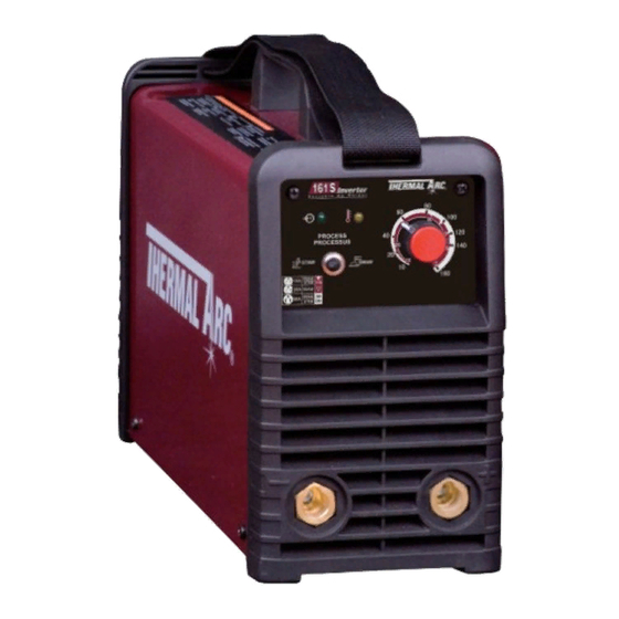
- Page 1 161 S THERMAL ARC ® InvERTER ARC WELdER Art# A-09194_AB Operating Manual Revision: AC Issue Date: September 29, 2010 Manual No.: 0-5073 Operating Features:...
- Page 2 YOU ARE IN GOOD COMPANY! The Brand of Choice for Contractors and Fabricators Worldwide. Thermal Arc is a Global Brand of Arc Welding Products for Thermadyne Industries Inc. We manufacture and supply to major welding industry sectors worldwide including; Manufacturing, Construction, Mining, Automotive, Aerospace, Engineering, Rural and DIY/Hobbyist.
- Page 3 Operating Manual Number 0-5073 for: Thermal Arc 161 S Power Source Arc Welder Part No. W1003600 Thermal Arc 161 S System with Stick Kit & Case Part No. W1003602 Thermal Arc 161 S System with Stick/TIG Kit & Case Part No. W1003603 Published by: Thermadyne Industries Inc.
-
Page 4: Table Of Contents
TABLE OF CONTENTS SECTION 1:SAFETY INSTRUCTIONS AND WARNINGS ..........1-1 1.01 Arc Welding Hazards ..................1-1 1.02 General Safety Information for Victor CS Regulator .......... 1-4 1.03 Principal Safety Standards ................1-5 1.04 Symbol Chart ....................1-6 1.05 Precautions De Securite En Soudage A L’arc ..........1-7 1.06 Dangers relatifs au soudage à... - Page 5 TABLE OF CONTENTS SECTION 4:OPERATION ..................4-1 4.01 Front Panel ..................... 4-1 4.02 Welding Current Control Explanation .............. 4-2 4.03 STICK (SMAW) Electrode Polarity..............4-3 4.04 Effects of Stick Welding Various Materials ............4-3 4.05 GTAW Electrode Polarity ................. 4-4 4.06 Guide for Selecting Filler Wire ................
- Page 6 • Operating manual Art# A-09755 Thermal Arc 161S TIG/Stick System Part Number W1003603 • Thermal Arc 161 S power supply in toolbox • 17V TIG torch, 12.5ft (3.8m) with accessory kit • Tweco electrode holder, 13ft (4m) lead • Tweco ground clamp, 10ft (3.1m) lead •...
-
Page 7: Section 1:Safety Instructions And Warnings
SAFETY INSTRUCTIONS THERMAL ARC 161 S SECTION 1: SAFETY INSTRUCTIONS AND WARNINGS WARNING PROTECT YOURSELF AND OTHERS FROM POSSIBLE SERIOUS INJURY OR DEATH. KEEP CHILDREN AWAY. PACEMAKER WEARERS KEEP AWAY UNTIL CONSULTING YOUR DOCTOR. DO NOT LOSE THESE INSTRUCTIONS. READ OPERATING/INSTRUCTION MANUAL BEFORE INSTALLING, OPERATING OR SERVICING THIS EQUIPMENT. -
Page 8: Safety Instructions
THERMAL ARC 161 S SAFETY INSTRUCTIONS WARNING WARNING WELDING can cause fire or explosion. FUMES AND GASES can be hazardous to your health. Sparks and spatter fly off from the welding arc. The flying Welding produces fumes and gases. Breathing these sparks and hot metal, weld spatter, hot workpiece, and fumes and gases can be hazardous to your health. - Page 9 SAFETY INSTRUCTIONS THERMAL ARC 161 S WARNING WARNING FLYING SPARKS AND HOT METAL can cause injury. ENGINE FUEL can cause fire or explosion. Chipping and grinding cause flying metal. As welds cool, Engine fuel is highly flammable. they can throw off slag.
-
Page 10: General Safety Information For Victor Cs Regulator
THERMAL ARC 161 S SAFETY INSTRUCTIONS 1.02 General Safety Information for Victor CS Regulator WARNING Fire Prevention STEAM AND PRESSURIZED HOT COOLANT can burn Welding and cutting operations use fire or combustion as a basic tool. The process is very useful when properly controlled. However, face, eyes, and skin. -
Page 11: Principal Safety Standards
SAFETY INSTRUCTIONS THERMAL ARC 161 S D Personal Protection 3. Store empty cylinders away from full cylinders. Mark them “EMPTY” and close the cylinder valve. Gas flames produce infrared radiation which may have a harmful effect on the skin and especially on the eyes. Select goggles or a mask with 4. -
Page 12: Symbol Chart
THERMAL ARC 161 S SAFETY INSTRUCTIONS 1.04 Symbol Chart Note that only some of these symbols will appear on your model. Wire Feed Function Single Phase Wire Feed Towards Workpiece With Three Phase Output Voltage Off. Three Phase Static Frequency Converter-... -
Page 13: Precautions De Securite En Soudage A L'arc
SAFETY INSTRUCTIONS THERMAL ARC 161 S 1.05 Precautions De Securite En Soudage A L’arc MISE EN GARDE LE SOUDAGE A L’ARC EST DANGEREUX PROTEGEZ-VOUS, AINSI QUE LES AUTRES, CONTRE LES BLESSURES GRAVES POSSIBLES OU LA MORT. NE LAISSEZ PAS LES ENFANTS S’APPROCHER, NI LES PORTEURS DE STIMULATEUR CARDIAQUE (A MOINS QU’ILS N’AIENT CONSULTE UN MEDECIN). - Page 14 THERMAL ARC 161 S SAFETY INSTRUCTIONS 1. Portez une casque de soudeur avec filtre oculaire de nuance ap- 1. Eloignez la tête des fumées pour éviter de les respirer. propriée (consultez la norme ANSI Z49 indiquée ci-après) pour 2. A l’intérieur, assurez-vous que l’aire de soudage est bien ventilée vous protéger le visage et les yeux lorsque vous soudez ou que...
- Page 15 SAFETY INSTRUCTIONS THERMAL ARC 161 S AVERTISSEMENT AVERTISSEMENT LE SOUDAGE PEUT CAUSER UN INCENDIE OU UNE LES BOUTEILLES ENDOMMAGEES PEUVENT EX- EXPLOSION PLOSER L’arc produit des étincellies et des projections. Les parti- Les bouteilles contiennent des gaz protecteurs sous cules volantes, le métal chaud, les projections de soudure haute pression.
-
Page 16: Informations Générales De Sécurité
THERMAL ARC 161 S SAFETY INSTRUCTIONS 2. Ne faites pas le plein en fumant ou proche d’une source d’étincelles ou d’une flamme nue. 3. Si c’est possible, laissez le moteur refroidir avant de faire le plein AVERTISSEMENT de carburant ou d’en vérifier le niveau au début du soudage. - Page 17 SAFETY INSTRUCTIONS THERMAL ARC 161 S AVERTISSEMENT AVERTISSEMENT N’effectuez JAMAIS d’opérations de soudage sur un Mettez en pratique les procédures de sécurité et de récipient qui a contenu des liquides ou vapeurs toxiques, mode opératoire suivantes à chaque fois que vous combustibles ou inflammables.
-
Page 18: Principales Normes De Securite
THERMAL ARC 161 S SAFETY INSTRUCTIONS AVERTISSEMENT N’UTILISEZ PAS la bouteille si vous trouvez de l’huile, de la graisse ou des pièces endommagées. Informez immédiatement votre fournisseur de’ gaz de cet état. 6. Ouvrez et fermez momentanément la vanne de la bouteille, délogeant ainsi d’éventu lIes poussières ou saletés. -
Page 19: Graphique De Symbole
SAFETY INSTRUCTIONS THERMAL ARC 161 S 1.09 Graphique de Symbole Seulement certains de ces symboles apparaîtront sur votre modèle. Déroulement du Fil Sous Tension Mono Phasé Alimentation du Fil Vers la Pièce de Fabrication Hors Tension Trois Phasé Hors Tension... - Page 20 This page left blank intentionally.
-
Page 21: Section 2:Introduction
INTRODUCTION THERMAL ARC 161 S SECTION 2: INTRODUCTION 2.01 How to Use This Manual 2.04 Description This Operating Manual usually applies to the part numbers This compact inverter welding machine has infinitely listed on page i. If none are underlined, they are all covered adjustable welding current from 10 to 160 amps. -
Page 22: Specifications
(Based on Article 630, National Electrical Code) Thermal Arc continuously strives to produce the best product possible and therefore reserves the right to change, improve or revise the speci- fications or design of this or any product without prior notice. Such updates or changes do not entitle the buyer of equipment previously sold or shipped to the corresponding changes, updates, improvements or replacement of such items. -
Page 23: Section 3:Installation
• Place at a distance of 12” (300mm) or more from walls or similar that could restrict natural air flow for cooling WARNING Thermal Arc advises that this equipment be electrically connected by a qualified electrician. 3.03 Electrical Input Connections WARNING ELECTRIC SHOCK can kill;... - Page 24 THERMAL ARC 161 S INSTALLATION for information about the type of electrical service available, how proper connections should be made, and inspection required. The line disconnect switch provides a safe and convenient means to completely remove all electrical power from the welding power supply whenever necessary to inspect or service the unit.
- Page 25 INSTALLATION THERMAL ARC 161 S Input Power Each unit incorporates an INRUSH circuit. When the MAIN CIRCUIT SWITCH is turned on, the inrush circuit provides pre-charging for the input capacitors. A relay in the Power Control Assembly (PCA) will turn on after the input capacitors...
-
Page 26: Electromagnetic Compatibility
THERMAL ARC 161 S INSTALLATION 3.04 Electromagnetic Compatibility The size of the surrounding area to be considered will depend on the structure of the building and other activities that are taking place. The surrounding area may extend beyond the boundaries of the premises. -
Page 27: Setup For Welding
INSTALLATION THERMAL ARC 161 S 3.05 Setup for Welding 5. Earthing of the Work Piece Where the work piece is not bonded to earth for NOTE electrical safety, nor connected to earth because of its Conventional operating procedures apply size and position, e.g. ship’s hull or building steelwork, when using the Welding Power Source, i.e. -
Page 28: Stick (Smaw) Setup
THERMAL ARC 161 S INSTALLATION 3.06 STICK (SMAW) Setup Set Welding Current as specified by the Set Process Selection Electrode Manufacturer. Switch to STICK. Negative Output Positive Output Terminal Terminal (Dinse™ 50) (Dinse™ 50) Art#: A-08602_AB Figure 3-2: Setup for STICK (SMAW) Welding STICK (SMAW) Mode Sequence of Operation 3. -
Page 29: Lift Tig (Gtaw) Setup
INSTALLATION THERMAL ARC 161 S 3.07 LIFT TIG (GTAW) Setup Set Process Selection Switch to LIFT TIG. Set Welding Current as specified by the Electrode Manufacturer. Negative Output Terminal (Dinse™ 50) Secure the gas cylinder in an Positive Output upright position by chaining it... -
Page 30: Victor Regulator
THERMAL ARC 161 S INSTALLATION 2. The regulator body will be stamped “IN” or “HP” 9. Set the “Process Selection Switch” to LIFT TIG at the inlet port. Attach the inlet port to the system supply pressure connection. 10. Set the weld current control knob to the desired amperage. - Page 31 INSTALLATION THERMAL ARC 161 S 6. Carefully inspect the regulator for damaged 9. Slowly and carefully open the cylinder valve threads, dirt, dust, grease, oil, or other flammable (Figure 3-6) until the maximum pressure shows substances. Remove dust and dirt with a clean on the high pressure gauge.
-
Page 32: Leak Testing The System
THERMAL ARC 161 S INSTALLATION 3.09 Leak Testing the System 3.10 When You Finish Using the Regulator Leak test the system before putting into operation. 1. Be sure that there is a valve in the downstream 1. Close the cylinder valve. -
Page 33: Section 4:Operation
If the Warning Indicator flashes on and off then the primary current into the main transformer has been ex- Front Panel ceeded. Have an Accredited Thermal Arc Service Provider The welding power source is protected by a self re-setting inspect then repair the welder. -
Page 34: Welding Current Control Explanation
THERMAL ARC 161 S OPERATION 4.02 Welding Current Control Output Scale for 115V Explanation The inside number scale identifies the available 15 Amp Outlet output weld current for STICK or LIFT TIG weld modes. The mains power 15 Amp circuit breaker or fuse should... -
Page 35: Stick (Smaw) Electrode Polarity
OPERATION THERMAL ARC 161 S 4.03 STICK (SMAW) Electrode Polarity Cast Iron Most types of cast iron, except white iron, are weldable. Stick electrodes are generally connected to the "+" Posi- White iron, because of its extreme brittleness, generally tive Output Terminal and the work lead to the "−" Nega- cracks when attempts are made to weld it. -
Page 36: Gtaw Electrode Polarity
THERMAL ARC 161 S OPERATION 4.05 GTAW Electrode Polarity Connect the TIG torch to the "-" Negative Output Terminal and the work lead to the "+" Positive Output Terminal for direct current straight polarity. Direct current straight polarity is the most widely used polarity for DC TIG welding. It allows limited wear of the electrode since 70% of the heat is concentrated at the work piece. -
Page 37: Tig Welding Parameters For Steel
OPERATION THERMAL ARC 161 S 4.10 TIG Welding Parameters for Steel DC Current Stainless Base Metal Electrode Filler Rod Argon Gas Flow Mild Steel Steel Thickness Diameter Diameter Rate Joint / Type 35-45 20-30 Butt/Corner 0.040" 1/16" 10 CFH 0.040"... -
Page 38: Welding Position
THERMAL ARC 161 S OPERATION 4.12 Welding Position The electrodes dealt with in this publication can be used in most positions, i.e. they are suitable for welding in flat, horizontal, vertical and overhead positions. Numerous applications call for welds to be made in positions intermediate between these. -
Page 39: Joint Preparations
OPERATION THERMAL ARC 161 S 4.13 Joint Preparations In many cases, it will be possible to weld steel sections without any special preparation. For heavier sections and for repair work on castings, etc., it will be necessary to cut or grind an angle between the pieces being joined to ensure proper penetration of the weld metal and to produce sound joints. -
Page 40: Arc Welding Technique
THERMAL ARC 161 S OPERATION 4.14 Arc Welding Technique Another difficulty you may meet is the tendency, after the arc is struck, to withdraw the electrode so far that the arc A Word to Beginners is broken again. A little practice will soon remedy both of these faults. -
Page 41: Making Welded Joints
OPERATION THERMAL ARC 161 S 4.19 Making Welded Joints Heavy plate will require several runs to complete the joint. After completing the first run, chip the slag out and clean Having attained some skill in the handling of an electrode, the weld with a wire brush. - Page 42 THERMAL ARC 161 S OPERATION Art # A-07701 Art # A-07700 Figure 4-16: Multi-runs in HV fillet weld C. Vertical Welds Figure 4-17: Single run vertical fillet weld 1. Vertical Up Tack weld a three feet length of angle iron to your Art # A-07702 work bench in an upright position.
-
Page 43: Distortion
OPERATION THERMAL ARC 161 S 3. Overhead Welds 4.20 Distortion Apart from the rather awkward position necessary, Distortion in some degree is present in all forms of overhead welding is not much more difficult that welding. In many cases it is so small that it is barely downhand welding. -
Page 44: Overcoming Distortion Effects
THERMAL ARC 161 S OPERATION The metal in the weld area is stretched (plastic deforma- D. Presetting tion), the job may be pulled out of shape by the powerful It is possible in some cases to tell from past experience or... - Page 45 OPERATION THERMAL ARC 161 S Art # A-07710 Figure 4-26: Welding sequence Art # A-07711 Figure 4-27: Step back sequence Art # A-07712 Figure 4-28: Chain intermittent welding Art # A-07713 Figure 4-29: Staggered intermittent welding Manual 0-5073 4-13 4-13...
- Page 46 This Page Intentionally Blank.
-
Page 47: Section 5:Service
SERVICE THERMAL ARC 161 S SECTION 5: SERVICE 5.01 Maintenance and Inspection To clean the unit, open the enclosure and use a vacuum cleaner to remove any accumulated dirt and dust. The unit The only routine maintenance required for the power should also be wiped clean, if necessary;... -
Page 48: Stick (Smaw) Welding Problems
THERMAL ARC 161 S SERVICE 5.02 STICK (SMAW) Welding Problems Description Possible Cause Remedy 1. Gas pockets or voids in weld metal Electrodes are damp. A. Dry electrodes before use. (Porosity). Welding current is too high. B. Reduce welding current. -
Page 49: Tig Welding Problems
SERVICE THERMAL ARC 161 S 5.03 TIG Welding Problems Weld quality is dependent on the selection of the correct consumables, maintenance of equipment and proper welding technique. Description Possible Cause Remedy 1. Excessive bead build-up or poor Welding current is too low... -
Page 50: Power Source Problems
There are extremely dangerous voltages and power levels present inside this product. Do not attempt to repair unless you are an Accredited Thermal Arc Service Agent and you have had training in power mea- surements and troubleshooting techniques. If major complex subassemblies are faulty, then the Welding Power Source must be returned to an Accredited Thermal Arc Service Agent for repair. -
Page 51: Appendix 1: Replacement Parts
APPENDIX THERMAL ARC 161 S APPENDIX 1: REPLACEMENT PARTS Description Part No. Panel,Cover, 161S W7003051 Switch,On/Off,161S W7003053 Panel,Rear,161S W7003054 Fan,24V DC,161,201TS W7003009 Rectifier Bridge, 700V,50A W7003010 Resistor,6 ohm,60W W7003055 PCB Control,161S W7003057 Insulation Sheet,161S W7003060 PCB,Power,161S W7003061 PCB,Front Control,95S,161S W7003047... -
Page 52: Appendix 2: Options And Accessories
THERMAL ARC 161 S APPENDIX APPENDIX 2: OPTIONS AND ACCESSORIES Description Part Number 17V style TIG Torch with 12.5ft lead, gas valve, 50mm dinse connection and accessory kit W4012600 VICTOR AF210-580 Regulator, Argon-CO2 Flowgauge with 5/8" - 18 UNF connection... -
Page 53: Appendix 3: System Schematic
APPENDIX THERMAL ARC 161 S APPENDIX 3: SYSTEM SCHEMATIC Art# A-09196 Manual 0-5073 Appendix... -
Page 54: Limited Warranty
No employee, agent, or representative of Thermal Arc is authorized to change this warranty in any way or grant any other warranty, and Thermal Arc shall not be bound by any such attempt. Correction of non-conformities, in the manner and time provided herein, constitutes fulfillment of thermal’s obligations to purchaser with respect to the product. - Page 55 WARRANTY SCHEDULE This information applies to Thermal Arc products that were purchased in the USA and Canada. January 2009 SAFETY EQUIPMENT ARRANTY ERIOD ABOR Auto-Darkening Welding Helmet (Electronic Lens) 2 year 2 year Harness Assembly 1 Month 1 Month ENGINE DRIVEN WELDERS...
- Page 56 U.S. Customer Care: 800-426-1888 / 800-535-0557 Canada Customer Care: 905-827-4515 / 800-588-1714 • International Customer Care: 940-381-1212 / 940-483-8178 www.thermalarc.com • A Global Cutting & Welding Market Leader ™ W O R L D H E A D Q U A R T E R S : 1 6 0 5 2 S w i n g l e y R i d g e R o a d , S u i t e 3 0 0 •...
Need help?
Do you have a question about the 161 S and is the answer not in the manual?
Questions and answers