
Related Manuals for Paramount Fitness SF-1700


Summary of Contents for Paramount Fitness SF-1700
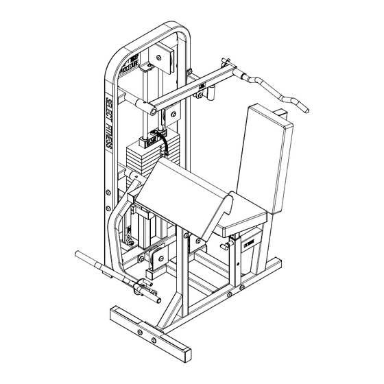
- Page 1 SELECT FITNESS CIRCUIT SF-1700 BICEPS/TRICEPS ASSEMBLY MANUAL AM-SF-1700 Rev 06/02...
- Page 2 AFETY 1. Review and understand all of the warning labels affixed to the machines and the facility safety sign. Replace any warning label at first sign of wear. Labels and the Facility Safety Sign may be obtained from Paramount free of charge. 2.
-
Page 3: Maintenance
MAINTENANCE 1. Frames: Wipe all machines down with a damp cloth and dry completely each day. This includes painted, chrome parts and upholstered pads. 2. Painted/chrome parts: Use Simple Green or similar cleaner for light dirt and grime. Use TurtleWax® Polishing Compound or a good car polish to remove heavier dirt and grease as well as for polishing. - Page 4 TOOLS REQUIRED: WRENCH SOCKET PUNCH RUBBER SOCKET 7/16” (11mm) 7/16” (11mm) ALLEN WRENCH 7/16” (11mm) MALLET 9/16” (14mm) WRENCH 9/16” (14mm) 3/4” (19mm) 5/32” (4mm) 3/4” (19mm) 7/8” (22mm) 3/16” (5mm) 15/16” (24mm) SF-1700CTN1: 1701515 9000801X (2) 8001525 9099780X 1701510X 1701565X 0101599 1701591...
- Page 5 SF-1700CTN2: 8093040 1701545X 1701540X 1701520X 1701560 1701531 1701529 1701550X 2299HND001 45 5/8” (116 cm) 1701600 4000PLY000 138 3/4” (352 cm) 1701505 1701610 HW-1701-1 8093006X HW-1701-2 HW-1701-3...
-
Page 6: Hardware Bag
HARDWARE BAG 1701-2: B1295 (2) B 582 (2) B 682 (6) B 447 B 1136 (5) B 900 (3) B1117 (2) B 921 (6) B 898 B 1182 (2) B 460 HARDWARE BAG 1701-1: 3/8-16 x 1 1/4 HHCS 3/8-16 x 1 BHCS 3/8 Metal Base 3/8 Black Washer 3/8 Lock Washer... - Page 7 MINIMUM FLOOR AREA REQUIRED: MACHINE WEIGHT (NOT INCLUDING WEIGHT OF USER): W/170 LB STACK 443 LBS W/250 LB STACK 523 LBS 56” SHROUD OPTION +30LB (142cm) 92” (234cm) IN USE Height = 60 inches (152cm) 47” (119cm) 83” (211cm) IN USE NOTE: THIS MACHINE IS DESIGNED FOR USERS WEIGHING 300LB OR LESS HARDWARE MEASUREMENT GUIDE:...
- Page 8 TOP VIEW Pulley Housing 1701510X 8093040 1701515 1701520X H (2) D (2) NOTE: WHEN INSTALLING HARDWARE, TIGHTEN BY HAND ONLY UNTIL ALL COMPONENTS ARE ASSEM- BLED. BOLT HEADS SHOULD FACE TO OUTSIDE OF MACHINE WHERE POSSIBLE. BE SURE ALL HARDWARE IS TIGHT BEFORE USING MACHINE.
- Page 9 Diagram A 1701545X Diagram B 1701540X 8093006X D 707 (2) C 747 (2) C 675C (2) C 752 (2) Diagram A D 875 D 591 (ADD ADDITIONAL THRUST BEARING IF REQUIRED) D 591 1701531 5 13/16” Align Holes! Diagram B 1701570x D 840...
- Page 10 Diagram C G (2) 1701560 1701550X See Diagram D 2299HND001 D 836 D 875 Align Holes! 1701529 Diagram C D1041 C 732 C 653 C 628 D 706 D 588 Diagram D (To fill gap if required)
- Page 11 S (2) 8001520X 8001525 0101599 N (2) 0101520X B1295 (2) A (2) 1701565X C 658 (2) 1701591 C 754B (4) C 955A (2) C 766A (2) C 955 (2)
-
Page 12: Weight Stack Installation
WEIGHT STACK INSTALLATION Review the equipment order to determine P/N: B1602 the weight stack configuration. The Comprised of boxes are marked with the quantity and (4) EACH 10lb MACHINED WEIGHT PLATES weight of the plates. P/N: B1603 Comprised of (4) EACH 15lb MACHINED WEIGHT PLATES 170lb 250lb 16 x 10lb plates... - Page 13 NOTE: TIGHTEN HARDWARE BY HAND ONLY AT THIS POINT. B 447 9099780X NOTE: MOVE CAP PLATE 9099780X UP TO PULLEY HOUSING TO SET THE CORRECT GUIDE ROD AND BRACKET SPACING. NOW COMPLETELY TIGHTEN HARDWARE. CAP PLATE SHOULD MOVE SMOOTHLY ALONG GUIDE RODS. IF NOT, LOOSEN HARD- WARE AND RESET SPACING.
- Page 14 B 898 1701600 MAX! 1701600 1 3/8” (35mm) 4000PLY000 1701600 MAX! MAKE SURE LOCKING NUT IS SECURE! 1 3/8” (35mm) B 460 NOTE: PARAMOUNT SELECTOR PIN B 460 IS THE ONLY PIN THAT SHOULD BE USED WITH THIS MACHINE. UNDER NO CIRCUMSTANCES SHOULD THE CAP PLATE OR WEIGHT STACK BE PINNED IN AN ELEVATED POSITION.
- Page 15 Diagram F B 900 (3) 1701610 Diagram E Diagram E Diagram F 1701610 1701610 D 825A...
- Page 16 ELECT ITNESS WEIGHT STACK LABELS Hardware Bag 1701-3 is packed with a weight stack number label set. Follow the instructions printed on the label. Below is a list of weight stacks and the corresponding label set part numbers: Wt. Stack 170lb 250lb Part No.
-
Page 17: Warning Labels
WARNING LABELS The following warning labels are affixed to the SF-1700. Be certain that you and the facility staff are aware of the meaning and importance of each label. If the labels become damaged, replacements can be ordered free of charge from Paramount. - Page 18 Paramount. This limited warranty gives you specific legal rights, and you may also have other rights which vary from state to state. Contact Paramount Fitness Corp., 6450 E. Bandini Blvd., Los Angeles, California 90040-3185, before returning any defective equipment.
Need help?
Do you have a question about the SF-1700 and is the answer not in the manual?
Questions and answers