Table of Contents
Advertisement
Advertisement
Table of Contents

Subscribe to Our Youtube Channel
Related Manuals for Paramount Fitness SF-300


Summary of Contents for Paramount Fitness SF-300
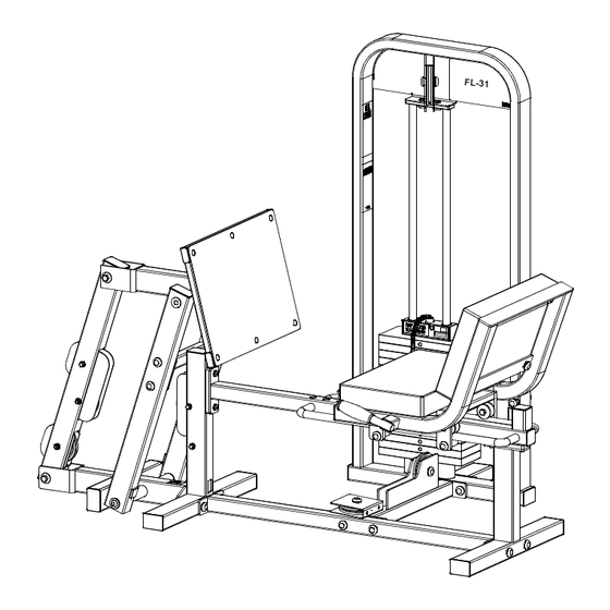
- Page 1 ELECT ITNESS IRCUIT SF-300 LEG PRESS ASSEMBLY MANUAL AM-SF-0300 Rev 11/02...
- Page 2 AFETY 1. Review and understand all of the warning labels affixed to the machines and the facility safety sign. Replace any warning label at first sign of wear. Labels and the Facility Safety Sign may be obtained from Paramount free of charge. 2.
-
Page 3: Maintenance
MAINTENANCE 1. Frames: Wipe all machines down with a damp cloth and dry completely each day. This includes painted, chrome parts and upholstered pads. 2. Painted/chrome parts: Use Simple Green or similar cleaner for light dirt and grime. Use TurtleWax® Polishing Compound or a good car polish to remove heavier dirt and grease as well as for polishing. -
Page 4: Tools Required
TOOLS REQUIRED: WRENCH 7/16” (11mm) ALLEN WRENCH SOCKET 9/16” (14mm) 5/32” (4mm) 3/4” (19mm) 7/16” (11mm) RUBBER SOCKET 7/32” (6mm) 7/8” (22mm) 9/16” (14mm) MALLET WRENCH 5/16” (8mm) 3/4” (19mm) 15/16” (24mm) SF-0300CTN1: 8093040 9099780X STABILIZER FOOT SELECTOR BAR 9000801X (2) GUIDE RODS LP-4518 0301580X... - Page 5 SF-0300CTN2: 0301520 0301550X ADJ. TUBE SEAT TROLLEY ASSY. ASSY. 0301575X LP-4552X REAR BRACE PRESS ASSY. ASSY. 0301535X 0301570 PULLEY BRACE PIVOT BASE ASSY. ASSY.
- Page 6 HW-0300-2: B 582 (2) B 900 (6) B1182 (4) B 924 (2) B 447 B 898 D1017 LP-4563 (2) B 921 (13) B 682 (4) 0301597 (4) B 460 B1136 (2) HW-0301-1: 3/8-16 x 1 1/4 HHCS 3/8-16 x 3/4 BHCS 3/8 Split washer 3/8-16 x 1 BHCS 3/8 Lock Washer...
- Page 7 MINIMUM FLOOR AREA REQUIRED: 44” 80” (203 cm) (112 cm) IN USE HEIGHT= 60” (152 cm) MACHINE WEIGHT (NOT INCLUDING 73” (185 cm) WEIGHT OF USER): W/ 170LB* STACK 537 LB 109” (277 cm) W/ 250LB** STACK 617 LB IN USE SHROUD OPTION +30 LB * Actual resistance 300lb ** Actual resistance 375lb...
- Page 8 TOP VIEW Pulley Housing 0301510X 0301575X NOTE: STABILIZER FOOT MUST BE 8093040 ATTACHED TO THE MACHINE! 0301525X 0301570 H (2) G (2) D (2) 0301530 H (2) 0301535 NOTE: WHEN INSTALLING HARDWARE, TIGHTEN BY HAND ONLY UNTIL ALL COMPONENTS ARE ASSEMBLED. BOLT HEADS SHOULD FACE TO OUTSIDE OF MACHINE WHERE POSSIBLE.
- Page 9 G (2) E (2) 0301520 0301515 E (2) E (2) D1017 CENTERED ON TUBE TO CONTACT 0301570 LP-4527 (NOTE ORIENTATION) FACES MUST BE PARALLEL AT REST 0301540X STOP BLOCK ON THIS SIDE C 930 C 755 LP-4562...
- Page 10 LP-4552X LP-4563 C 476 C 755 C 766 LP-4552X NOTE: THIS END ANGLED C 476 C 755 C 766 LP-4563...
- Page 11 LP-4562 C 930 C 755 C 930 C 755 D (2) 0301540X C 930 C 755...
- Page 12 C 660 C 754B C 955A C 766A C 955 (6 EA) LP-4518 0301550X USE THIS HARDWARE TO INSTALL 0301597’S 3/8-16 x 1 1/4 SHCS 3/8 lock washer 3/8 washer 0301597 (4)
-
Page 13: Weight Stack Installation
0301590X 0301580X A (4) T (4) WEIGHT STACK INSTALLATION Review the equipment order to deter- P/N: B1602 mine the weight stack configuration. Comprised of The boxes are marked with the quan- (4) EACH 10lb MACHINED WEIGHT PLATES tity and weight of the plates. P/N: B1603 Comprised of (4) EACH 15lb MACHINED WEIGHT PLATES... - Page 14 Front View 9000801X B (2) B 447 9099780X NOTE: 2 WEIGHTS MUST BE C 461 SECURED C 754B WEIGHT C 955A (2) PLATES C 766A C 955 (2) C 757 (2) B 582 (2) NOTE: MOVE CAP PLATE 9099780X UP TO PULLEY HOUS- NOTE: IF INSTALLING THE WEIGHT SHROUD ING TO SET THE CORRECT GUIDE ROD AND BRACKET OPTION REFER TO THE INSTALLATION...
- Page 15 MAKE SURE B 898 LOCKING NUT MAX! IS SECURE! 1 3/8” (35mm) 0301600 R (4 PULLEYS) 0301585 (2) C 451 C 749 B 900 (6) C 766A Front View 0301600 B 460 NOTE: PARAMOUNT SELECTOR PIN B 460 IS THE ONLY PIN THAT SHOULD BE USED WITH THIS MACHINE.
- Page 16 ELECT ITNESS WEIGHT STACK LABELS EIGHT TACK ABEL NSTALLATION Hardware Bag 1901-3 is packed with a weight stack number label set. Follow the instructions printed on the label. Below is a list of weight stacks and the corresponding label set part numbers: Wt.
-
Page 17: Warning Labels
WARNING LABELS The following warning labels are affixed to the SF-0300. Be certain that you and the facility staff are aware of the meaning and importance of each label. If the labels become damaged, replacements can be ordered free of charge from Paramount. MAINTENANCE WARNING WARNING... -
Page 18: Day Warranty
Contact Paramount Fit- ness Corp., 6450 E. Bandini Blvd., Los Angeles, California 90040-3185, before returning any defective equipment. Paramount Fitness Corp. © 1999. Paramount Fitness Corp. © 1993, 1995, 1997...
Need help?
Do you have a question about the SF-300 and is the answer not in the manual?
Questions and answers