Table of Contents
Advertisement
Advertisement
Table of Contents

Related Manuals for Paramount Fitness FS-50


Summary of Contents for Paramount Fitness FS-50
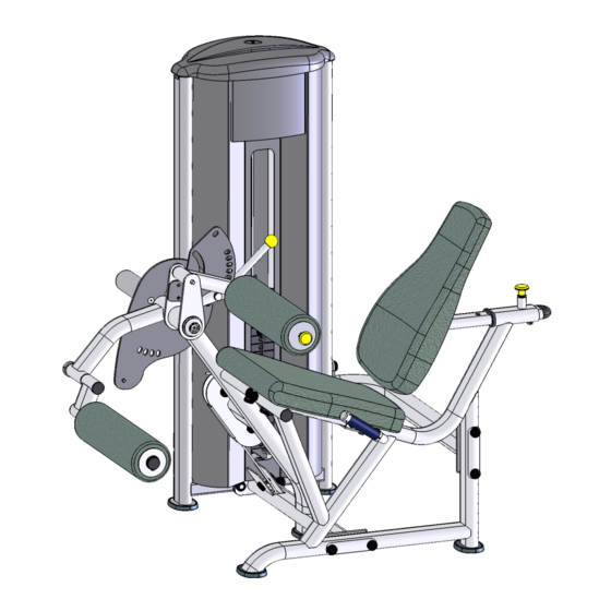
- Page 1 FS-50 XTENSION SSEMBLY ANUAL AM-FS50...
- Page 2 ESSAGE TO USTOMERS Thank you for purchasing the Paramount FS-50 Leg Extension/Curl machine. Because of the many unique features included in this product, this manual was created to provide you with information on how to properly assemble and maintain your equipment. Proper maintenance will ensure that your new equipment will last for years.
-
Page 3: Table Of Contents
ABLE ONTENTS ........................4 AFETY ................5 ENERAL ARE AND AINTENANCE .................... 6 IMENSIONS AND EIGHT ......................7 REPARATION FS-50 B ................. 8 ARTON ONTENTS FS-50 B ................. 9 ARTON ONTENTS & A NSTALLATION SSEMBLY 1: A ........... 10 SSEMBLE THE... -
Page 4: Safety
AFETY 1. Review and understand all of the warning labels affixed to this machine and on the facility safety sign. Replace any warning label at first sign of wear. Labels and the Facility Safety Sign may be obtained from Paramount free of charge. 2. -
Page 5: Eneral Are And Dimensions And Weight
ENERAL ARE AND AINTENANCE 1. Cable Ends: Inspect end fittings daily for wear. Replace cables at the first sign of wear or on an annual basis. If the cable tension has been adjusted, be certain that the cable nut is tight. 2. - Page 6 IMENSIONS AND EIGHT “I ” M ACHINE IMENSIONS 43.0” (109 cm) Maximum user weight: 300 lbs. (136 KG) ACHINE EIGHT AND LOOR OADING EIGHT TACK ONFIGURATION ACHINE WEIGHT PPROXIMATE LOOR OADING 170 lbs. 457 LBS [207 KG] 72 LBS/FT [351 KG/M 250 lbs.
-
Page 7: Preparation
REPARATION EQUIRED OOLS Ratchet Wrench and Sockets: 9/16” Wrenches: 9/16”, 3/4”. (or an adjustable crescent wrench). Rubber Mallet Allen wrenches: (included with the machine) Hardware Measurement Guide: BHCS - BUTTON HEAD CAP SCREW SHCS - SOCKET HEAD CAP SCREW FHCS - FLAT HEAD CAP SCREW HHCS - HEX HEAD CAP SCREW MEASURE BOLT FROM HERE... -
Page 8: Box 1 Cartonc
FS-50 B ARTON ONTENTS QTY. ESCRIPTION FS-CAP-000X TOP UPRIGHT CAP FS-GRD-100X GUIDE ROD FS-SHD-150X REAR SHROUD FS50-SHD-100X FRONT SHROUD FS50-UPR-000X UPRIGHT FRAME FS-BKT-000 GUIDE ROD BRACKET FS-WSB-000 WEIGHT STACK BASE FS-PAD-000X BACK PAD... -
Page 9: Box 2 Cartonc
FS-50 B ARTON ONTENTS QTY. ESCRIPTION FS50-MFR-000X MAIN FRAME FS50-ARM-000X EXT/CURL ARM FS50-ARM-100X THIGH PAD, ASSY FS50-ARM-200X ANKLE ROLLER PAD, ASSY FS50-MFR-300X HANDLES FS50-ADJ-000X THIGH ADJUSTMENT PLATE FS50-MFR-100X FRONT FRAME FS50-MFR-400X AXLE HOUSING FS50-MFR-200X REAR BRACE FS50-AXL-000X AXLE AND HUB... -
Page 10: Frame Components
5. After aligning all component edges and C 955A BASE, PLASTIC CAP surfaces, tighten ALL the hardware. FS50-MFR-000X MAIN FRAME FS50-MFR-100X FRONT FRAME FS50-MFR-200X REAR BRACE FS50-UPR-000X UPRIGHT FRAME S-550 RUBBER FOOT FS-CBL-100X FS-50 CABLE Assemble the cable (FS50-CBL-100X) as shown. - Page 11 1: A SSEMBLE THE RAME OMPONENTS 7, 1, 4, 8, 5 7, 2, 4, 8, 5 DETAIL D 7, 3, 8, 5 7, 1, 4, 8, 5 DETAIL E 7, 3, 8, 5 DETAIL C 7, 6, 8, 5 DETAIL B 7, 6, 8, 5 DETAIL A...
-
Page 12: Pads And Handles
2: A SSEMBLE THE ADS AND ANDLES QTY. ESCRIPTION 1. Assemble the back pad to the seat C 445 SCREW, 3/8”-16 X 1” frame. C 451 SCREW, 3/8”-16 X 2-3/4” 2. Loosely assemble the handles to C 455 SCREW, 3/8”-16 X 4” the main frame. -
Page 13: Arm And Axle
3: A SSEMBLE THE RM AND 1. Assemble the adjustment disc to the axle QTY. ESCRIPTION with (4) Flat Head screws. Use blue C 445 SCREW, 3/8”-16 X 1” HHCS Loctite #242 on the threads of the C 653A SCREW, 3/8”-16 X 3/4” FHCS screws. -
Page 14: Step 1: Assemble The Step 2: Assemble The
4: A SSEMBLE THE OLLERS 1. Assemble the ankle roller pad as QTY. ESCRIPTION shown. Assemble the collar so that FS50-AXL-102X SCREW, 1/2”-13 X 5-1/4” FHCS the pad frame can rotate freely. C-658 SCREW, 3/8”-16 X 1” FHCS C-754C FLAT WASHER, 3/8” 2. -
Page 15: Cable And Pulleys
ULLEYS 1. Route the cable as shown, installing QTY. ESCRIPTION the associated pulleys and hardware FS50-CBL-100X FS-50 CABLE as you go along. B 900 PULLEY, 4-1/2” DIA. C 448 SCREW, 3/8” X 1-3/4” HHCS 2. After assembly, make sure the cable C 766A LOCKNUT, 3/8”-16... -
Page 16: Weight Stack
6: A SSEMBLE THE EIGHT TACK ESCRIPTION 1. Place the guide rods in the upright. C 445 SCREW, 3/8”-16 X 1” HHCS 2. Install the weight stack base, rubber C 749 LOCKWASHER 3/8” bumpers, and washers. C 754C FLAT WASHER, 3/8” FS-GRD-100X ASSY, GUIDE ROD 3. -
Page 17: Ront Shroud
7: I NSTALL THE RONT HROUD QTY. ESCRIPTION 1. Place the front shroud into position. C 445 SCREW, 3/8”-16 X 1” HHCS 2. Align the holes and assemble the C 749 LOCK WASHER hardware. C 754C FLAT WASHER FS50-SHD-100X FRONT SHROUD 3. -
Page 18: Step 7: Install Thef
8: I NSTALL THE HROUD AND 1. Set the lower screws of the shroud into the QTY. ESCRIPTION lower brackets on the upright frame. C 766A LOCKNUT, 3/8”-16 C 675D SCREW, 1/4”-20 X 1/2” BHCS 2. Then align the holes for the brackets at C 444 SCREW, 3/8”-16 X 3/4”... -
Page 19: Weight Stack Label
9: I NSTALL THE EIGHT TACK ABEL 1. Select the appropriate weight stack label(s) according to your order. You can install pound labels, kilogram labels, or both. 2. If you ordered a 170 lb. weight stack, use labels: LBL-WSE-01170 (for pounds) LBL-WSM-01170 (for kilograms). -
Page 20: Machine Labels
ACHINE ABELS The following are the Warning labels required for this FS machine. If any of these labels are missing or become damaged, Paramount will replace them free of charge. Note: these labels are not to scale. WARNING WARNING SERIOUS INJURY CAN OCCUR MAXIMUM ON THIS EQUIPMENT IF THE Height Under Nut... -
Page 21: Service
Service representative at 1-800-721-2121 or 1-213-721-2121. Or by E-mail at nasales@paramountfitness.com. Before you call, please have the following information ready. • Model Number: FS-50 LEG EXT/CURL • Serial Number: ________________________ • Date of Installation: ____________________ • A brief description of the problem The serial number is located on the front of the upright frame at the bottom as shown. -
Page 22: Arranty
Paramount. This limited warranty gives you specific legal rights, and you may also have other rights which may vary from state to state. Contact Paramount Fitness Corp., 6450 E. Bandini Blvd., Los Angeles, California 90040-3185, for a list of authorized dealers or before returning any defective equipment. - Page 23 NOTES...
- Page 24 Paramount Fitness Corporation 6450 E. Bandini Blvd. Los Angeles, CA 90040-3185 Phone: 1-323-721-2121 Fax: 323-724-2000 1-800-721-2121 www.paramountfitness.com AM-FS50-030907.fm REV:3/9/07...
Need help?
Do you have a question about the FS-50 and is the answer not in the manual?
Questions and answers