
Related Manuals for AZZA P4M2-BV


Summary of Contents for AZZA P4M2-BV
- Page 1 AZZA P4M Mainboard Series Cover Click Here Table Of Contents Click Here Introduction Click Here Hardware Installation Click Here BIOS Management Click Here...
- Page 2 Series Manual Series Manual SOCKET 478 DDR M-ATX Mainboard P4M2 P4M2- - - - BV P4M2 P4M2 P4M2 P4M2 P4M2 P4M2- - - - BL Version 1.x UM-P4M2-ABVL-E1 Rev 1.0V Creation Date: 25 January 2002 AZZA P4M Mainboard Series Page 1...
-
Page 3: User Notice
If any of these items are damaged or missing, please contact your dealer or sales representative for assistance. Technical Support If you require additional information or assistance during installation please contact your dealer. Your dealer will be able to provide the latest information. Page 2 AZZA P4M Mainboard Series... -
Page 4: Table Of Contents
2.6.2. SL LED Connector .................. 20 2.6.3. IDE HDD LED Connector ................. 20 2.6.4. Reset Button Connector ................21 2.7. Speaker and Power LED Connector ............21 2.7.1. Speaker Connector ................. 21 2.7.2. Front Panel Power LED ................21 AZZA P4M Mainboard Series Page 3... - Page 5 3.13.1. Save & Exit Setup ................46 3.13.2. Exit Without Saving ................46 Appendix A:- Optional Items Page 47 A.1. Standard Infrared Connector ..............47 A.2. Wake On LAN Connector ................. 47 A.3. S/PDIF Connector ................... 48 Page 4 AZZA P4M Mainboard Series...
-
Page 6: Chapter 1:- Introduction
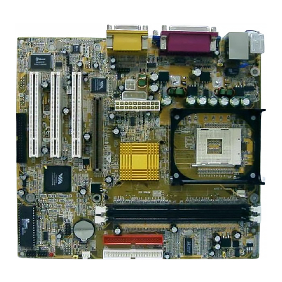
PWR-LED CN17: CHASSIS FAN CN10: IDE2 JP4: Clear CMOS System Panel and Power LED The IR, WOL and S/PDIF CN31: USB4 Connectors connectors both CN30: USB3 manufacturing options. See appendix A for de- tails AZZA P4M Mainboard Series Page 5... -
Page 7: Overview
Onboard VGA (Onchip PRO Savage DDR). Each P4M mainboard has and 2 fan connectors as well as CD-IN and AUX-IN connectors. 1.2.2. The P4M Mainboard Models There are two models in this series: The P4M2-BV and the P4M2-BL. The P4M2-BL comes with Onboard LAN (RealtekRTL8100B). 1.2.3. Mainboard Dimensions These boards are Micro—ATX form factors. - Page 8 These mainboards are equipped with three dedicated PCI slots and one AMR slot. Onboard Audio Features Supports Microsoft DirectSound/ DirectSound 3D and AC97 Full Duplex. Onboard LAN Features (Optional for P4M2-BV) The P4M2-BL models come with onboard LAN which support Real- tekRTL8100B. Word Size...
- Page 9 One SPP/ECP/EPP DB-25 parallel port. One mini-DIN-6 PS/2 mouse port. One mini-DIN-6 PS/2 keyboard port. One game/MIDI port. On LAN Port (RJ-45) connector (only for the P4M2-BL) Three audio jacks: speak-out, line-in and mic-in. Page 8 AZZA P4M Mainboard Series...
-
Page 10: System Health Monitor Functions
If the values are over or under the set range a warning message will automatically pop up. We recommend that you use the Default Settings, which are the ideal settings that will maintain the system in a good working condition. AZZA P4M Mainboard Series Page 9... -
Page 11: Installation
ACPI Ready The mainboard is designed to meet the ACPI (Advanced Configuration and Power Interface) specification. ACPI has energy saving features that support OS Direct Power Management (OSPM) for round the clock PC operation. Page 10 AZZA P4M Mainboard Series... -
Page 12: Chapter 2:- Hardware Installation
Front Audio Connector CN45 Auxiliary In Aux-IN External Connectors PS/2 Keyboard Connector PS/2 KB PS/2 Mouse Connector PS/2 MS Serial Port 1 COM1 (optional ): These are manufacturing options. Please see Appedix A for more details. AZZA P4M Mainboard Series Page 11... -
Page 13: Installation Steps
Before you start installing your mainboard we strongly recommend that you use a grounded anti-static mat. We further recommend that you attach an anti-static wristband, which is grounded at the same location as the mat, to your wrist. Page 12 AZZA P4M Mainboard Series... -
Page 14: Expansion Slots, Jumpers And Internal Connectors
Hardware Installation 2.3. Expansion Slots, Jumpers and Internal Connectors AZZA P4M Mainboard Series Page 13... -
Page 15: Cpu, Memory And Expansion Slots
Important: The DIMM’s can only be fitted into the slots in one orien- tation. Make sure that the DIMM’s are in the correct orientation and the pins are correctly aligned before you insert them. Page 14 AZZA P4M Mainboard Series... -
Page 16: Pci Slots
When you are inserting your PCI card make sure that the pins are correctly aligned. When the pins 11 Pins properly aligned with hole’s in the slot, push down gen- tly. AZZA P4M Mainboard Series Page 15... -
Page 17: Amr (Audio Modem Riser) Slot
BIOS setup. Please refer to your hard drive manual for the appropriate jumper settings. Primary and Secondary IDE Connectors IDE1 Pin 1 IDE2 Pin 1 Page 16 AZZA P4M Mainboard Series... -
Page 18: Cpu And Chassis Fan Connectors
Pin 16 Pin 1 +12VDC Pin 7 Pin 17 Pin 2 Pin 8 PWR_OK Pin 18 -5VDC Pin 3 Pin 9 +5VSB Pin 19 +5VDC Pin 4 +5VDC Pin 10 +12VDC Pin 20 +5VDC AZZA P4M Mainboard Series Page 17... -
Page 19: Cd Audio In And Auxiliary-In Connectors
USB ports available. The P4M2 mainboards has two internal USB connectors (CN30 and CN31). This enables you to use an extra two USB devices. Cable for these additional connectors needs to be purchased separately. Page 18 AZZA P4M Mainboard Series... -
Page 20: Front Audio Connector
Pin 2 Power On/OFF and Suspend Switch +5V DC Pull Up Ground Connector Standby LED Connector Standby DC Pull Ground HDD LED Connector +5V DC Pull Up Ground Reset Button Connector Reset Control Ground AZZA P4M Mainboard Series Page 19... -
Page 21: Pw: Power On/Off And External Suspend Switch Connector
+5V and the SL LED will be on. If this LED is off it means that the AC power is “OFF” or has been disconnected. 2.6.3. IDE HDD LED Connector Any read and write activity by the HDD will turn this LED on. Page 20 AZZA P4M Mainboard Series... -
Page 22: Reset Button Connector
2.8.2. PS/2 Mouse Connector. Connector: CN 2 Type: 6 pin female This connector only supports a PS/2 mouse plug. If a PS/2 mouse is de- tected then IRQ 12 will be directed to CN 2. AZZA P4M Mainboard Series Page 21... -
Page 23: Serial Port 1 (Com 1) Connector
(The USB cable is not included USB 1 with the mainboard). 2.8.6. VGA Connector Connector: CN 19 Type: 15 pin female. Connect your VGA monitor adapter to this connector. Page 22 AZZA P4M Mainboard Series... -
Page 24: Audio/Game Port Connector
“SHORT.” Below is an example of a short set- ting on a jumper. The jumper settings and locations are shown on page 24. Two Pin Jump- Three Pin Jumpers PIN: 1 PIN: 1 Open Short SHORT PIN 1/PIN 2 PIN2/PIN 3 AZZA P4M Mainboard Series Page 23... -
Page 25: Jp1: Keyboard Power
Insert the jumper cap on Pin 2 and Pin 3 for 3 ~ 5 seconds. Pull out the jumper cap and replace it on Pin 1 and Pin 2. Turn your PC on and run the BIOS setup program Page 24 AZZA P4M Mainboard Series... -
Page 26: Chapter 3:- Managing The Pc Bios
F10 : Save and Exit Setup Time, Date, Hard Disk Type ... Note! BIOS software is continuously updated therefore the BIOS menus and the descriptions that are given in this manual are for reference purposes only. AZZA P4M Mainboard Series Page 25... -
Page 27: Standard Cmos Setup
Hard Drive parameters. Move the selection bar to the IDE Hard Drive you want to configure. Press the "ENTER" key. If you select “AUTO” the system BIOS will detect the HDD type automatically. Page 26 AZZA P4M Mainboard Series... - Page 28 3-1/2 inch double-sided drive 2.88 MB Video This field selects the type of primary video subsystem that is on your com- puter. The BIOS CMOS Setup Utility will automatically detect the correct video type. AZZA P4M Mainboard Series Page 27...
-
Page 29: Advanced Bios Features
BIOS will show a warning message on Security Option [Setup] OS Select For DRAM > 64 MB [Non-OS2] screen and alarm beep. HDD S.M.A.R.T Capability [Disabled] Video BIOS Shadow [Enabled] Small Logo (EPA) Show [Enabled] Page 28 AZZA P4M Mainboard Series... - Page 30 720 KB, 1.2 MB, and 1.44 MB capacity all have 80 tracks. Very few modern PCs have 40-track floppy drives so we therefore recommend that you set this field to Disabled to save time. AZZA P4M Mainboard Series Page 29...
- Page 31 These fields allow you to change the Video BIOS location from ROM to RAM. Information access is faster through RAM than ROM. Therefore when you enable this option you will enhance your system performance. Page 30 AZZA P4M Mainboard Series...
-
Page 32: Advanced Chipset Features
By SPD :The BIOS will automatically detect the actual DRAM Clock. 100 MHz :The DRAM clock speed will be PC1600 (100 MHz DDR). 133 MHz :The DRAM clock speed will be PC2100 (133 MHz DDR). AZZA P4M Mainboard Series Page 31... - Page 33 This item allows you to adjust the AGP driving force. !AGP Master 1 WS Write When Enabled, writes to the AGP are executed with one-wait states. !AGP Master 1 WS Read When Enabled, reads to the AGP are executed with one-wait states. Page 32 AZZA P4M Mainboard Series...
- Page 34 The options are: 4 min, 8 min, 16 min and 32 min. VGA Share Memory Size This field enables you to select the amount of system memory you wish to allo- cate for video memory. AZZA P4M Mainboard Series Page 33...
-
Page 35: Integrated Peripherals
The chipset contains a PCI IDE interface with support for two IDE channels. To activate the primary IDE interface select Enabled. If you want to disable the onboard IDE 1 and/or 2, then select Disabled. Page 34 AZZA P4M Mainboard Series... - Page 36 Disabled in this field. !Onboard Serial Port 1/2 These two selection fields allow you to select the I/O address and corre- sponding interrupts for the first and second serial port. AZZA P4M Mainboard Series Page 35...
- Page 37 This item allows you to determine the I/O address and the IRQ for the on- board parallel port. The default settings are adequate and should not give you any problems. If they do you can try to change them. Page 36 AZZA P4M Mainboard Series...
- Page 38 Onboard LAN Boot ROM This field can be used to enable or disable the Boot ROM of the onboard Real- tek 10/100 Adapter LAN Chip to support the boot up of a diskless client func- tionality unit. AZZA P4M Mainboard Series Page 37...
-
Page 39: Power Management Setup
When enabled, after the set time of system inactivity, all devices except the CPU will be shut off. Video Off Option When enabled, this feature allows the VGA adapter to operate in a power saving mode. Page 38 AZZA P4M Mainboard Series... - Page 40 AC power failure occurred, it will remain off when the power returns. If the system’s power is on when the AC power failure occurred, the system will power-on when the power returns. AZZA P4M Mainboard Series Page 39...
-
Page 41: Irqs Activity Monitoring
RTC (real-time clock) alarm awakens the system from Suspend mode. !IRQs Activity Monitoring The following is a list of IRQ’s, Interrupt ReQuests, which can be exempted much as the COM ports and LPT ports above can. When an I/O device Page 40 AZZA P4M Mainboard Series... -
Page 42: Pnp/Pci Configuration
Normally, you leave this field Disabled. If you have installed a new add-on and the system reconfiguration has caused such a serious conflict that the op- erating system cannot boot then select Enabled. Selecting Enabled will reset AZZA P4M Mainboard Series Page 41... -
Page 43: Pc Health Status
Current CHASSIS FAN Speed Vcore (V) 1.74 V Vcc3(V) 3.41V + 5 V 4.75 V + 12 V 12.09 V - 12 V -12.11 V VBAT (V) 2.99 V 5VSB (V) 5.26 V Shutdown Temperature [Disabled] Page 42 AZZA P4M Mainboard Series... -
Page 44: Frequency/Voltage Control
DIMM connectors, the clock on the related DIMM and PCI slot will be disabled to reduce the Electro-Magnetic Interference (EMI). Spread Spectrum When Spread Spectrum is enabled, the EMI radiation on this mainboard will be reduced. AZZA P4M Mainboard Series Page 43... -
Page 45: Load Fail-Safe Defaults / Load Optimized Defaults
If the CMOS data is corrupted, or if you selected some CMOS settings and find that the PC system becomes very unstable, you should try to load the opti- mized default values first and then re-configure the BIOS. Page 44 AZZA P4M Mainboard Series... -
Page 46: Set Supervisor Password And User Password
BIOS settings, but you cannot change them. The only set- ting you can change is the "User Password" and you can also select "SAVE & EXIT SETUP" and "EXIT WITHOUT SAVING" from the main menu. (If you use AZZA P4M Mainboard Series Page 45... -
Page 47: Save & Exit Setup/Exit Without Saving
CMOS RAM. If you do not want to save any of the changes, or settings you selected in the BIOS SETUP utility, move the selection bar to the “EXIT WITHOUT SAVING” option. Press the “Enter” key. Then press “Y” Page 46 AZZA P4M Mainboard Series... -
Page 48: Appendix A: Optional Items
WOL LAN card or the modem to trigger the power on the PC system, the switching power supply must have the ability to provide a driving current of at least 720 mA and be connected to a “5V standby” voltage. AZZA P4M Mainboard Series Page 47... -
Page 49: S/Pdif Connector
The Sony Phillips Digital Interface, S/PDIF, connector is a digital interface that can be used to improve the quality of the sound output from your system. Top View of the S/PDIF +5VDC S/PDIF data input signal Ground Page 48 AZZA P4M Mainboard Series...
Need help?
Do you have a question about the P4M2-BV and is the answer not in the manual?
Questions and answers