
Related Manuals for AZZA P4X2 Series


Summary of Contents for AZZA P4X2 Series
- Page 1 AZZA P4X2 Mainboard Series Cover Click Here Table Of Contents Click Here Introduction Click Here Hardware Installation Click Here BIOS Management Click Here...
- Page 2 P4X2- - - - AS P4X2 P4X2 P4X2 P4X2- - - - AV P4X2 P4X2 P4X2 P4X2 P4X2- - - - AC P4X2 P4X2 Version 1.x UM-P4X2-ACVSD-E1 Rev 1.0V Creation Date: 22 August 2001 AZZA P4X2-A MAINBOARD SERIES Page 1...
- Page 3 If any of these items are damaged or missing, please contact your dealer or sales representative for assistance. Technical Support Technical Support Technical Support If you require additional information or assistance during installation please con- will be able to provide the latest information. tact your dealer. Your dealer Page 2 AZZA P4X2-A MAINBOARD SERIES...
-
Page 4: Table Of Contents
2.5. System Panel Buttons and LED Connectors ..........20 2.5.1. PW: Power On/Off and External Suspend Switch Connector ....... 21 2.5.2 Standby LED Connector ................22 2.5.3. IDE HDD LED Connector ................ 22 2.5.4. Reset Button Connector ................22 AZZA P4X2-A MAINBOARD SERIES Page 3... - Page 5 PC Health Status ..................43 3.10. Frequency/Voltage Control ..............44 3.11. Load Optimized Defaults ................ 45 3.12. Set Supervisor Password ................ 46 3.13. Set User Password .................. 47 3.14. SAVE & EXIT SETUP/EXIT WITHOUT SAVING ........48 Page 4 AZZA P4X2-A MAINBOARD SERIES...
-
Page 6: Chapter 1:- Introduction
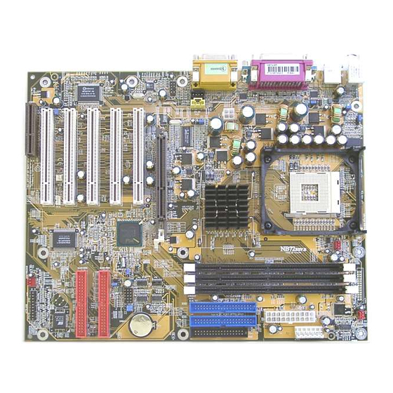
Introduction Chapter 1 Chapter 1 Introduction Introduction Chapter 1 Introduction 1.1. MAINBOARD LAYOUT AZZA P4X2-A MAINBOARD SERIES Page 5... -
Page 7: Mainboard Series
Equipped with a switching voltage regulator that automatically detects +1.10V to +1.85V DC power supply. System Memory • 3.0GB DRAMs for registered DDR SDRAM modules. • 1.5GB DRAMs for unbuffered DDR SDRAM modules. • Three 184-pin DIMM sockets. • Supports PC1600 and PC2100 DDR SDRAM. Page 6 AZZA P4X2-A MAINBOARD SERIES... - Page 8 USB 3, USB 4, USB 5 and USB 6 are internal connectors that can be used to connect other USB devices. (Optional cable for four connectors is sold separately). Connectors • One connector for IrDA interface (Optional for P4X2-AS, P4X2-AV and P4X2- AZZA P4X2-A MAINBOARD SERIES Page 7...
- Page 9 If a device is incorrectly installed, not installed or damaged a voice announcement will be made. Devices which are supported by this alarm are: CPU, Memory, Video Card, FDD, HDD, Keyboard and Battery. Page 8 AZZA P4X2-A MAINBOARD SERIES...
-
Page 10: System Health Monitor Functions
CPU and chassis fans. You are allowed to manually set a range to the items being monitored. If the values are over or under the set AZZA P4X2-A MAINBOARD SERIES Page 9... -
Page 11: Installation
ACPI Ready The mainboard is designed to meet the ACPI (Advanced Configuration and Power Interface) specification. ACPI has energy saving features that support OS Direct Power Management (OSPM) for round the clock PC operation. Page 10 AZZA P4X2-A MAINBOARD SERIES... -
Page 12: Chapter 2:- Hardware Installation
Front Audio Connector Front Audio CN41 Smart Card Reader CN42 System Management Bus External Connectors PS/2 Keyboard Connector PS/2 KB PS/2 Mouse Connector PS/2 MS Serial Port 1 COM1 Serial Port 2 COM2 Parallel Port AZZA P4X2-A MAINBOARD SERIES Page 11... -
Page 13: Installation Steps
We further recommend that you attach an anti-static wrist- band, which is grounded at the same location as the mat, to your wrist. Only use an ATX 12V Power Supply. Page 12 AZZA P4X2-A MAINBOARD SERIES... - Page 14 Hardware Installation Expansion Cards, Connectors and Jumpers For The P4X2 Series AZZA P4X2-A MAINBOARD SERIES Page 13...
-
Page 15: Cpu, Memory And Expansion Slots
45°. Make sure that the DIMM is in the correct orientation. Place the DIMM on the slot and push down firmly.The white levers will come back up and lock the module in place. Top View of a 184-pin DIMM Slot 40 pins 52 pins Page 14 AZZA P4X2-A MAINBOARD SERIES... -
Page 16: Pci Slots
MB/s. This allows 3D applications to run more smoothly. The P4X2-A mainboards each come with one AGP slot. This slot is able to support 1x, 2x and 4x AGP cards. Top View of an AGP Slot 66 pins AZZA P4X2-A MAINBOARD SERIES Page 15... -
Page 17: Cnr (Communications Network Riser) Slot
IDE devices each. If you install two hard drives, you need to configure the second drive to slave mode in the BIOS setup . Please refer to your hard drive manual for the appropriate jumper settings Top View of an IDE Connector PIN 1 20 PINS Page 16 AZZA P4X2-A MAINBOARD SERIES... -
Page 18: Standard Infrared Connector
+3.3V and +5V power supply. These increased power supplies are necessary to provide ex- tra power for the slot. The ATX 12V power supplies are all downward compatible with stan- dard ATX power supplies. AZZA P4X2-A MAINBOARD SERIES Page 17... -
Page 19: Atx Power Supply Connectors
720 mA and be connected to a “5V standby” voltage. Top View of a WOL/WOM Connec- Front View of a WOL/WOM Con- nector Ground 5V_SB Ground WOL/WOM 5V_SB WOL/WOM Page 18 AZZA P4X2-A MAINBOARD SERIES... -
Page 20: Wol (Wake-On-Lan) And Wom (Wake-On-Modem) Connectors
The mainboard comes with an internal S/PDIF connector. S/PDIF is a digital interface that can be used to improve the quality of the sound output from your system. The diagram is on the following page. AZZA P4X2-A MAINBOARD SERIES Page 19... -
Page 21: Front Audio Connector
PIN 8: No Con- PIN 9: SCPNST PIN 10: Top View nector SCPNST of the Smart Card Reader Connector PIN 1: +5V DC PIN 2: SCPWR PIN 3: SCC4 PIN 4: SCIO PIN 5: SCCLK Page 20 AZZA P4X2-A MAINBOARD SERIES... -
Page 22: Smb Connector
The system will be turned into Suspend mode (turned into the GREEN mode) When the system is in the Suspend mode:- !"" Press the Power on button (less than 4 seconds), the system will return to Full-ON mode. AZZA P4X2-A MAINBOARD SERIES Page 21... -
Page 23: Standby Led Connector
Ground No Con- connected to the four pin connector. When you nector nector turn your system on, this LED will also be turned POWER LED Top View of the Speaker and Power LED Connector Page 22 AZZA P4X2-A MAINBOARD SERIES... -
Page 24: External Connectors
Two USB ports are available for connecting USB devices. The mainboard is also equipped with an expansion connector that supports four additional USB external connectors. (The USB cable is not included with the mainboard). AZZA P4X2-A MAINBOARD SERIES Page 23... -
Page 25: Audio Game Port Connector
USB power specifications. If you are using such a de- vice it may unstable. If you do experience problems try to change the setting on JP 2. This might help solve this problem. Page 24 AZZA P4X2-A MAINBOARD SERIES... -
Page 26: Jp 4: Cpu Clock
This motherboard has the ability to give voice warning messages during hardware debug- ging. If you leave it open (the default setting) you will receive English messages. If you short the jumper you will receive Chinese messages. AZZA P4X2-A MAINBOARD SERIES Page 25... -
Page 27: Chapter 3:- Managing The Pc Bios
F9 : Menu in BIOS Time, Date, Hard Disk Type ... Note! BIOS software is continuously updated therefore the BIOS menus and the descriptions that are given in this manual are for reference purposes only. Page 26 AZZA P4X2-A MAINBOARD SERIES... -
Page 28: Standard Cmos Setup
This mainboard supports four IDE Hard Drives. These fields allow you to set your Hard Drive parameters. Move the selection bar to the IDE Hard Drive you want to configure. Press the "ENTER" key. If you select “AUTO” the system BIOS will detect the HDD type automatically. AZZA P4X2-A MAINBOARD SERIES Page 27... - Page 29 If you have not installed one of these drives use the default setting. Video This field selects the type of primary video subsystem that is on your computer. The BIOS CMOS Setup Utility will automatically detect the correct video type. Page 28 AZZA P4X2-A MAINBOARD SERIES...
-
Page 30: Advanced Bios Features
This BIOS setting can be used to enable or disable the CPU's L1 (primary) and L2 (secondary) cache. CPU L2 Cache ECC Checking When you select Enabled, the ECC checking will ensure that the data stored on the L2 cache is accurate. AZZA P4X2-A MAINBOARD SERIES Page 29... - Page 31 This field is effective only in systems with two floppy drives. When Enabled is selected physi- cal drive B is assigned to logical drive A, and physical drive A is assigned to logical drive B. Page 30 AZZA P4X2-A MAINBOARD SERIES...
- Page 32 CMOS Real Time Clock (RTC) Ram. For further details on how to do this please see section 2.8.5 on page 25. PS/2 Mouse Function Control If you have installed a serial pointing device and your system has a PS/2 mouse port you should disable this option. AZZA P4X2-A MAINBOARD SERIES Page 31...
-
Page 33: Advanced Chipset Features
[By SPD] X SDRAM Cycle Length X Bank Interleave Disabled X Precharge to Active (Trp) X Active to Precharge (Tras) X Active to CMD (Trcd) X DRAM Burst Len DRAM Command Rate [2T Command] Page 32 AZZA P4X2-A MAINBOARD SERIES... - Page 34 Item Help AGP Mode [2X] Menu Level ! ! ! ! AGP Driving Control [Auto] X AGP Driving Value AGP Fast Write [Disabled] AGP Master 1 WS Write [Disabled] AGP Master 1 WS Read [Disabled] AZZA P4X2-A MAINBOARD SERIES Page 33...
- Page 35 CPU will not have to wait until the write is completed before starting another write cycle. PCI Master 0 WS Write When enabled, writes to the PCI bus are executed with zero wait states. Page 34 AZZA P4X2-A MAINBOARD SERIES...
-
Page 36: Integrated Peripherals
Menu Level ! ! ! ! Primary Master [Auto] Primary Slave [Auto] Secondary MasterPIO [Auto] Secondary Slave PIO [Auto] Primary Master UDMA [Auto] Primary Slave UDMA [Auto] Secondary MasterUDMA [Auto] Secondary Slave UDMA [Auto] AZZA P4X2-A MAINBOARD SERIES Page 35... - Page 37 This chipset can support MC97 Modem. This field allows you to decide whether you want this support or not. If you select “Auto” the BIOS will automatically detect the AC97. If you select “Disabled” the Bios will not detect any support for the AC97 audio/modem. Page 36 AZZA P4X2-A MAINBOARD SERIES...
- Page 38 This field is usually found under the Onboard Serial Port 2 option. If you disable the Onboard Serial Port 2 option then you will probably not be able to configure this field. IR Transmission Delay This field allows you to “Enable” or “Disable” the IR Transmission Delay. AZZA P4X2-A MAINBOARD SERIES Page 37...
- Page 39 This field allows you to select the IRQ for the onboard MIDI port. The default is 10. USB Keyboard Support This field should only be enabled if you are using a USB keyboard. If you are not using this kind of keyboard you should disable it. Page 38 AZZA P4X2-A MAINBOARD SERIES...
-
Page 40: Power Management Setup
This category allows you to select the degree of power saving. The choices are shown be- low. Power Management Min. Saving Minimum power management. Suspend Mode = 1 hr. Max. Saving Maximum power management. Suspend Mode = 1 min. AZZA P4X2-A MAINBOARD SERIES Page 39... - Page 41 PC system, you have to install the “External” modem to your PC system and tell the PC system which serial port connects to the modem by selecting the IRQ in this field, (officially, COM 1 uses IRQ4, and COM 2 uses IRQ3). Page 40 AZZA P4X2-A MAINBOARD SERIES...
- Page 42 An input signal from the modem/LAN will wake up the system from a soft off state. RTC Alarm Resume When enabled, you can use the following two fields to select the time and date to wake up the PC system from power saving mode. AZZA P4X2-A MAINBOARD SERIES Page 41...
-
Page 43: Pnp/Pci Configuration
Select Yes if you are us- [Disabled] PCI/VGA Palette Snoop ing a Plug and Play ca- [Enabled] Assign IRQ For VGA pable operating system. Select No if you need the BIOS to configure non- boot devices. Page 42 AZZA P4X2-A MAINBOARD SERIES... -
Page 44: Pc Health Status
This field allows you to select an operating temperature range for your CPU. If the CPU tem- perature moves out of this range, any warning mechanism you have programmed into your system will be activated. AZZA P4X2-A MAINBOARD SERIES Page 43... -
Page 45: Frequency/Voltage Control
CMOS Setup Utility - Copyright (C) 1984 - 2001 Award Software Frequency/Voltage Control Item Help CPU Vcore Select [Default] Auto Detect DIMM/PCI Clk [Disabled] Menu Level ! ! ! ! Spread Spectrum [Disabled] CPU Clock [100 MHz] CPU Ratio CPU Ratio Page 44 AZZA P4X2-A MAINBOARD SERIES... -
Page 46: Load Optimized Defaults
! ! ! ! PC Health Status ← ← ← ← ↑ ↑ ↑ ↑ ↓ ↓ ↓ ↓ → → → → : Select Item ESC : Quit F10 : Save & Exit Setup Load Optimized Defaults AZZA P4X2-A MAINBOARD SERIES Page 45... -
Page 47: Set Supervisor Password
Whenever you turn on the PC, it will request the user to enter the Password in order to boot up your system. Without the correct password, the PC system will stop and the operating system will not be loaded. Page 46 AZZA P4X2-A MAINBOARD SERIES... -
Page 48: Set User Password
2. When "System" is selected in Security Option: When you turn on your PC, you will be requested to enter the Password. Without the cor- rect password, the PC system will stop and the operation system will not be loaded. AZZA P4X2-A MAINBOARD SERIES Page 47... -
Page 49: Save & Exit Setup/Exit Without Saving
CMOS RAM. If you do not want to save any of the changes, or settings you selected in the BIOS SETUP utility, move the selection bar to the “EXIT WITHOUT SAVING” option. Press the “Enter” key. Then press “Y” Page 48 AZZA P4X2-A MAINBOARD SERIES...
Need help?
Do you have a question about the P4X2 Series and is the answer not in the manual?
Questions and answers