
Related Manuals for AZZA P4X4-ALH


Summary of Contents for AZZA P4X4-ALH
- Page 1 P4X4-ALH Mainboard Manual Socket 478 DDR333 ATX Mainboard Version 1.x UM-P4X4-ALH-E1 Rev 1.0V Creation Date: 02 August 2002 The P4X4-ALH Mainboard Page 1...
- Page 2 If any of these items are damaged or missing, please contact your dealer or sales representative for assistance. Technical Support If you require additional information or assistance during installation please contact your dealer. Your dealer will be able to provide the lat- est information. Page 2 The P4X4-ALH Mainboard...
-
Page 3: Table Of Contents
Chapter 1:- Introduction 1.1. Mainboard and PC 99 ATX External Connector Layout ....... 5 1.2. Overview ....................... 6 1.2.1. The P4X4-ALH Mainboard ..............6 1.2.2. Mainboard Dimensions ................6 1.2.3. Environmental Limitations ..............6 1.3. Features and Specifications ................. 6 1.4. - Page 4 3.12. Set Supervisor Password and User Password .......... 45 3.12.1. Set Supervisor Password ..............45 3.12.2. Set User Password ................45 3.13. Save & Exit Setup/Exit Without Saving ........... 46 3.13.1. Save & Exit Setup ................46 3.13.2. Exit Without Saving ................46 Page 4 The P4X4-ALH Mainboard...
-
Page 5: Chapter 1:- Introduction
PCI 3 PCI 2 PCI 1 Socket CN17: Chassis DIMM1 DIMM2 DIMM3 PWRLED AGP Slot CN30: USB3 CN9: IDE1 CN10: IDE2 CN31: USB4 CN8: FDC CN32: USB5 CN38: USB6 System Panel and Power LED Connectors The P4X4-ALH Mainboard Page 5... -
Page 6: Overview
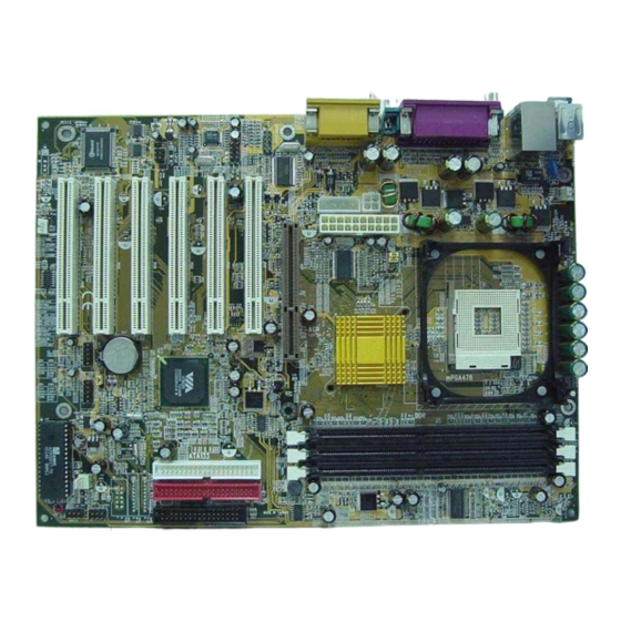
1.2. Overview 1.2.1. The P4X4-ALH Mainboard The P4X4-ALH mainboard is a Pentium™ 4 DDR platform. Onboard it pro- vides three DDR DIMM slots (support up to DDR333), six USB2.0 ports, six PCI slots and one 1.5V 4X/8X AGP slot. There are also two fan connectors (for ad-... - Page 7 DMI pool, which is a part of the system board's Plug and Play BIOS. DMI, along with the appropriately networked software, is designed for easy inventory, maintenance and the simplified troubleshooting of computer systems. The P4X4-ALH Mainboard Page 7...
- Page 8 This mainboard supports ATA 33/66/100/133 hard drives. • PIO Mode 3 and Mode 4 Enhanced IDE (data transfer rate up to 16.6MB/sec.). • Bus mastering reduces CPU utilization during disk transfer. • Supports ATAPI CD-ROM, LS-120 and ZIP. Page 8 The P4X4-ALH Mainboard...
-
Page 9: System Health Monitor Functions
720mA. ACPI Ready The mainboard is designed to meet the ACPI (Advanced Configuration and Power Interface) specification. ACPI has energy saving features that support OS Direct Power Management (OSPM) for round the clock PC operation. The P4X4-ALH Mainboard Page 9... -
Page 10: Chapter 2:- Hardware Installation
Front Audio CN45 Auxiliary In Connector AUX-IN CN46 4 CH OUT 4-Channel Audio Out External Connectors PS/2 Keyboard Connector PS/2 Mouse Connector Serial Port 1 COM1 Serial Port 2 COM2 “Optional”: These are manufacturing options. Page 10 The P4X4-ALH Mainboard... -
Page 11: Installation Steps
Before you start installing your mainboard we strongly recommend that you use a grounded anti-static mat. We further recommend that you attach an anti-static wristband, which is grounded at the same location as the mat, to your wrist. The P4X4-ALH Mainboard Page 11... -
Page 12: Expansion Slots, Jumpers And Internal Connectors
PCI 1 AUX-IN PCI 2 VT8235 PCI 3 CN46: System Panel Buttons and LED Connectors 4 CH OUT PCI 4 CN27: FAN2 CN38:USB6 CN31:USB4 PCI 5 CN32:USB5 CN30:USB3 PWR LED Speaker PCI 6 CN16 WOL Page 12 The P4X4-ALH Mainboard... -
Page 13: Cpu, Memory And Expansion Slots
40 pins Important: The DIMM’s can only be fitted into the slots in one orientation. Make sure that the DIMM’s are in the correct orientation and the pins are cor- rectly aligned before you insert them. The P4X4-ALH Mainboard Page 13... -
Page 14: Pci Slots
533 MB(8x). This allows 3D applications to run more smoothly. The mainboard comes with a 1.5V AGP slot which is able to support 4x/8X AGP cards. Top View of an AGP Slot 21 pins 41 pins Page 14 The P4X4-ALH Mainboard... -
Page 15: Internal Connectors
Please make sure the Pin 1 location. Top View of an IR Connector Front View of an IR Connector Ground IR Receiver IR Transmitter 5V DC No Connection IR Reciever Ground 5V DC IR Transmitter The P4X4-ALH Mainboard Page 15... -
Page 16: Cpu Fan And Chassis Fan Connectors
+5VDC Pin 16 Pin 1 +12VDC Pin 7 Pin 17 Pin 2 Pin 8 PWR_OK Pin 18 -5VDC Pin 3 Pin 9 +5VSB Pin 19 +5VDC Pin 4 +5VDC Pin 10 +12VDC Pin 20 +5VDC Page 16 The P4X4-ALH Mainboard... -
Page 17: Cd-In/Aux-In Connector
2.5.8. S/PDIF Connector (Optional) Connector: CN36 (S/PDIF) Type: 4 pin un-housed The Sony Phillips Digital Interface, S/PDIF, connector is a digital interface that can be used to improve the quality of the sound output from your system. The P4X4-ALH Mainboard Page 17... -
Page 18: Usb3, Usb4, Usb5, Usb6 Connectors
PC. This makes things like plugging in speakers and earphones much less troublesome. Front Audio Connector MIC-IN (Left) Ground MIC-IN (Right) LINE-OUT R LINE-OUT L Page 18 The P4X4-ALH Mainboard... -
Page 19: Ch Out
Rear Left & Rear Right Jack Center & LFE (Woofer) Jack Bracket Rear Left & Rear Right Jack Center & LFE (Woofer) Jack Bracket Speakers connection for 5.1 channel sound systems on P4X4-ALH mainboard. Front Left & Front Right Jack The P4X4-ALH Mainboard Page 19... -
Page 20: System Panel Buttons And Led Connectors
Any read and write activity by the HDD will turn this LED on. 2.6.4. RS: Reset Button Connector If you connect this connector, you will be able to reset you computer by press- ing the reset button at the front of the chassis. Page 20 The P4X4-ALH Mainboard... -
Page 21: Speaker And Power Led Connectors
2.8.3. Serial Port Connectors Connector: CN3 (COM 1)/CN4 (COM2) Type: 9 pin male One serial port is available for a mouse and other serial devices. (I/O addresses used are 3F8H/2F8H/3E8H/2E8H and IRQ3/IRQ4, selected by CMOS setup.) The P4X4-ALH Mainboard Page 21... -
Page 22: Parallel Port Connector
2.8.7. RJ-45 (LAN Port) Connector Connector: CN35 (LAN) The mainboard comes with onboard 10/100 Mb Fast Ethernet Network. The RJ-45 connector allows you to easily connect to a Local Area Net- work (LAN) through a network hub. Page 22 The P4X4-ALH Mainboard... -
Page 23: Jumper Settings
Default: Short If this jumper is short, the mainboard will automatically detect the CPU clock speed FSB 400 MHz or 533MHz. If this jumper is open then the FSB will be forced to be 533 MHz. The P4X4-ALH Mainboard Page 23... -
Page 24: Jp8: Check 1.5V Agp
Insert the jumper cap on Pin 2 and Pin 3 for 3 ~ 5 seconds; Pull out the jumper cap and replace it on Pin 1 and Pin 2; Turn your PC on and run the BIOS setup program. Page 24 The P4X4-ALH Mainboard... -
Page 25: Chapter 3:- Managing The Pc Bios
← ↑ ↓ → : Select Item Esc : Quit Time, Date, Hard Disk Type ... Note! BIOS software is continuously updated therefore the BIOS menus and the descriptions that are given in this manual are for reference purposes only. The P4X4-ALH Mainboard Page 25... -
Page 26: Standard Cmos Setup
This mainboard supports four IDE Hard Drives. These fields allow you to set your Hard Drive parameters. Move the selection bar to the IDE Hard Drive you want to configure. Press the "ENTER" key. If you select “AUTO” the system BIOS will detect the HDD type automatically. Page 26 The P4X4-ALH Mainboard... - Page 27 3.5 in 3-1/2 inch double-sided drive 2.88 MB Video This field selects the type of primary video subsystem that is on your com- puter. The BIOS CMOS Setup Utility will automatically detect the correct video type. The P4X4-ALH Mainboard Page 27...
-
Page 28: Advanced Bios Features
PS/2 Mouse Function Control [Enabled] OS Select For DRAM > 64 MB [Non-OS2] HDD S.M.A.R.T Capability [Disabled] Video BIOS Shadow [Enabled] Full Screen Logo Show [Disabled] Small Logo (EPA) Show [Disabled] Page 28 The P4X4-ALH Mainboard... - Page 29 40 or 80 tracks. Only 360-KB floppy drives have 40 tracks; drives with 720 KB, 1.2 MB, and 1.44 MB capacity all have 80 tracks. Very few modern PCs have 40-track floppy drives so we therefore recommend that you set this field to Disabled to save time. The P4X4-ALH Mainboard Page 29...
- Page 30 Video BIOS Shadow These fields allow you to change the Video BIOS location from ROM to RAM. Information access is faster through RAM than ROM. Therefore when you enable this option you will enhance your system performance. Page 30 The P4X4-ALH Mainboard...
-
Page 31: Advanced Chipset Features
These (six) fields determine the DRAM read/write timing. If you select By SPD then those fields will be automatically configured by the system BIOS. (The performance parameters of the installed memory chips (DRAM) determines the value in those fields.) The P4X4-ALH Mainboard Page 31... - Page 32 This item allows you to adjust the AGP driving force. 4AGP Master 1 WS Write When Enabled, writes to the AGP are executed with one-wait states. 4AGP Master 1 WS Read When Enabled, reads to the AGP are executed with one-wait states. Page 32 The P4X4-ALH Mainboard...
- Page 33 This item allows you to select the delay time before the P4 CPU Thermal Func- tion is enabled. If you are using NT 4.0 you must be active to prevent the sys- tem from hanging. The options are: 4 min, 8 min, 16 min and 32 min. The P4X4-ALH Mainboard Page 33...
-
Page 34: Integrated Peripherals
4IDE Prefetch Mode The onboard IDE drive interfaces supports IDE pre-fetching for faster drive access. If you install a primary and/or secondary add-in IDE interface which does not support pre-fetching set this field to Disabled. Page 34 The P4X4-ALH Mainboard... - Page 35 Disabled in this field. 4Onboard Serial Port 1/2 These two selection fields allow you to select the I/O address and corre- sponding interrupts for the first and second serial port. The P4X4-ALH Mainboard Page 35...
- Page 36 This item allows you to determine the I/O address and the IRQ for the on- board parallel port. The default settings are adequate and should not give you any problems. If they do you can try to change them. Page 36 The P4X4-ALH Mainboard...
- Page 37 Block mode is also known as block transfer, multiple commands, or multiple sector read/write. If your IDE hard drive supports block mode select “Enabled” for automatic detection of the optimal number of block read/writes per sector the drive can support. The P4X4-ALH Mainboard Page 37...
-
Page 38: Power Management Setup
When enabled, after the set time of system inactivity, all devices except the CPU will be shut off. Video Off Option When enabled, this feature allows the VGA adapter to operate in a power saving mode. Page 38 The P4X4-ALH Mainboard... - Page 39 AC power failure occurred, it will remain off Sts: when the power returns. If the system’s power is on when the AC power failure occurred, the system will power-on when the power returns. The P4X4-ALH Mainboard Page 39...
- Page 40 RTC (real-time clock) alarm awakens the system from Suspend mode. 4IRQs Activity Monitoring The following is a list of IRQ’s, Interrupt ReQuests, which can be exempted much as the COM ports and LPT ports above can. When an I/O Page 40 The P4X4-ALH Mainboard...
-
Page 41: Pnp/Pci Configuration
Normally, you leave this field Disabled. If you have installed a new add-on and the system reconfiguration has caused such a serious conflict that the operat- ing system cannot boot then select Enabled. Selecting Enabled will reset the Extended System Configuration Data (ESCD). The P4X4-ALH Mainboard Page 41... -
Page 42: Pc Health Status
Current CHASSIS FAN Speed Vcore (V) 1.74 V + 3.3 (V) 3.41V + 5 V 4.75 V + 12 V 12.09 V - 12 V -12.11 V VBAT (V) 2.99 V 5VSB (V) 5.26 V Shutdown Temperature [Disabled] Page 42 The P4X4-ALH Mainboard... -
Page 43: Frequency/Voltage Control
DIMM connectors, the clock on the related DIMM and PCI slot will be disabled to reduce the Electro-Magnetic Interference (EMI). Spread Spectrum When Spread Spectrum is enabled, the EMI radiation on this mainboard will be reduced. The P4X4-ALH Mainboard Page 43... -
Page 44: Load Fail-Safe Defaults / Load Optimized Defaults
If the CMOS data is corrupted, or if you selected some CMOS settings and find that the PC system becomes very unstable, you should try to load the opti- mized default values first and then re-configure the BIOS. Page 44 The P4X4-ALH Mainboard... -
Page 45: Set Supervisor Password And User Password
BIOS settings, but you cannot change them. The only set- ting you can change is the "User Password" and you can also select "SAVE & EXIT SETUP" and "EXIT WITHOUT SAVING" from the main menu. (If you use The P4X4-ALH Mainboard Page 45... -
Page 46: Save & Exit Setup/Exit Without Saving
CMOS RAM. If you do not want to save any of the changes, or settings you selected in the BIOS SETUP utility, move the selection bar to the “EXIT WITHOUT SAVING” option. Press the “Enter” key. Then press “Y”. Page 46 The P4X4-ALH Mainboard...
Need help?
Do you have a question about the P4X4-ALH and is the answer not in the manual?
Questions and answers