
Related Manuals for AZZA P4X2-AV


Summary of Contents for AZZA P4X2-AV
- Page 1 AZZA P4X Mainboard Series Cover Click Here Table Of Contents Click Here Introduction Click Here Hardware Installation Click Here BIOS Management Click Here...
- Page 2 P4X2 P4X2- - - - AV P4X2 P4X2 P4XA P4XA- - - - AV P4XA P4XA P4XA P4XA P4XA P4XA- - - - BV Version 1.x UM-P4X-2AABV-E1 Rev 1.0V Creation Date: 22 November 2001 AZZA P4X MAINBOARD SERIES Page 1...
- Page 3 If any of these items are damaged or missing, please contact your dealer or sales representative for assistance. Technical Support Technical Support Technical Support If you require additional information or assistance during installation please con- will be able to provide the latest information. tact your dealer. Your dealer Page 2 AZZA P4X MAINBOARD SERIES...
-
Page 4: Table Of Contents
2.6. System Panel Buttons and LED Connectors ..........20 2.6.1. PW: Power On/Off and External Suspend Switch Connector ....... 20 2.6.2 Standby LED Connector ................21 2.6.3. IDE HDD LED Connector ................ 21 2.6.4. Reset Button Connector ................21 AZZA P4X MAINBOARD SERIES Page 3... - Page 5 3.10. Frequency/Voltage Control ..............43 3.11. Load Fail-Safe Defaults ................44 3.12. Load Optimized Defaults ................ 45 3.13. Set Supervisor Password ................ 45 3.14. Set User Password .................. 46 3.15. SAVE & EXIT SETUP/EXIT WITHOUT SAVING ........47 Page 4 AZZA P4X MAINBOARD SERIES...
-
Page 6: Chapter 1:- Introduction
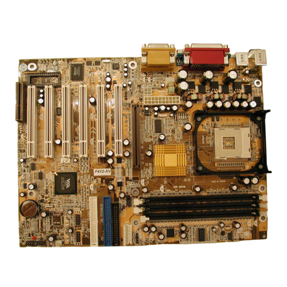
Introduction Chapter 1 Introduction Chapter 1 Chapter 1 Introduction Introduction 1.1. Mainboard and PC99 ATX External Connector Layout AZZA P4X MAINBOARD SERIES Page 5... -
Page 7: Mainboard Overview
1.2.1. Mainboard Series The mainboards in this manual are all Pentium 4 platforms that use a VIA chipset. This manual describes three different models. They are: P4X2-AV ii) P4XA-AV iii) P4XA-BV The differences between these models are shown in the table below. -
Page 8: Features And Specifications
Introduction 1.3. Features and Specifications Processor Supports Intel® Socket 478 Pentium 4. Chipset P4X2-AV: VIA P4X266 + VT8233 VIA P4X266A + VT8233 P4XA-AV: P4XA-BV: VIA P4X266A + VT8233A I/O Chipset For hardware monitoring: Winbond W83697HF CPU Switching Voltage Regulator Equipped with a switching voltage regulator that automatically detects +1.10V to +1.85V DC power supply. - Page 9 USB Ports USB allows data exchange between your computer and a wide range of simultaneously accessible external Plug and Play peripherals. The P4X2-AV and P4XA-AV models are equipped with six (version 1.1) USB connectors. P4XA-BV model is equipped with four (version 1.1) USB connectors.
-
Page 10: System Health Monitor Functions
PCI Bus Master IDE Controller • Two PCI IDE interfaces support up to four IDE devices. • The P4X2-AV and P4XA-AV models support ATA/33, ATA/66 and ATA/100 hard drives. • The P4XA-BV model support ATA/33, ATA/66, ATA/100 and ATA/133 hard drives. -
Page 11: System Intelligence
ACPI Ready The mainboard is designed to meet the ACPI (Advanced Configuration and Power Interface) specification. ACPI has energy saving features that support OS Direct Power Management (OSPM) for round the clock PC operation. Page 10 AZZA P4X MAINBOARD SERIES... -
Page 12: Chapter 2:- Hardware Installation
Universal Serial Bus 3 USB3 CN31 Universal Serial Bus 4 USB4 CN32 Universal Serial Bus 5 USB5 (only for P4X2-AV and P4XA-AV) CN38 Universal Serial Bus 6 USB6 (only for P4X2-AV and P4XA-AV) CN42 System Management Bus (optional) External Connectors... -
Page 13: Installation Steps
We further recommend that you attach an anti- static wristband, which is grounded at the same location as the mat, to your wrist. Only use an ATX 12V Power Supply. Page 12 AZZA P4X MAINBOARD SERIES... -
Page 14: Expansion Cards, Connectors And Jumpers
Hardware Installation 2.3. Expansion Cards, Connectors and Jumpers AZZA P4X MAINBOARD SERIES Page 13... -
Page 15: Cpu, Memory And Expansion Slots
DIMM is in the correct orientation. Place the DIMM on the slot and push down firmly.The white levers will come back up and lock the module in place. Top View of a 184-pin DIMM Slot 40 pins 52 pins Page 14 AZZA P4X MAINBOARD SERIES... -
Page 16: Pci Slots
1066 MB/s. This allows 3D applications to run more smoothly. The P4X2-A mainboards each come with one AGP slot. This slot is able to support 1x, 2x and 4x AGP cards. Top View of an AGP Slot 66 pins AZZA P4X MAINBOARD SERIES Page 15... -
Page 17: Cnr (Communications Network Riser) Slot
IDE devices each. If you install two hard drives, you need to configure the second drive to slave mode in the BIOS setup. Please refer to your hard drive manual for the appropriate jumper settings PIN 1 Top View of an IDE Connector 20 PINS Page 16 AZZA P4X MAINBOARD SERIES... -
Page 18: Standard Infrared Connector
CN15-C power connector is for a +3.3V and +5V power supply. These increased power supplies are necessary to provide extra power for the slot. The ATX 12V power supplies are all downward compatible with standard ATX power supplies. AZZA P4X MAINBOARD SERIES Page 17... -
Page 19: Wol (Wake-On-Lan) And Wom (Wake-On-Modem) Connectors
720 mA and be connected to a “5V standby” voltage. Top View of a WOL/WOM Connec- Front View of a WOL/WOM Con- nector Ground 5V_SB 5V_SB WOL/WOM Ground WOL/WOM Page 18 AZZA P4X MAINBOARD SERIES... -
Page 20: Cd Audio In Connector
The internal USB connectors allow you to add on an optional kit to expand the total number of USB ports available. The P4X2-AV and P4XA-AV have four internal USB connectors (CN30, CN31, CN32 and CN38). This enables you to use an extra 4 USB devices. -
Page 21: Smb Connector
The system will be turned into Suspend mode (turned into the GREEN mode) When the system is in the Suspend mode:- !""" Press the Power on button (less than 4 seconds), the system will return to Full ON mode. Page 20 AZZA P4X MAINBOARD SERIES... -
Page 22: Standby Led Connector
The chassis Power LED connector can be nector nector connected to the four pin connector. When you turn your system on, this LED POWER LED will also be turned on. Top View of the Speaker and Power LED Connector AZZA P4X MAINBOARD SERIES Page 21... -
Page 23: External Connectors
This parallel port is used by printers which support the SPP, EPP and ECP modes IRQ7 or IRQ5 can be selected. The ECP mode will use either DMA 3 or DMA 1 (which can be selected by the BIOS setup program). Page 22 AZZA P4X MAINBOARD SERIES... -
Page 24: Usb 1 And Usb 2 Connectors
Pin 1 and Pin 2 Short Some keyboards may not follow standard specifications. If you find you are hav- ing problems with your keyboard, change the settings on JP 1. This might help you to solve the problem. AZZA P4X MAINBOARD SERIES Page 23... -
Page 25: Jp2: Usb1 And Usb2 Power
Insert the jumper cap on Pin 2 and Pin 3 for 3 ~ 5 seconds. Pull out the jumper cap and replace it on Pin 1 and Pin 2. Turn your PC on and run the BIOS setup program. Page 24 AZZA P4X MAINBOARD SERIES... -
Page 26: Chapter 3:- Managing The Pc Bios
F10 : Save and Exit Setup Time, Date, Hard Disk Type ... Note! BIOS software is continuously updated therefore the BIOS menus and the descriptions that are given in this manual are for reference purposes only. AZZA P4X MAINBOARD SERIES Page 25... -
Page 27: Standard Cmos Setup
This mainboard supports four IDE Hard Drives. These fields allow you to set your Hard Drive parameters. Move the selection bar to the IDE Hard Drive you want to configure. Press the "ENTER" key. If you select “AUTO” the system BIOS will detect the HDD type automatically. Page 26 AZZA P4X MAINBOARD SERIES... - Page 28 If you have not installed one of these drives use the default set- ting. Video This field selects the type of primary video subsystem that is on your computer. The BIOS CMOS Setup Utility will automatically detect the correct video type. AZZA P4X MAINBOARD SERIES Page 27...
-
Page 29: Advanced Bios Features
This BIOS setting can be used to enable or disable the CPU's L1 (primary) and L2 (secondary) cache. CPU L2 Cache ECC Checking When you select Enabled, the ECC checking will ensure that the data stored on the L2 cache is accurate. Page 28 AZZA P4X MAINBOARD SERIES... - Page 30 This field is effective only in systems with two floppy drives. When Enabled is selected physical drive B is assigned to logical drive A, and physical drive A is assigned to logical drive B. AZZA P4X MAINBOARD SERIES Page 29...
- Page 31 2.9.4 on page 24. (Click Here) PS/2 Mouse Function Control If you have installed a serial pointing device and your system has a PS/2 mouse port you should disable this option. Page 30 AZZA P4X MAINBOARD SERIES...
-
Page 32: Advanced Chipset Features
X Bank Interleave Disabled X Precharge to Active (Trp) X Active to Precharge (Tras) X Active to CMD (Trcd) X DRAM Burst Len X DRAM Command Rate [2T Command] X CPU Read DRAM Mode [Medium] AZZA P4X MAINBOARD SERIES Page 31... - Page 33 AGP Aperture Size [128M] Item Help AGP Mode [4X] Menu Level !! AGP Driving Control [Auto] X AGP Driving Value AGP Fast Write [Disabled] AGP Master 1 WS Write [Disabled] AGP Master 1 WS Read [Disabled] Page 32 AZZA P4X MAINBOARD SERIES...
-
Page 34: Agp Driving Control
When enabled, writes to the PCI bus are executed with zero wait states. !PCI Delay Transaction The chipset has an embedded 32-bit posted write buffer to support delay transactions cycles. Select Enabled support compliance with specification version 2.1. AZZA P4X MAINBOARD SERIES Page 33... -
Page 35: Integrated Peripherals
Menu Level ! ! ! ! Primary Master [Auto] Primary Slave [Auto] Secondary MasterPIO [Auto] Secondary Slave PIO [Auto] Primary Master UDMA [Auto] Primary Slave UDMA [Auto] Secondary MasterUDMA [Auto] Secondary Slave UDMA [Auto] Page 34 AZZA P4X MAINBOARD SERIES... - Page 36 Select Enabled if your system has a floppy disk controller (FDC) installed on the system board and you want to use it. If you install an add-in FDC or the system has no floppy drive, select Disabled in this field. AZZA P4X MAINBOARD SERIES Page 35...
- Page 37 Check the IR device’s manual to determine the appropriate setting. !Use IR Pins To determine the correct settings for the TxD and RxD signals of your IR pe- ripheral component, you need to consult the components manual. Page 36 AZZA P4X MAINBOARD SERIES...
- Page 38 This field allows you to enable or disable the onboard USB controller. USB Keyboard Support This field should only be enabled if you are using a USB keyboard. If you are not using this kind of keyboard you should disable it. AZZA P4X MAINBOARD SERIES Page 37...
-
Page 39: Power Management Setup
Allows you to set each mode individually. When not disabled, each of the ranges are from 1 min. to 1 hr. except for HDD Power Down which ranges from 1 min. to 15 min. and disable. Page 38 AZZA P4X MAINBOARD SERIES... - Page 40 IRQ in this field, (officially, COM 1 uses IRQ4, and COM 2 uses IRQ3). Soft-Off by PWRBTN Pressing the power button for more than 4 seconds forces the system to enter the Soft-Off state when the system has “hung”. AZZA P4X MAINBOARD SERIES Page 39...
- Page 41 !Power On by PCI Card The system can be woken up by the PME# on the PCI card. !Modem/LAN Resume An input signal from the modem/LAN will wake up the system from a soft off state. Page 40 AZZA P4X MAINBOARD SERIES...
-
Page 42: Pnp/Pci Configuration
Normally, you leave this field Disabled. If you have installed a new add-on and the system reconfiguration has caused such a serious conflict that the operating system cannot boot then select Enabled. Selecting Enabled will reset the Ex- tended System Configuration Data (ESCD). AZZA P4X MAINBOARD SERIES Page 41... -
Page 43: Pc Health Status
This field allows you to select an operating temperature range for your CPU. If the CPU temperature moves out of this range, any warning mechanism you have programmed into your system will be activated. Page 42 AZZA P4X MAINBOARD SERIES... -
Page 44: Frequency/Voltage Control
CMOS Setup Utility - Copyright (C) 1984 - 2001 Award Software Frequency/Voltage Control CPU Clock Ratio [X 8] Item Help Auto Detect DIMM/PCI Clk [Disabled] Menu Level # # # # " " " " Spread Spectrum [Disabled] CPU Clock [100 MHz] AZZA P4X MAINBOARD SERIES Page 43... -
Page 45: Load Fail-Safe Defaults
BIOS settings and you are not sure which set- ting is causing the problem then you should choose this option. This will load the minimal performance settings and stabilize your system. Page 44 AZZA P4X MAINBOARD SERIES... -
Page 46: Load Optimized Defaults
The “SUPERVISOR PASSWORD” is for you to control unauthorized access to your BIOS CMOS Setup or Booting into the your PC system. The Supervisor Password option is used together with the Security Option in section 3.5. (click here) AZZA P4X MAINBOARD SERIES Page 45... -
Page 47: Set User Password
← ← ← ← ↑ ↑ ↑ ↑ ↓ ↓ ↓ ↓ → → → → : Select Item Esc : Quit F9 : Menu in BIOS F10 : Save and Exit Setup Time, Date, Hard Disk Type ... Page 46 AZZA P4X MAINBOARD SERIES... -
Page 48: Save & Exit Setup/Exit Without Saving
← ← ← ← ↑ ↑ ↑ ↑ ↓ ↓ ↓ ↓ → → → → : Select Item Esc : Quit F9 : Menu in BIOS F10 : Save and Exit Setup Time, Date, Hard Disk Type ... AZZA P4X MAINBOARD SERIES Page 47... - Page 49 CMOS RAM. If you do not want to save any of the changes, or settings you selected in the BIOS SETUP utility, move the selection bar to the “EXIT WITHOUT SAVING” option. Press the “Enter” key. Then press “Y” Page 48 AZZA P4X MAINBOARD SERIES...
Need help?
Do you have a question about the P4X2-AV and is the answer not in the manual?
Questions and answers