Table of Contents
Advertisement
Quick Links
P4X Mainboard Series
P4X Mainboard Series
P4X Mainboard Series
P4X Mainboard Series
SOCKET 478 DDR ATX Mainboard
P4X2- - - - AV
P4X2
P4X2
P4X2
P4XA- - - - AV
P4XA
P4XA
P4XA
P4XA- - - - BV
P4XA
P4XA
P4XA
Version 1.x
UM-P4X-2AABV-E1
Rev 1.0V
Creation Date: 22 November 2001
P4X MAINBOARD SERIES
AV
AV
AV
AV
AV
AV
BV
BV
BV
Page 1
Advertisement
Table of Contents

Subscribe to Our Youtube Channel
Related Manuals for AZZA P4XA Series


Summary of Contents for AZZA P4XA Series
- Page 1 P4X Mainboard Series P4X Mainboard Series P4X Mainboard Series P4X Mainboard Series SOCKET 478 DDR ATX Mainboard P4X2 P4X2- - - - AV P4X2 P4X2 P4XA P4XA- - - - AV P4XA P4XA P4XA P4XA P4XA P4XA- - - - BV Version 1.x UM-P4X-2AABV-E1 Rev 1.0V...
- Page 2 User Notice Copyright This publication contains information that is protected by copyright. No part of it may be reproduced in any form or by any means or used to make any transforma- tion adaptation without prior written permission from the copyright holders. This publication is provided for informational purposes only.
-
Page 3: Table Of Contents
Table Of Contents Chapter 1:- Introduction Page 5 1.1. Mainboard Layout ..................5 1.2. Mainboard Overview ................. 6 1.2.1. Mainboard Series ................... 6 1.2.2. Mainboard Dimensions ................6 1.2.3. Environmental Limitations ............... 6 1.3. Features and Specifications ..............7 1.4. System Health Monitor Functions ............. 9 1.5. - Page 4 Table Of Contents 2.7. Speaker and Power LED Connector ............21 2.7.1. Speaker Connector .................. 21 2.7.2. Front Panel Power LED Connector ............21 2.8. External Connectors .................. 22 2.8.1. PS/2 Keyboard Connector ............... 22 2.8.2. PS/2 Mouse Connector ................22 2.8.3.
-
Page 5: Chapter 1:- Introduction
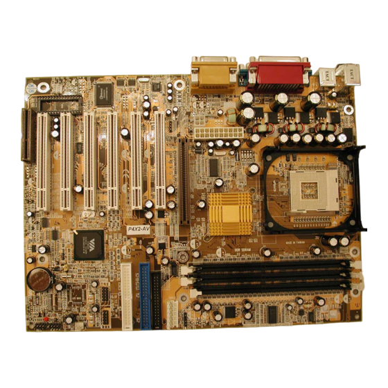
Introduction Chapter 1 Chapter 1 Introduction Introduction Chapter 1 Introduction 1.1. Mainboard and PC99 ATX External Connector Layout P4X MAINBOARD SERIES Page 5... -
Page 6: Mainboard Overview
Introduction PC 99 ATX External Connector CN 5: LPT CN18: Game/MIDI Port CN 7: USB 2 CN 2: PS/2 MS CN 1: PS/2 KB CN 6: USB 1 CN 3: COM 1 CN 4: COM 2 SPK-OUT LINE-IN MIC-IN 1.2. Mainboard Overview 1.2.1. -
Page 7: Features And Specifications
Introduction 1.3. Features and Specifications Processor Supports Intel® Socket 478 Pentium 4. Chipset P4X2-AV: VIA P4X266 + VT8233 P4XA-AV: VIA P4X266A + VT8233 P4XA-BV: VIA P4X266A + VT8233A I/O Chipset For hardware monitoring: Winbond W83697HF CPU Switching Voltage Regulator Equipped with a switching voltage regulator that automatically detects +1.10V to +1.85V DC power supply. - Page 8 Introduction Desktop Management Interface (DMI) The mainboard comes with DMI 2.0 built into the BIOS. The DMI utility in the BIOS will automatically record different information about your system configu- ration and store this information in the DMI pool, which is a part of the system board's Plug and Play BIOS.
-
Page 9: System Health Monitor Functions
Introduction ATX Double Deck Ports (PC 99 color-coded connectors • Two USB ports. • Two external DB-9 serial port connectors: COM 1 and COM 2 (UART). • One SPP/ECP/EPP DB-25 parallel port. • One mini-DIN-6 PS/2 mouse port. • One mini-DIN-6 PS/2 keyboard port. •... -
Page 10: System Intelligence
Introduction 1.5. System Intelligence Dual Function Power Button Depending on the setting in the Soft-Off By Power-Button field of the Power Management Setup, this switch allows the system to enter the Soft-Off or Suspend mode. External Modem Ring-on (optional) The Modem Ring-on feature allows the system that is in the Suspend mode or Soft Power Off mode to wake-up/power-on to respond to incoming calls. -
Page 11: Chapter 2:- Hardware Installation
Hardware Installation Chapter 2 Chapter 2 Hardware Installation Hardware Installation Chapter 2 Hardware Installation 2.1. Installation Checklist The following is a checklist of all the expansion slots, jumpers and connectors that should be configured on your mainboard before you can run your pc. Installation Checklist Expansion Slots and Sockets CPU Slot... -
Page 12: Installation Steps
Hardware Installation Installation Checklist (Continued) System Panel Buttons and LED Connectors Power On/Off and Suspend Switch Connector. Standby LED Connector HDD LED Connector Reset Button Connector Speaker and Power LED Connector PWR-LED Power LED Speaker Connector Jumpers Keyboard Power USB 1 and 2 Power JP4/JP5 CPU FSB Selection JP13... -
Page 13: Expansion Cards, Connectors And Jumpers
Hardware Installation 2.3. Expansion Cards, Connectors and Jumpers P4X MAINBOARD SERIES Page 13... -
Page 14: Cpu, Memory And Expansion Slots
Hardware Installation 2.4. CPU, Memory and Expansion Slots 2.4.1. Installation of the CPU To install your processor, please complete the following set of instructions Locate a small dot marked on the top of the CPU. This mark indicates Pin 1 of the CPU. Locate Pin 1 for the Socket on the mainboard. -
Page 15: Pci Slots
Hardware Installation Important: The DIMM’s can only be fitted into the slots in one orientation. Make sure that the DIMM’s are in the correct orientation and the pins are correctly aligned before you insert them. NOTE: “Out Of Memory” Error Message If you have installed more than 512 MB of RAM and are running Microsoft Windows Millennium Edition, Win- dows 98 Second Edition, Windows 98 or Windows 95 you may experience memory problems. -
Page 16: Cnr (Communications Network Riser) Slot
Hardware Installation 2.4.5. CNR Slot (optional for P4XA-BV) These slots integrate audio, modem and networking on the same card. specifications support the Audio Codec 97 (AC 97) interface, LAN interfaces, USB interfaces and System Management Bus (SMB) interfaces (used specifically to provide Plug and Play functionality). -
Page 17: Standard Infrared Connector
Hardware Installation 2.5.3. Standard Infrared Connector (Optional ) Connector: CN 12 Type: 5 pin The SIR connector supports an optional wireless transmitting and receiving mod- ule. You must configure UART 2 to select whether UART 2 is directed for use with COM 2 or IrDA. -
Page 18: Wol (Wake-On-Lan) And Wom (Wake-On-Modem) Connectors
Hardware Installation ATX12V Power Supply Connector ATX12V Power Supply Connector +5VDC +12VDC +12VDC +5VSB +5VDC +12VDC PWR_OK -5VDC Pin 1 Pin 3 +5VDC Auxiliary Power Supply Connector +5VDC Pin 6 +5VDC PS_ON# +3.3VDC Pin 5 +3.3VDC Pin 4 +3.3VDC -12VDC Pin 3 +3.3VDC +3.3VDC... -
Page 19: Cd Audio In Connector
Hardware Installation 2.5.7. CD Audio-in Connector Connector: CN 21 Type: 4 pin un-housed This mainboard has one CD Audio-in connectors. This connector is used to con- nect the CD ROM audio out. Top View of a CD Audio In Front View of a CD Audio In Connector Connector Left Channel... -
Page 20: Smb Connector
Hardware Installation 2.5.9. SMB (System Management Bus) Connector (optional) Connector: CN 42 Type: 4 pin The SMB is a 2-wire specification which allows for communications between an external UPS or other power devices and a computer. Each of these mainboards has a SMB connector onboard, which can be connected to other SMB devices . -
Page 21: Standby Led Connector
Hardware Installation !"" Press and hold the Power On Button for more than 4 seconds, the system will be powered off. Mode 2: Press and hold the Power ON button for more than 4 seconds, the sys- tem will be completely powered off. Option 2: If you choose “Instant OFF.”... -
Page 22: External Connectors
Hardware Installation 2.8. External Connectors CN 5: LPT CN18: Game/MIDI Port CN 7: USB 2 CN 2: PS/2 MS CN 1: PS/2 KB SPK-OUT LINE-IN MIC-IN CN 6: USB 1 CN 3: COM 1 CN 4: COM 2 2.8.1. PS/2 Keyboard connector. Connector: CN 1 Type:... -
Page 23: Usb 1 And Usb 2 Connectors
Hardware Installation 2.8.5. Universal Serial Bus (USB) Port 1 & 2 Connector: CN 6 (USB 1)/ CN 7 (USB 2) 4 pin female Type: Two USB ports are available for connecting USB devices. The mainboard is also equipped with an expansion connector that supports four additional USB external connectors. -
Page 24: Jp2: Usb1 And Usb2 Power
Hardware Installation 2.9.2. JP2: USB 1 and USB 2 power Type: 3 pin Pin 1 and Pin 2 Short Default: This jumper allows you to select the voltage that is supplied to USB 1 and USB 2. You have two choices: 5 V (pin 1 and pin 2 short) or standby 5 V (pin 2 and pin 3 short). -
Page 25: Chapter 3:- Managing The Pc Bios
Managing The PC BIOS Chapter 3 Chapter 3 Managing the PC BIOS Managing the PC BIOS Chapter 3 Managing the PC BIOS 3.1. Award BIOS CMOS Setup Utility Once you have installed the mainboard you still need to setup the BIOS before you can run your PC. -
Page 26: Standard Cmos Setup
Managing The PC BIOS Navigation Keys You will notice a legend bar at the bottom of the main menu. The keys in this legend bar show you how to navigate through the setup menus. The table below lists the control keys with their corresponding functions: - Control Key Function Up Arrow... - Page 27 Managing The PC BIOS CMOS Setup Utility - Copyright ( C ) 1984 - 2001 Award Software Standard CMOS Features Date (mm : dd : yy) Wed, Nov 21, 2001 Item Help Time (hh : mm : ss) 13 : 9 : 16 Menu Level ! !IDE Primary Master [QUANTUM FIREBALL PKA]...
-
Page 28: Advanced Bios Features
Managing The PC BIOS Monitors EGA/VGA Enhanced Graphics Adapter/Video Graphics Array. For EGA, VGA , SEGA, SVGA or PGA monitor adapters CGA 40 Color Graphics Adapter power up in 40 column mode CGA 80 Color Graphics Adapter power up in 80 column mode MONO Monochrome adapter includes high resolution monochrome adapters Halt On... - Page 29 Managing The PC BIOS CMOS Setup Utility - Copyright ( C ) 1984 – 2001 Award Software. Advanced BIOS Features Virus Warning [Disabled] CPU L1 & L2 Cache [Enabled] Menu Level ! CPU L2 Cache ECC Checking [Enabled] Quick Power On Self Test [Enabled] First Boot Device [Floppy]...
- Page 30 Managing The PC BIOS Boot Up Floppy Seek When enabled, the BIOS tests (seeks) floppy drives to determine whether they have 40 or 80 tracks. Only 360-KB floppy drives have 40 tracks; drives with 720 KB, 1.2 MB, and 1.44 MB capacity all have 80 tracks. Very few modern PCs have 40-track floppy drives so we therefore recommend that you set this field to Disabled to save time.
-
Page 31: Advanced Chipset Features
Managing The PC BIOS OS Select For DRAM > 64MB Only select OS2 if you are running an OS/2 operating system with a RAM greater than 64 Mb. Otherwise, for all other operating systems, use the default setting “Non-OS2” HDD S.M.A.R.T Capability (Using this feature may decrease system performance) You may “enable”... - Page 32 Managing The PC BIOS !Current FSB Frequency The setting for this field will be automatically selected by the BIOS. The value that the BIOS selects depends on the settings you have chosen for JP4 and JP5. If you have a 100 MHz CPU but have and set JP4 to OPEN and JP5 to SHORT the BIOS will detect 133 MHz.
- Page 33 Managing The PC BIOS !AGP Aperture Size This field selects the size of the Accelerated Graphics Port (AGP) aperture. The aperture is a portion of the PCI memory address range dedicated for graphics memory address space. Host cycles that hit the aperture range are forwarded to the AGP without any translation.
-
Page 34: Integrated Peripherals
Managing The PC BIOS Memory Hole You can reserve this area of system memory for ISA adapter ROM. When this area is reserved, it cannot be cached. The user information of peripherals that need to use this area of system memory usually discusses their memory requirements. - Page 35 Managing The PC BIOS !OnChip IDE Channel 0/1 The chipset contains a PCI IDE interface with support for two IDE channels. To activate the primary IDE interface select Enabled. If you want to disable the onboard IDE 1 and/or 2, then select Disabled and this interface will be deactivated !IDE Prefetch Mode The onboard IDE drive interfaces supports IDE pre-fetching for faster drive...
- Page 36 Managing The PC BIOS CMOS Setup Utility - Copyright (C) 1984 - 2001 Award Software SuperIO Device Onboard FDC Controller [Enabled] Item Help Onboard Serial Port 1 [3F8/IRQ4] Onboard Serial Port 2 [2F8/IRQ3] Menu Level !! UART Mode Select [Normal] X RxD, TxD Active Hi, Lo X IR Transmission Delay...
- Page 37 Managing The PC BIOS !Onboard Parallel Port This item allows you to determine the I/O address and the IRQ for the on- board parallel port. The default settings are adequate and should not give you any problems. If they do you can try to change them. !Parallel Port Mode This field allows you to select an operating mode for the onboard parallel (printer) port.
-
Page 38: Power Management Setup
Managing The PC BIOS IDE HDD Block Mode Block mode is also known as block transfer, multiple commands, or multiple sec- tor read/write. If your IDE hard drive supports block mode select “Enabled” for automatic detection of the optimal number of block read/writes per sector the drive can support. - Page 39 Managing The PC BIOS HDD Power Down When enabled and after the set time of system inactivity, the hard disk drive will be powered down while all other devices remain active. Suspend Mode When enabled, after the set time of system inactivity, all devices except the CPU will be shut off.
- Page 40 Managing The PC BIOS PWRON After PWR-Fail Off: When the power returns after an AC power failure the system’s power is off. You must press the Power button to power-on the system F o r m e r - When power returns after an AC power failure, the system will return to the Sts: state where you left off before the power failure occurred.
-
Page 41: Pnp/Pci Configuration
Managing The PC BIOS !RTC Alarm Resume When enabled, you can use the following two fields to select the time and date to wake up the PC system from power saving mode. !Date (of Month)/Resume Time (hh:mm:ss) When RTC Alarm Resume is enabled, your can set the date and time at which the RTC (real-time clock) alarm awakens the system from Suspend mode. -
Page 42: Pc Health Status
Managing The PC BIOS CMOS Setup Utility - Copyright (C) 1984 - 2001 Award Software PNP/PCI Configurations PNP OS Installed [No] Item Help Reset Configuration Data [Disabled] Menu Level #" " Resources Controlled By [Auto(ESCD)] Select Yes if you are using ×... -
Page 43: Frequency/Voltage Control
Managing The PC BIOS CMOS Setup Utility - Copyright (C) 1984 - 2001 Award Software PC Health Status CPU Warning Temperature [Disabled] Item Help º º Current CPU Temperature C/113 Menu Level #" Current CPU FAN Speed 4821 RPM Current CHASSIS FAN Speed 0 RPM Vcore (V) 1.74 V... -
Page 44: Load Fail-Safe Defaults
Managing The PC BIOS CPU Clock Ratio This field allows you to select the clock ratio. Most CPU clock ratios are fixed in- side the CPU by the manufacturers that prohibit you to make any changes. In this case, the setting in this field will make no change to the CPU clock ratio since it locks and is automatically determined by the CPU. -
Page 45: Load Optimized Defaults
Managing The PC BIOS 3.12. Load Optimized Defaults CMOS Setup Utility – Copyright ( C ) 1984 - 2001 Award Software !Standard CMOS Features !Frequency/Voltage Control !Advanced BIOS Features Load Fail-Safe Defaults !Advanced Chipset Features Load Optimized Defaults !Integrated Peripherals Set Supervisor Password !Power Management Setup Set User Password... -
Page 46: Set User Password
Managing The PC BIOS CMOS Setup Utility – Copyright ( C ) 1984 - 2001 Award Software !Standard CMOS Features !Frequency/Voltage Control !Advanced BIOS Features Load Fail-Safe Defaults !Advanced Chipset Features Load Optimized Defaults !Integrated Peripherals Set Supervisor Password !Power Management Setup Set User Password !PNP/PCI Configuration Save &... -
Page 47: Save & Exit Setup/Exit Without Saving
Managing The PC BIOS The User Password can be used to check the user's authority. However, this password entry is different from the "SUPERVISOR PASSWORD". The User Pass- word has a different function to the "Supervisor Password" and the "Security Op- tion"... - Page 48 Managing The PC BIOS Save & Exit Setup This option will save all the setup values to CMOS RAM and exit the SETUP util- ity. Move the selection bar to “SAVE & EXIT SETUP” and press the “Enter” key, then type “Y” and press the “Enter” key again. The values you have entered will be saved and all the information stored in the CMOS memory.
Need help?
Do you have a question about the P4XA Series and is the answer not in the manual?
Questions and answers