
Related Manuals for Aaeon ACP-5215


Summary of Contents for Aaeon ACP-5215
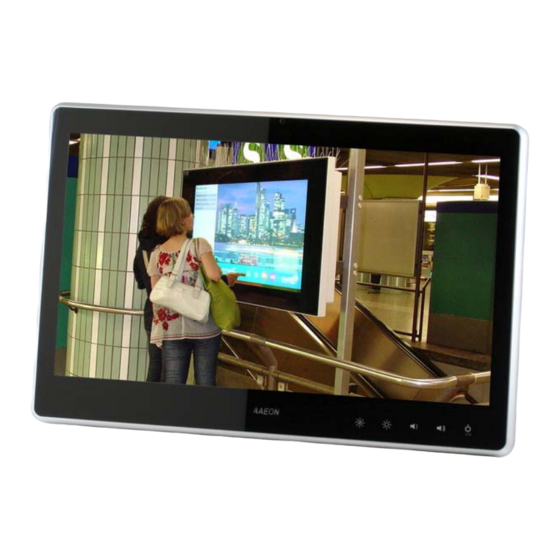
- Page 1 M u l t i - T o u c h P a n e l P C A C P - 5 2 1 5 ACP-5215 21.5” Fanless Multi-Touch Panel PC ® Intel Core i7/i5/ P4500 Processor High Brightness ACP-5215 Manual 3rd Ed June 2012...
-
Page 2: Copyright Notice
AAEON, assumes no liabilities resulting from errors or omissions in this document, or from the use of the information contained herein. AAEON reserves the right to make changes in the product design without notice to its users. - Page 3 M u l t i - T o u c h P a n e l P C A C P - 5 2 1 5 Acknowledgments ® ® Intel , Core are registered trademarks of Intel Corporation. ® ®...
-
Page 4: Packing List
A C P - 5 2 1 5 Packing List Before you begin installing your Panel PC, please make sure that the following items have been shipped: ACP-5215 Infotainment Multi-Touch Panel PC HDD screws Product DVD Contains User’s Manual (in PDF format), Drivers and... - Page 5 M u l t i - T o u c h P a n e l P C A C P - 5 2 1 5 Safety & Warranty 1. Read these safety instructions carefully. 2. Keep this user's manual for later reference. 3.
- Page 6 M u l t i - T o u c h P a n e l P C A C P - 5 2 1 5 14. If any of the following situations arises, get the equipment checked by service personnel: a.
- Page 7 M u l t i - T o u c h P a n e l P C A C P - 5 2 1 5 Classification 1. Degree of production against electric shock: not classified 2. Degree of protection against the ingress of water: IPX1 3.
- Page 8 M u l t i - T o u c h P a n e l P C A C P - 5 2 1 5 This device complies with Part 15 FCC Rules. Operation is subject to the following two conditions: (1) this device may not cause harmful interference, and (2) this device must accept any interference received...
- Page 9 M u l t i - T o u c h P a n e l P C A C P - 5 2 1 5 UL Module Description ACP-5215 AC modules are developed to suitable for the Classification Mark requirement...
- Page 10 M u l t i - T o u c h P a n e l P C A C P - 5 2 1 5 Safety Symbol Description The following safety symbols are further explanations for your reference. Medical equipment with respect to electric shock, fire and mechanical hazards only in accordance with UL 60601-1, and CAN/CSA C22.2 NO.
- Page 11 M u l t i - T o u c h P a n e l P C A C P - 5 2 1 5 Below Table for China RoHS Requirements 产品中有毒有害物质或元素名称及含量 AAEON Panel PC/ Workstation 有毒有害物质或元素 部件名称 铅...
-
Page 12: Table Of Contents
1.4 General Information........... 1-7 Chapter 2 Hardware Installation 2.1 Safety Precautions ............ 2-2 2.2 A Quick Tour of the ACP-5215........2-3 2.3 2.5” Hard Disk Drive (HDD) Installation ....2-5 Chapter 3 AMI BIOS Setup 3.1 System Test and Initialization ........3-2 3.2 AMI BIOS Setup. - Page 13 M u l t i - T o u c h P a n e l P C A C P - 5 2 1 5 B.3 IRQ Mapping Chart ..........B-5 B.4 DMA Channel Assignments........B-5 Appendix C Miscellanea C.1 General Cleaning Tips .......... C-2 C.2 Cleaning Tools............
- Page 14 M u l t i - T o u c h P a n e l P C A C P - 5 2 1 5 Chapter General Information Chapter 1 General Information...
-
Page 15: Chapter 1 General Information
The ACP-5215 includes all the features of a powerful computer into a slim and attractive chassis. The ACP-5215 has 250 nits TFT display with 1920x1080 resolution. This model equips two-point Multi-Touch Window design and is easy to clean. -
Page 16: Features
M u l t i - T o u c h P a n e l P C A C P - 5 2 1 5 1.2 Features 21.5” Full HD (1920x1080) Fanless TFT LCD Display Easy-To-Clean: Multi-Touch Window Design (Two-Point) ®... -
Page 17: Specification
M u l t i - T o u c h P a n e l P C A C P - 5 2 1 5 1.3 Specification System ® Processor Intel Core™ i7/i5/P4500 Processor, Core™ i7-620M, Core™i5-520M, P4500 ... - Page 18 M u l t i - T o u c h P a n e l P C A C P - 5 2 1 5 348.1mm x 56mm) Net Weight 17.38 lb (7.9 kg) Gross Weight 22.44 lb (10.2 kg) Environmental ...
- Page 19 M u l t i - T o u c h P a n e l P C A C P - 5 2 1 5 Backlight MTBF (Hours) 50,000 Touchscreen Type Projected Capacitive Multi-Touch ® (Windows Light Transmission Chapter 1 General Information...
-
Page 20: General Information
M u l t i - T o u c h P a n e l P C A C P - 5 2 1 5 1.4 General Information 1.3M Camera LCD On/Off Volume+ Volume- Brightness+ RFID Brightness- VESA 100 Speaker Speaker Chapter 1 General Information... - Page 21 M u l t i - T o u c h P a n e l P C A C P - 5 2 1 5 COM x 1 Line-out Power Input Power Switch Smart Card Reader USB x 4 LAN x 2 USB x 2 Antenna...
-
Page 22: Chapter 2 Hardware Installation
M u l t i - T o u c h P a n e l P C A C P - 5 2 1 5 Chapter Hardware Installation Chapter 2 Hardware Installation... -
Page 23: Safety Precautions
M u l t i - T o u c h P a n e l P C A C P - 5 2 1 5 2.1 Safety Precautions Always completely disconnect the power cord from your board whenever you are working on it. -
Page 24: A Quick Tour Of The Acp-5215
M u l t i - T o u c h P a n e l P C A C P - 5 2 1 5 2.2 A Quick Tour of the ACP-5215 Mechanical Drawings Front Chapter 2 Hardware Installation... - Page 25 M u l t i - T o u c h P a n e l P C A C P - 5 2 1 5 Rear Cable Cover (Optional) Chapter 2 Hardware Installation...
- Page 26 M u l t i - T o u c h P a n e l P C A C P - 5 2 1 5 Note 1: You may turn on the power by cutting and destroying the protective cover as it shows below.
-
Page 27: Hard Disk Drive (Hdd) Installation
M u l t i - T o u c h P a n e l P C A C P - 5 2 1 5 2.3 2.5” Hard Disk Drive (HDD) Installation Step 1: Unscrew the rear cover screws (15 screws) Step 2: Remove EMI Cover (4 screws) Chapter 2 Hardware Installation... - Page 28 M u l t i - T o u c h P a n e l P C A C P - 5 2 1 5 Step 3: Remove HDD Bracket (4 screws) Step 4: Get the HDD and HDD Bracket ready Chapter 2 Hardware Installation...
- Page 29 M u l t i - T o u c h P a n e l P C A C P - 5 2 1 5 Step 5: Fasten the four screws to fix HDD Bracket and HDD Step 6: Connect the SATA and power cables to the HDD and fasten the four screws to fix the HDD Bracket Chapter 2 Hardware Installation...
-
Page 30: Chapter 3 Ami Bios Setup
M u l t i - T o u c h P a n e l P C A C P - 5 2 1 5 Chapter BIOS Setup Chapter 3 AMI BIOS Setup 3-1... -
Page 31: System Test And Initialization
3. The CMOS memory has lost power and the configuration information has been erased. The ACP-5215 CMOS memory has an integral lithium battery backup for data retention. However, you will need to replace the complete unit when it finally runs down. -
Page 32: Ami Bios Setup
M u l t i - T o u c h P a n e l P C A C P - 5 2 1 5 3.2 AMI BIOS Setup AMI BIOS ROM has a built-in Setup program that allows users to modify the basic system configuration. -
Page 33: Chapter 4 Driver Installation
M u l t i - T o u c h P a n e l P C A C P - 5 2 1 5 Chapter Driver Installation Chapter 4 Driver Installation... - Page 34 M u l t i - T o u c h P a n e l P C A C P - 5 2 1 5 The ACP-5215 comes with an AutoRun DVD-ROM that contains all drivers and utilities that can help you to install the driver automatically.
- Page 35 M u l t i - T o u c h P a n e l P C A C P - 5 2 1 5 4.1 Installation: Insert the ACP-5215 DVD-ROM into the DVD-ROM drive. Then install the drivers from Step 1 to Step 8 in order. Step 1 – Install Chipset Driver Click on the STEP1–CHIPSET folder and select the OS...
- Page 36 M u l t i - T o u c h P a n e l P C A C P - 5 2 1 5 Double click on the Autorun.exe located in each OS folder Follow the instructions that the window shows The system will help you install the driver automatically Step 4 –Install ME Driver Click on the STEP4–ME folder and select the OS folder...
- Page 37 M u l t i - T o u c h P a n e l P C A C P - 5 2 1 5 The system will help you install the driver automatically Step 7 – Install Smart Card Reader Driver (Optional) 1.
-
Page 38: Appendix A Programming The Watchdog Timer
M u l t i - T o u c h P a n e l P C A C P - 5 2 1 5 Appendix Programming the Watchdog Timer Appendix A Programming the Watchdog Timer A-1... -
Page 39: Programming
M u l t i - T o u c h P a n e l P C A C P - 5 2 1 5 A.1 Programming ACP-5215 utilizes ITE 8781 chipset as its watchdog timer controller. Below are the procedures to complete its configuration and the AAEON initial watchdog timer program is also attached based on which you can develop customized programs to fit your application. - Page 40 M u l t i - T o u c h P a n e l P C A C P - 5 2 1 5 There are three steps to complete the configuration setup: (1) Enter the MB PnP Mode; (2) Modify the data of configuration registers; (3) Exit the MB PnP Mode.
- Page 41 M u l t i - T o u c h P a n e l P C A C P - 5 2 1 5 WatchDog Timer Configuration Registers Configure Control (Index=02h) This register is write only. Its values are not sticky; that is to say, a hardware reset will automatically clear the bits, and does not require the software to clear them.
- Page 42 M u l t i - T o u c h P a n e l P C A C P - 5 2 1 5 Watch Dog Timer 1, 2, 3 Configuration Register (Index=72h, 82h, 92h Default=001s0000b) Watch Dog Timer 1,2,3 Time-Out Value (LSB) Register (Index=73h,83h,93h, Default=38h) Watch Dog Timer 1,2,3 Time-Out Value (MSB) Register (Index=74h,84h,94h Default=00h)
-
Page 43: Ite8781 Watchdog Timer Initial Program
M u l t i - T o u c h P a n e l P C A C P - 5 2 1 5 A.2 ITE8781 Watchdog Timer Initial Program .MODEL SMALL .CODE Main: CALL Enter_Configuration_mode CALL Check_Chip mov cl, 7 call Set_Logic_Device ;time setting... - Page 44 M u l t i - T o u c h P a n e l P C A C P - 5 2 1 5 ; game port enable mov cl, 9 call Set_Logic_Device Initial_OK: CALL Exit_Configuration_mode MOV AH,4Ch INT 21h Enter_Configuration_Mode PROC NEAR MOV SI,WORD PTR CS:[Offset Cfg_Port]...
- Page 45 M u l t i - T o u c h P a n e l P C A C P - 5 2 1 5 Exit_Configuration_Mode ENDP Check_Chip PROC NEAR MOV AL,20h CALL Read_Configuration_Data CMP AL,87h JNE Not_Initial MOV AL,21h CALL Read_Configuration_Data CMP AL,81h JNE Not_Initial...
- Page 46 M u l t i - T o u c h P a n e l P C A C P - 5 2 1 5 MOV DX,WORD PTR CS:[Cfg_Port+06h] IN AL,DX Read_Configuration_Data ENDP Write_Configuration_Data PROC NEAR MOV DX,WORD PTR CS:[Cfg_Port+04h] OUT DX,AL XCHG AL,AH MOV DX,WORD PTR CS:[Cfg_Port+06h]...
- Page 47 M u l t i - T o u c h P a n e l P C A C P - 5 2 1 5 push ax push cx xchg al,cl mov cl,07h call Superio_Set_Reg pop cx pop ax Set_Logic_Device endp ;Select 02Eh->Index Port, 02Fh->Data Port Cfg_Port DB 087h,001h,055h,055h...
-
Page 48: Appendix B I/O Information
M u l t i - T o u c h P a n e l P C A C P - 5 2 1 5 Appendix I/O Information Appendix B I/O Information... -
Page 49: I/O Address Map
M u l t i - T o u c h P a n e l P C A C P - 5 2 1 5 B.1 I/O Address Map Appendix B I/O Information... - Page 50 M u l t i - T o u c h P a n e l P C A C P - 5 2 1 5 B - 3 Appendix B I/O Information...
-
Page 51: St Mb Memory Address Map
M u l t i - T o u c h P a n e l P C A C P - 5 2 1 5 B.2 1 MB Memory Address Map Appendix B I/O Information... -
Page 52: Irq Mapping Chart
M u l t i - T o u c h P a n e l P C A C P - 5 2 1 5 B.3 IRQ Mapping Chart B.4 DMA Channel Assignments B - 5 Appendix B I/O Information... -
Page 53: Appendix C Miscellanea
M u l t i - T o u c h P a n e l P C A C P - 5 2 1 5 A ppendix Miscellanea Appendix C Miscellanea C-... -
Page 54: General Cleaning Tips
M u l t i - T o u c h P a n e l P C A C P - 5 2 1 5 C.1 General Cleaning Tips You may need the following precautions before you begin to clean the computer. -
Page 55: Cleaning Tools
M u l t i - T o u c h P a n e l P C A C P - 5 2 1 5 C.2 Cleaning tools Although many companies have created products to help improve the process of cleaning your computer and peripherals users can also use household items to clean their computers and peripherals. - Page 56 M u l t i - T o u c h P a n e l P C A C P - 5 2 1 5 Cotton swabs - Cotton swaps moistened with rubbing alcohol or water are excellent tools for wiping hard to reach areas in your keyboard, mouse, and other locations.
-
Page 57: Scrap Computer Recycling
For the computers that are no longer useful or work well, please contact with worldwide distributors for recycling. The worldwide distributors show on the following website: http://www.aaeon.com/?TabIndex=Contact&TabID=Distributors Note: Follow the national requirements to dispose unit Appendix C Miscellanea... -
Page 58: Installing Accessories
M u l t i - T o u c h P a n e l P C A C P - 5 2 1 5 C.4 Installing Accessories Skype Phone Installation Step 1: Fasten the two screws(2-SELF TAPPING SCREWS) to fix the Skype Bracket with the ACP-5215 Appendix C Miscellanea C-... - Page 59 M u l t i - T o u c h P a n e l P C A C P - 5 2 1 5 MSR Installation Step 1: Fasten the two screws (2-SELF TAPPING SCREWS) to fix the MSR Bracket with the ACP-5215 Appendix C Miscellanea...
- Page 60 M u l t i - T o u c h P a n e l P C A C P - 5 2 1 5 Bar Code Scanner Installation Step 1: Fasten the three screws to fix the Bar Code Scanner with the backet Appendix C Miscellanea C-...
- Page 61 A C P - 5 2 1 5 A C P - 5 2 1 5 Step 2: Fasten the two screws (2-SELF TAPPING SCREWS) to fix the Bar Code Scanner with the ACP-5215 Appendix C Miscellanea Appendix C Miscellanea...
Need help?
Do you have a question about the ACP-5215 and is the answer not in the manual?
Questions and answers