Table of Contents
Advertisement
Advertisement
Table of Contents

Related Manuals for Plura PHB-207-3G


Summary of Contents for Plura PHB-207-3G
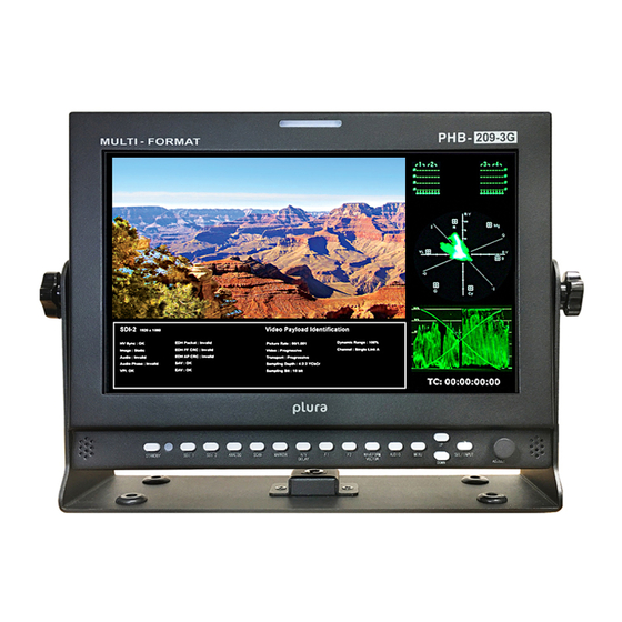
- Page 1 Operating PHB-3G Series Instructions PHB-207-3G PHB-3G Series Monitors PHB-209-3G...
-
Page 2: Table Of Contents
Contents Safety Precautions ....................... 5 1. Overview ........................7 2. General features ....................7 3. Functional Explanation of each Part............8 3-1. Front Panel..................... 8 3-2. Front Keys arrangements ................9 3-3. Front Keys Operations.................. 10 3-4. Front panel LED Operations ................. 10 3-5. - Page 3 Contents continued 9. Audio Menu Options ..................... 20 9-1. SDI 1/ SDI 2 Audio Group ................20 9-2. SDI 1/ SDI 2 Audio Output Channel............. 20 9-3. Level Meter ....................20 9-4. Level Meter Type ..................20 9-5. Level Meter Position ..................20 9-6.
- Page 4 14-5. SETUP ...................... 41 14-6. PIP......................42 15. Supported Input Modes………..................43 15-1. Supported Signals..................43 15-2. SDI Input ....................44 15-3. PC & DVI Input ..................45 16. Mechanical Dimension……..................46 16-1. PHB-207-3G ..................... 46 16-2. PHB-209-3G ..................... 46...
-
Page 5: Safety Precautions
Matrix LcD 8. Attachments permanently. Do not use attachments not recommended by Plura Broadcast inc. as they may cause hazards. 9. Ventilation Do not block any of the ventilation openings. - Page 6 Safety Precautions to qualified service personnel. if the Set does not 11. Power lead Polarization operate properly, switch it off and call your dealer. this product is equipped with a three-wire grounding- type cord. this is a safety feature. Do not defeat the safety 18.
-
Page 7: Overview
SMPTE, EBU, REC 709 Broadcast Standards. The standard calibration feature enables gamma, color temperature and white luminance level adjustments to meet all Broadcast standards. The PHB-3G is compatible with Plura (ICAC) calibration tool and provides 10 bit look up table (LUT) (1024 steps of grayscale). -
Page 8: Functional Explanation Of Each Part
3. Functional explanation of each Part Front panel 3-1. Front View PHB-207-3G Front View PHB-207-3G... -
Page 9: Front Keys Arrangements
3. Functional explanation of each Part 3-2. Front Key Arrangements 3-3. Front Key Operations Key Name Operation Power on/off Button. This button is operated after being pressed about 3 seconds. Stand By activates OSD menu of input source selecting. changes input source. SEL/INPUT executes functions (by OSD help commands) in main OSD menu. -
Page 10: Rear Panel
3. Functional explanation of each Part continued 3-5. Rear Panel 3-6. Connection details Rear Panel 3-7. DC 12V Battery IN PIN No. description 2, 3 + 12V... -
Page 11: Remote Pin Assignment (Rj-45)
3. Functional explanation of each Part continued 3-8. Remote PIN Assignment 1 Pin Common(GND) 5 Pin GPI 4 Port GPI 7 Port GPI 3 Port 2 Pin 6 Pin (StanD 3 Pin GPI 6 Port 7 Pin GPI 2 Port By/PoWer on/off) 4 Pin... -
Page 12: Menu Overview
4. Menu Overview in this menu system, there are several ways to customize the menu settings provided. Most menus consist of three levels to set up the options, but some require greater depth for the variety of settings. if you press the MENU button, only the first and second level of the menu system will appear on the monitor screen. -
Page 13: Basic Operation
5. Basic Operation 5-1. Turning On the Monitor 1. First, connect power cord correctly. at this moment, the monitor switches to standby or power on mode. in standby mode, in order to turn monitor on, press the St-By button for at least 3 seconds. -
Page 14: On Screen Menu Selection And Adjustment
6. ON Screen Menu Selection And Adjustment 6-1. How to adjust the OSD screen 1. Press the Menu button and then UP/DOWN button to select each menu. 2. Press the SEL/INPUT button and then use UP/DOWN (SEL/INPUT)/Menu button to display the available menus. ( your monitor’s OSD (On Screen display) may differ slightly from what is shown in this manual.) -
Page 15: Select Video Input
7. Select Video Input 7-1. How to Select Video Source by OSD 1. Press the SEL/INPUT button and then UP/DOWN button to select each video source. 2. Press the SEL/INPUT button to go to desired video source. 3. if input name is enabled, the SEL/INPUT button goes into input name edit mode instead of selecting source. -
Page 16: Video Menu Options
8. Video Menu Options 8-1. Video Menu of each Input modes < Video (NTSC) Picture menu> < PC Picture menu> < SDI, HDMI Picture menu> 8-2. Adjust -adjust the values of Brightness, contrast, color, tint and Sharpness directly from -50 to 50 contrast, Brightness, Sharpness, color (all Sources), tint ( Pc, DVI, HDMI, component) n/a, Phase (component) n/a. -
Page 17: Aspect Ratio
continued 8. Video Menu Options continued 8-4. Scan Input: 1080i Panel Resolution: 1366x768 8-5. Aspect Ratio - for Setting the aspect ratio. - full Screen: the images are displayed with a panel size. - full Screen, 16:9, 4:3, 14:9, 13:9, 1.85:1, 2.35:1: the images are displayed with each aspect ratio. - Pc mode: full Screen &... -
Page 18: Zoom
continued continued continued 8. Video Menu Options 8. Video Menu Options 8. Video Menu Options 8-6. Zoom 8-6. Zoom 8-6. Zoom - can see the enlarged video by (2X, 3X, 4X, 5X) ratios. - can see the enlarged video by (2X, 3X, 4X, 5X) ratios. - can see the enlarged video by (2X, 3X, 4X, 5X) ratios. -
Page 19: Flip
continued 8. Video Menu Options 8-9. Flip < H-flip off > < H-flip on > -H-flip Display on/off 8-10. NR (Noise Reduction) -noise reduction on/off. (SDI mode only) 8-11. dual link Mode (SDI Only) -Dual Link Mode select. (auto/off/RGB444/ycbcr444/ycbcr422) - if SDI signal has a video payload identification and Dual Link Mode set auto mode. Dual link is set automatically. -
Page 20: Audio Menu Options
9. Audio Menu Options 9. Audio Menu Options 9. Audio Menu Options 9-1. SDI 1/ SDI 2 Audio Group 9-1. SDI 1/ SDI 2 Audio Group 9-1. SDI 1/ SDI 2 Audio Group - Select primary or secondary Audio group to extract. (Group 1~4) - Select primary or secondary Audio group to extract. -
Page 21: Level Meter Scale
continued 9. Audio Menu Options 9-6. level Meter Scale - Level Meter Scale mode selects. (BBC / EBU / Vu / NORDIC / DIGITAL / DIN / EXPAND DIN) 9-7. Audio Mode - Sound mode selects (Stereo/Dual Mono) -
Page 22: Volume
continued 9. Audio Menu Options 9-8. Volume - adjust the speaker or headphone Volume level. (0~100) -
Page 23: Marker Menu Options
10. Marker Menu Options 10. Marker Menu Options 10. Marker Menu Options 10-1. Marker & user Marker 10-1. Marker & user Marker 10-1. Marker & user Marker < Marker > < Marker > < Marker > < User Marker > <... -
Page 24: Center Maker
continued 10. Marker Menu Options 10-3. Center Maker - “+” Marker on center of screen 10-4. Marker Width -Marker line thickness setting. (0~10) 10-5. Marker Color - Mark e r L i n e c o lo r : Se le c t M a r k e r lin e c olor ( W hi te, y e l lo w , Blu e, R ED , Bl a c k ) - Safety Line color: Select Safety line color (White, yellow, Blue, RED, Black) - Marker Back color: Select Marker Back color. -
Page 25: Gpi Menu Options
11. GPI Menu Options 11-1. GPI Control & GPI# - for allocating functions to particular GPI pins. - When remote control operations are to be performed using the GPI controller. - GPI control: GPI function enable/Disable - GPI 1 ~ 7 GPI function description UNDEFINED... -
Page 26: Setup Menu Options
continued 12. Setup Menu Options 12-1. SETUP load & SETUP Save - SETUP Load: Load user saved values or default value - SETUP Save: Save user setting values at user 1, 2, 3. 12-2. function 1 & function 2 & function 3 »... -
Page 27: On Screen Display
continued 12. Setup Menu Options 12-3. On Screen display 12-4. OSD Option » Language: Select a language for the menu to appear in. (English, Spanish, Portuguese, German, French, Italian) » OSD Position: L-T, R-T, C, L-B, R-B » Message OSD: Message OSD display enable/disable »... -
Page 28: Input Name
continued 12. Setup Menu Options 12-7. Input Name Display user name instead of input source name on source OSD and message OSD - example and naming method 1) if input name is enable, user can see the below input Source OSD 2) Press function 3 on the controller to go into name edit mode 3) Make name in 5 characters by UP/DOWN key 12-8. -
Page 29: Advanced
continued 12. Setup Menu Options 12-10. Advanced - information, control, Screen Saver, Screen control, fan control, x768 Mode 12-11. Information - Version, release day, release time and operating time 12-12. Control » front LED: front LED on/off » Local enable: Power, up and down keys are only enabled, when Local enable is off. -
Page 30: Screen Control
continued 12. Setup Menu Options 12-14. Screen Control Auto Calibration for qualified personnel ONLY connects CA-210 (Minolta) with RS-232 and executes an automatic screen regulation. STEPS: 1. Set the baud rate of the probe to 9800. 2. use RS-232 cable and connect to RS-232 in port. 3. -
Page 31: Fan Control
continued 12. Setup Menu Options continued Screen Control 5) Result messages are ‘Not Prepared!!’, ‘fail!!’ and ‘Success!!’. » “not prepared!!” : cannot communication with ca-210 » “fail!!” : cannot search target LV or temp values. Note : » target Lv ( full white is 100 cd/m2), color temperature(3000c~12000c) »... -
Page 32: Caption
continued 12. Setup Menu Options 12-17. Caption closed caption: 608 Line21, 608 anc, 608 transcoded, 708 mode Select 608 caption mode Select. (c/c1, c/c2, c/c3, c/c4, text1, text2, text3, text4, off) 708 caption model select (service 1, service 2) 12-18. Waveform format Press the WAVEFORM button to display the WAVEFORM Mode 12-19. -
Page 33: Double
continued 12. Setup Menu Options 12-21. double SDI 1, 2 & WAVEFORM & Vector Scope & Audio Lever Meter & info Window & time code Display. 12-22. Y-Waveform + Vector Scope trans WAVEFORM & Vector Scope trans. 12-23. Set Id & Active Set Id if control each Board, must Set ID numbers of each Board (01~99). -
Page 34: Pip (Picture In Picture)
13. PIP (Picture In Picture) » Watch two programs or source at the same time. and Set up PIP size and position. » only Dual Link model Select 13-1. PIP ON/Off » control PIP function on/off. 13-2. Input Source » PIP input Source can operate with different signal and type. »... -
Page 35: Pip Blend
continued continued continued 13. PIP (Picture In Picture) 13. PIP (Picture In Picture) 13. PIP (Picture In Picture) 13-5. PIP Blend 13-5. PIP Blend 13-5. PIP Blend -Blend to PIP size of Small -Blend to PIP size of Small -Blend to PIP size of Small 13-6. -
Page 36: Osd Tree
14. OSD Tree... -
Page 37: Video
continued 14. OSD Tree 14-1. Video... -
Page 38: Audio
continued 14. OSD Tree 14-2. Audio... -
Page 39: Marker
continued 14. OSD T ree 14-3. Marker... -
Page 40: Gpi
continued 14. OSD Tree 14-4. GPI... -
Page 41: Setup
continued 14. OSD T ree 14-5. SETUP... -
Page 42: Pip
continued 14. OSD Tree 14-6. PIP... -
Page 43: Supported Input Modes
15. Supported Input Modes 15-1. Supported Signals Items Specifications PBM-207-3G Display Panel 7” TFT LCD Resolution 800 horizontal. by 480 vertical.(contrast 900:1) Brightness 900 cd/m2 Viewing angle RL 178 (Typ), U/D 178 (Typ) PBM-209-3G Display Panel 9” TFT LCD Resolution 800 horizontal. -
Page 44: Sdi Input
continued 15. Supported Input Modes 15-2. SDI input SDI input SDI input SMPTE-428.1M 2048x1080P(24/25) Signal formats SMPTE-425M(3G) 1920x1080P(50/60) SMPTE-260M 1920x1035i(60/59.94) SMPTE-259M 1920x1080i(50) SMPTE-274M 1920x1080i (50/59.94/60) 1920x1080P (30Psf/25Psf/24Psf/30/25/24) SMPTE-296M 1280x720P (24/25/30/50/59.94/60) SMPTE-125M 480i(59.94) ITU-R BT.601 576i(50) 15-3. DVI & PC input Section Resolution h frequency... -
Page 45: Pc & Dvi Input
15. Supported Input Modes Section Resolution h frequency V frequency Pixel frequency Comment ( khz ) ( hz ) ( Mhz ) 640x400 37.861 85.08 31.5 640x350 31.469 70.087 25.175 640x350 37.861 85.08 31.5 640x480 31.469 59.94 25.175 640x480 35.000 66.667 30.24 640x480... -
Page 46: Mechanical Dimension
16. Mechanical dimension 16-1. PHB-207-3G 16-2. PHB-209-3G... - Page 47 ® www.plurabroadcast.com Plura Broadcast, Inc. - West Coast 1930 W. Quail Ave Phoenix, AZ 85027 Tel: (602) 944-1044 Fax: (602) 324-9688 Plura Broadcast, Inc. - East Coast 67 Grand avenue Massapequa, NY 1175 Tel: (516) 997-5675 Fax: (516) 593-7900...
Need help?
Do you have a question about the PHB-207-3G and is the answer not in the manual?
Questions and answers