Table of Contents
Advertisement
Quick Links
Download this manual
See also:
User Manual
Advertisement
Table of Contents

Related Manuals for 4IPNET EAP200


Summary of Contents for 4IPNET EAP200
- Page 1 EAP200 V1. 0 0...
- Page 2 User’s Manual E A P 2 0 0 E n t e r p r i s e A c c e s s P o i n t E N G L I S H Copyright & Disclaimer Copyright The contents of this publication may not be reproduced in any part or as a whole, stored, transcribed in an information retriev al system, translated into any lang uag e, or transmitted in any form or by any means, mechanical, mag netic, electronic, optical, photocopying , manual, or...
-
Page 3: Table Of Contents
User’s Manual E A P 2 0 0 E n t e r p r i s e A c c e s s P o i n t E N G L I S H Table of Contents B e f o r e Y o u S t a r t ..........................4 1.1 P r e f a c e ............................ - Page 4 User’s Manual E A P 2 0 0 E n t e r p r i s e A c c e s s P o i n t E N G L I S H 7 .4 .4 R e b o o t ..........................70 7 .5 S t a t u s ............................
-
Page 5: B Efor E Y Ou S Tar T
This manual is intended for system integrators, field engineers, and network administrators to set up 4ipnet’s EAP200 802.11n/b/g 2.4GHz MIMO Access Point in their network environments. It contains step- by-step procedures and visual examples to guide MIS staff or individuals with basic network system knowledge to complete the installation. -
Page 6: P Ack Age Con Ten T
E n t e r p r i s e A c c e s s P o i n t E N G L I S H 1.3 P ack age Con ten t The standard package of EAP200 includes: •... -
Page 7: S Y Stem O V Er V I Ew And G Etti Ng S Tar Ted
2.1 I n trod u ction of 4ipn et E A P 20 0 The 4ipnet EAP200 Enterprise Access Point embedded with 802.11 n/b/g 2.4GHz MIMO radio in dust- proof metal housing is designed for wireless connectivity in enterprise or industrial environments of all dimensions. -
Page 8: Deploymen T T Opology
This above deployment scenario illustrates a deployment example using three access points, AP-1, AP-2, and AP-3. • Three EAP200 systems construct a network comprising of wired and wireless segments AP-2 plays the role of a wireless bridge. • All devices share the same DHCP server 192.168.1.1. -
Page 9: H Ard W Are Description
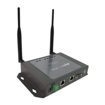
E n t e r p r i s e A c c e s s P o i n t E N G L I S H 2.3 H ard w are Description This section depicts the hardware information including all panel description. Connector Panel Figure 3 EAP200 Connector Panel Disabled for future usage only. Press to start running WES process. Console Attach the serial cable here. - Page 10 E n t e r p r i s e A c c e s s P o i n t E N G L I S H LED Panel Figure 5 EAP200 LED Panel Power LED LED ON indicates power on; OFF indicates power off.
-
Page 11: H Ard W Are I N Stallation
2. Connect the EAP200 to your network device. Connect one end of the Ethernet cable to LAN port of EAP200 and the other end of the cable to a switch, a router, or a hub. EAP200 is then connected to your existing wired LAN network. -
Page 12: A Ccess W Eb M An Agemen T I N Terf Ace
To access the web management interface (WMI), connect the administrator PC to the LAN port of EAP200 via an Ethernet cable. Then, set a static IP Address on the same subnet mask as the EAP200 in TCP/IP settings of your PC, such as the following example: IP Address: 192.168.1.100... - Page 13 E n t e r p r i s e A c c e s s P o i n t E N G L I S H Figure 7 Administrator Login Page After a successful login into EAP200, a System Overview page of the Web Management Interface •...
- Page 14 User’s Manual E A P 2 0 0 E n t e r p r i s e A c c e s s P o i n t E N G L I S H • To logout, simply click on the Logout button at the upper right hand corner of the interface to return to the Administrator Login Page.
- Page 15 • • After the EAP200’s network configuration is completed, please remember to change the IP Address of your PC Connection Properties back to its original settings in order to ensure that your PC functions properly in its real network environments.
-
Page 16: Connec T Y Ou R A P To Y Ou R N Etw Or K
LAN port and provide wireless access to your network. After having prepared the EAP200’s hardware for configuration, set the TCP/IP settings of administrator’s computer to have a static IP Address of 192.168.1.10 and Subnet Mask of 255.255.255.0. - Page 17 User’s Manual E A P 2 0 0 E n t e r p r i s e A c c e s s P o i n t E N G L I S H From here, click on the System icon to arrive at the following page. On this Page you can make entries to the Name, Description, and Location fields as well as set the device’s time.
- Page 18 User’s Manual E A P 2 0 0 E n t e r p r i s e A c c e s s P o i n t E N G L I S H Figure 15 NTP Setup Step 2: Configuring the AP’s Network Settings While still on this Page, click on the Network Interface tab to begin configuration of the network settings.
- Page 19 User’s Manual E A P 2 0 0 E n t e r p r i s e A c c e s s P o i n t E N G L I S H Step 3: Configure the AP’s Wireless General Settings Click on the Wireless icon followed by the General tab.
- Page 20 User’s Manual E A P 2 0 0 E n t e r p r i s e A c c e s s P o i n t E N G L I S H Step 4: Configuring Wireless Coverage (VAP-1) To setup the AP’s wireless access, refer to the following VAP-1 configuration (other VAP configuration can refer to the same setup steps as done for VAP-1).
- Page 21 User’s Manual E A P 2 0 0 E n t e r p r i s e A c c e s s P o i n t E N G L I S H The desired VAP profile can be selected from the drop-down menu of Profile Name and VAP-1 configuration will serve as an example for all other VAPs.
-
Page 22: A D D I Ng V I R Tu Al A C C Ess P Oi Nts
4. A d d i ng V i r tu al A c c ess P oi nts EAP200 possesses the feature of multi-ESSID; namely, it can behave as multiple virtual access points, providing different levels of services from the same physical AP device. - Page 23 User’s Manual E A P 2 0 0 E n t e r p r i s e A c c e s s P o i n t E N G L I S H Figure 21 VAP Configuration Page (VAP-1 shown) Please select the desired VAP profile from the drop-down menu of Profile Name.
-
Page 24: S Ec U R E Y Ou R A P
User’s Manual E A P 2 0 0 E n t e r p r i s e A c c e s s P o i n t E N G L I S H 5. S ec u r e Y ou r A P Different VAP may require different level of security. - Page 25 User’s Manual E A P 2 0 0 E n t e r p r i s e A c c e s s P o i n t E N G L I S H Figure 23 VAP Configuration Page (VAP-1 as shown for example) Select Enable for the VAP field, and click SAVE.
- Page 26 User’s Manual E A P 2 0 0 E n t e r p r i s e A c c e s s P o i n t E N G L I S H • None: Authentication is not required and data is not encrypted during transmission when this option is selected.
- Page 27 User’s Manual E A P 2 0 0 E n t e r p r i s e A c c e s s P o i n t E N G L I S H • 802.1X: When 802.1X Authentication is selected, RADIUS authentication and enhanced dynamic WEP are provided.
- Page 28 User’s Manual E A P 2 0 0 E n t e r p r i s e A c c e s s P o i n t E N G L I S H • WPA-PSK: Provide shared key authenticaiton in WPA data encryption. Figure 28 Security Settings: WPA-PSK Cipher Suite: Select an encryption method from TKIP (WPA), AES (WPA), TKIP (WAP2), AES (WAP2), or Mixed.
- Page 29 User’s Manual E A P 2 0 0 E n t e r p r i s e A c c e s s P o i n t E N G L I S H • WPA-RADIUS: Authenticate users by RADIUS and provide WPA data encryption. Figure 29 Security Settings: WPA-RADIUS WPA Settings: Cipher Suite: Select an encryption method from TKIP (WPA), AES (WPA), TKIP (WAP2), AES...
- Page 30 User’s Manual E A P 2 0 0 E n t e r p r i s e A c c e s s P o i n t E N G L I S H Step 3: Configuring MAC ACL (Access Control List) Clicking on the hyperlink corresponding with intended VAP in the MAC ACL column, the user will be brought to the Access Control Settings page.
- Page 31 User’s Manual E A P 2 0 0 E n t e r p r i s e A c c e s s P o i n t E N G L I S H An empty Allow List means that there are no allowed MAC addresses. Make sure at least the MAC of the modifying system is included (e.g.
- Page 32 User’s Manual E A P 2 0 0 E n t e r p r i s e A c c e s s P o i n t E N G L I S H RADIUS ACL: Authenticate incoming MAC addresses by an external RADIUS server. When RADIUS ACL is selected, all incoming MAC addresses will be authenticated by an external RADIUS server.
-
Page 33: Cr Eate A W D S B R I D G E Betw Een Tw O A P S
WDS link creation will assist to extend network coverage where running wires is not an option, effectively transferring the traffics to the other end of WLAN/LAN through the EAP200. Since this is a peer to peer connection, both EAP200s will be configured by the same way. - Page 34 User’s Manual E A P 2 0 0 E n t e r p r i s e A c c e s s P o i n t E N G L I S H Step 2: Prevent Loops if Connecting Many APs When many APs are linked in this manner, undesired loops may form to lower overall WLAN performance.
- Page 35 M anag em ent I nter fac e Confi g u r ati on This chapter will guide the user through the EAP200’s detailed settings. The following table shows all the User Interface (UI) functions of 4ipnet’s EAP200 Enterprise Access Point. The Web Management Interface (WMI) is the page where the status is displayed, control is issued and parameters are configured.
- Page 36 User’s Manual E A P 2 0 0 E n t e r p r i s e A c c e s s P o i n t E N G L I S H On each configuration page, the user may Click SAVE to save the changes, but the user must reboot the system upon the completion of Note: all configurations for the changes to take effect.
-
Page 37: S Ystem
User’s Manual E A P 2 0 0 E n t e r p r i s e A c c e s s P o i n t E N G L I S H 7 .1 S ystem Upon clicking on the System button, users can work on this section for general configurations of the devices (e.g. - Page 38 E n t e r p r i s e A c c e s s P o i n t E N G L I S H Enable NTP: By selecting Enabled NTP, EAP200 can synchronize its system time with the NTP server automatically. While this method is chosen, at least one NTP server' s IP address or domain name must be provided.
-
Page 39: N E T W O R K I N T E R F A C E
• Layer 2 STP: If the EAP200 is set up to bridge other network components, this option can be enabled to prevent undesired loops because broadcasting storm may occur in a multi-switch environment where broadcast packets are forwarded in an endless loop between switches. Moreover, a broadcast storm may consume most of available system resources in addition to available bandwidth. -
Page 40: M A N A G E M E N T
User’s Manual E A P 2 0 0 E n t e r p r i s e A c c e s s P o i n t E N G L I S H 7.1.3 M a n a g e m e n t The management services (e.g. - Page 41 User’s Manual E A P 2 0 0 E n t e r p r i s e A c c e s s P o i n t E N G L I S H • SNMP Configuration: By enabling SNMP function, the administrator can obtain the system information remotely.
-
Page 42: A P
An overall status is collected on this page, including ESSID, State, Security Type, MAC ACL, and Advanced Settings, where EAP200 features 8 VAPs with respective settings. In this table, please click on the hyperlink to further configure each individual VAP. - Page 43 User’s Manual E A P 2 0 0 E n t e r p r i s e A c c e s s P o i n t E N G L I S H • State: The hyperlink showing Enable or Disable connects to the VAP Configuration page. Figure 44 VAP Overview Page –...
- Page 44 User’s Manual E A P 2 0 0 E n t e r p r i s e A c c e s s P o i n t E N G L I S H • MAC ACL: The hyperlink showing Allow or Disable connects to the Access Control Settings Page. Figure 46 VAP Overview Page –...
-
Page 45: G E N E R A L
User’s Manual E A P 2 0 0 E n t e r p r i s e A c c e s s P o i n t E N G L I S H 7.2 .2 G e n e r a l AP’s general wireless settings can be configured here: Figure 48 AP General Settings Page •... - Page 46 User’s Manual E A P 2 0 0 E n t e r p r i s e A c c e s s P o i n t E N G L I S H • Beacon Interval (ms): The entered amount of time indicates how often the beacon signal will be sent from the access point.
-
Page 47: A P C O N F I G U R A T I O N
ESSID: ESSID (Extended Service Set ID) serves as an identifier for clients to associate with the specific VAP. It can be coupled with different service level like a variety of wireless security types. VLAN ID: EAP200 supports tagged VLANs (virtual LANs). To enable VLAN function, each VAP shall •... -
Page 48: S E C U R I T Y
E n t e r p r i s e A c c e s s P o i n t E N G L I S H 7.2 .4 S e c u r i t y EAP200 supports various wireless authentication and data encryption methods in each VAP profile. With this, the administrator can provide different service levels to clients. The security type includes None, WEP, 802.1X, WPA-PSK, and WPA-RADIUS. - Page 49 User’s Manual E A P 2 0 0 E n t e r p r i s e A c c e s s P o i n t E N G L I S H 802.11 Authentication: Select from Open System, Shared Key, or Auto. WEP Key Length: Select from 64-bit, 128-bit, 152-bit key length.
- Page 50 User’s Manual E A P 2 0 0 E n t e r p r i s e A c c e s s P o i n t E N G L I S H Dynamic WEP Settings: Dynamic WEP: For 802.1X security type, Dynamic WEP is always enabled to automatically generate WEP keys for encryption.
- Page 51 User’s Manual E A P 2 0 0 E n t e r p r i s e A c c e s s P o i n t E N G L I S H WPA-RADIUS: If this option is selected, the RADIUS authentication and data encryption will be both enabled.
-
Page 52: R E P E A T E R
Figure 55 Repeater Settings: Universal Repeater If WDS is selected, EAP200 can support up to 4 WDS links to its peer APs. Security Type (None, WEP, or WPA/PSK) can be configured to decide which encryption to be used for WDS connections respectively. -
Page 53: A D V A N C E D
The RTS mechanism will be activated if the data size exceeds the value provided. A lower RTS Threshold setting can be useful in areas where many client devices are associating with EAP200 or in areas where the clients are far apart and can detect only EAP200 but not each other. - Page 54 This option works with WMM-capable clients only. <To receive the benefits of WMM QoS> The application must support WMM. ▬ WMM shall be enabled on EAP200. ▬ WMM shall be enabled in the wireless adapter on client’s computer. ▬ •...
-
Page 55: A C C E Ss C O N T R O L
7.2 .7 A c c e ss C o n t r o l On this page, the network administrator can restrict the total number of clients connected to the EAP200, as well as specify particular MAC addresses that can or cannot access the device. - Page 56 User’s Manual E A P 2 0 0 E n t e r p r i s e A c c e s s P o i n t E N G L I S H • Access Control Type The administrator can restrict the wireless access of client devices based on their MAC addresses.
- Page 57 User’s Manual E A P 2 0 0 E n t e r p r i s e A c c e s s P o i n t E N G L I S H MAC ACL Deny List: When selecting MAC ACL Deny List, all client devices are granted with access to the system except those listed in the Deny List (“denied MAC addresses”).
- Page 58 User’s Manual E A P 2 0 0 E n t e r p r i s e A c c e s s P o i n t E N G L I S H RADIUS ACL: Authenticate incoming MAC addresses by an external RADIUS. When RADIUS ACL is selected, all incoming MAC addresses will be authenticated by an external RADIUS.
-
Page 59: S I T E S U R V E Y
User’s Manual E A P 2 0 0 E n t e r p r i s e A c c e s s P o i n t E N G L I S H 7.2 .8 S i t e S u r v e y Sit Survey is a useful tool to provide information about the surrounding wireless environment;... - Page 60 User’s Manual E A P 2 0 0 E n t e r p r i s e A c c e s s P o i n t E N G L I S H WPA-PSK: Click Setup to configure the WPA-PSK setting for associating with the target The following configuration box will then appear at the bottom of the screen.
-
Page 61: F Irew All
User’s Manual E A P 2 0 0 E n t e r p r i s e A c c e s s P o i n t E N G L I S H 7 .3 F irew all The system provides an added security feature, Layer2 Firewall, in addition to typical AP security. - Page 62 User’s Manual E A P 2 0 0 E n t e r p r i s e A c c e s s P o i n t E N G L I S H From the overview table, each rule is designated with the following field; No.: The numbering will decide the priority to let system carry out the available firewall rules in the tables.
- Page 63 User’s Manual E A P 2 0 0 E n t e r p r i s e A c c e s s P o i n t E N G L I S H Rule ID: The numbering of this specific rule will decide its priority among available firewall rules in the table.
- Page 64 User’s Manual E A P 2 0 0 E n t e r p r i s e A c c e s s P o i n t E N G L I S H Remark: The note of this rule can be specified here. When the configuration for firewall rule is provided;...
- Page 65 User’s Manual E A P 2 0 0 E n t e r p r i s e A c c e s s P o i n t E N G L I S H Copyr i g h t © 4I P N E T , I N C.
-
Page 66: S E R V I C E
(when EtherType is IPv4). EAP200 provides a list of rules to block or pass traffics of layer-3 or above protocols. These services are available to choose from drop-down list of layer2 firewall rule edit page with Ether Type to be IPv4. The first 28 entries are default services and the administrator can add/delete any extra desired services. -
Page 67: A D V A N C E D
User’s Manual E A P 2 0 0 E n t e r p r i s e A c c e s s P o i n t E N G L I S H 7.3 .3 A d v a n c e d Advanced firewall settings are used to supplement the firewall rules, providing extra security enhancement against DHCP and ARP traffics traversing the available interfaces of system. -
Page 68: U Tilities
User’s Manual E A P 2 0 0 E n t e r p r i s e A c c e s s P o i n t E N G L I S H 7 .4 U tilities The administrator can maintain the system on this page: Change Password, Backup &... -
Page 69: B A C K U P & R E St O R E
R e st o r e This function is used to backup and restore the EAP200 settings. The EAP200 can also be restored to factory defaults using this function. It can be used to duplicate settings to other access points (backup settings of this system and then restore on another AP). -
Page 70: S Y St E M U P G R A D E
7.4.3 S y st e m U p g r a d e The EAP200 provides a web firmware upload / upgrade feature. The administrator can download the latest firmware from the website and save it on the administrator’s PC. To upgrade the system firmware, click Browse to choose the new firmware file you downloaded onto your PC and then click Upload to execute the process. -
Page 71: R E B O O T
7.4.4 R e b o o t This function allows the administrator to restart the EAP200 safely. The process shall take about three minutes. Click Reboot to restart the system. Please wait for the blinking timer to complete its countdown before accessing the system’s Web Management Interface again. -
Page 72: S Tatu S
User’s Manual E A P 2 0 0 E n t e r p r i s e A c c e s s P o i n t E N G L I S H 7 .5 S tatu s This page is used to view the current condition and state of the system and includes the following functions: Overview, Associated Clients, Repeater and Event Log. -
Page 73: System Location
Table 3 Status Page's Organizational Layout Item Description System Name The system name of the EAP200. Firmware Version The present firmware version of the EAP200 The present firmware build number of the Build Number EAP200 System Location The location of the EAP200. -
Page 74: A Sso C I A T E D C L I E N T S
User’s Manual E A P 2 0 0 E n t e r p r i s e A c c e s s P o i n t E N G L I S H 7.5.2 A sso c i a t e d C l i e n t s The administrator can remotely oversee the status of all associated clients on this page. -
Page 75: R E P E A T E R
User’s Manual E A P 2 0 0 E n t e r p r i s e A c c e s s P o i n t E N G L I S H 7.5.3 R e p e a t e r The system supports 3 options of Repeater types including status of MAC Address, SNR, TX Rate, TX Count and TX Errors. -
Page 76: E V E N T L O G
• events, so the hostname in this field is always the same. However, in remote SYSLOG service, this field will help the administrator identify which event is from this EAP200. • Process name: Indicate the event generated by the running instance. -
Page 77: O N Lin E H Elp
User’s Manual E A P 2 0 0 E n t e r p r i s e A c c e s s P o i n t E N G L I S H 7 .6 O n lin e H elp The Help button is at the upper right corner of the display screen.
Need help?
Do you have a question about the EAP200 and is the answer not in the manual?
Questions and answers