Table of Contents
Advertisement
Quick Links
Advertisement
Table of Contents

Related Manuals for Kirisun PT8200


Summary of Contents for Kirisun PT8200
-
Page 1: Instruction Manual
INSTRUCTION MANUAL FM MOBILE TRANSCEIVER PT8200 MOBILE RADIO... - Page 2 Memo INSTRUCTION MANUAL PT8200 VHF/UHF MOBILE RADIO MANDATORY SAFETY INSTRUCTIONS TO INSTAL- -LERS AND USERS Use Only manufacturer or dealer supplied antennas. Antenna minimum safe distance: 108 cm. Antennas used for this transmitter must not exceed an antenna gain of 3 dB.
- Page 3 Closer than the above indicated minimum safe dista- nce to the antenna (i.e. 108cm). To comply with current FCC RF Exposure limitations, the antenna must be installed at or exceeding the minim-- um safe distance indicated above, and in accordance with the requirements to the antenna manufacturer or supplier.
-
Page 4: Table Of Contents
CONTENTS Package-opened Inspection and Installing Caution: Radio Overview Changes or modifications not expressly approved by the party responsible for compliance could void Basic Operation the user's authority to operate the equipment. Programmable Button Function Radio Call Selective Call Call Alert 6.Zone Talkaround Utilities... -
Page 5: Package-Opened Inspection And Installing
Preparation Package-opened Inspection and Installing 1.2.1 Connection of Power Cable Please check the host in the package and the supplied acce- First of all, please check whether there is a hole for the ssories in the following table before using. Any articles are power cable on the insulating board. -
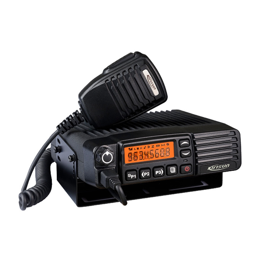
Page 6: Radio Overview
Connect the antenna and the power cable to the radio. button (programmable button) Install the microphone hanger at the position easy to use, with 4 LCD display screen For details, see LCD Display . 2 M4*16 self-tapping screws. (The microphone and its cable sho- 5 Volume Control knob -uld be fixed at the position not affecting safe driving.) To be used to adjust volume. -
Page 7: Basic Operation
3 Basic Operation Display Description 1.Startup: means the transmission of signal for the radio at the high power; Press the red POWER button for a long time (at least 1.5 seconds) to switch the radio on/off Call Received indicator. The radio receives a selective call/call alert. 2.Volume Press the MONITOR... -
Page 8: Programmable Button Function
Programmable Button Function Buttons Function Description 11.Key lock To toggle between locking/unlocking your radio can be programmed as keypad. one of the following functions. 12.Scan Start/end the scanning function of system. Buttons Function Description 13.Nuisance When one channel continually generated 0. -
Page 9: Radio Call
Buttons Function Description Buttons Function Description 3 key. state to quit such a state. Sends the DTMF/2Tone code assigned to call Press this button to trigger this function and the 21.Monitor/ 29.Call Button 4 4 key. CTCSS, DCS, 2Tone/DTMF signalling will be Call Cancel closed, so you can receive the signal that can't To enter the menu mode or make menu... -
Page 10: Call Alert
A.Press Menu Select/Enter button to enter the menu E.Press button to send the call. mode. F.After calling, press button to return the previous operation. B.Press button until RADIOCAL . C.Press button to select SEL CALL . D.Press button until the required call list appears. 6. -
Page 11: Utilities
Items Selectable Setups Functions B.Press button until RPTRTALK . C.Press button for selection. Squelch Level Change the squelch level of the SQL 0 ~ 9 SQL LEV D.Press button until REPEATE TALKRND . radio. E.Press button for confirmation. Transmission PWR LOW Select transmission power among Power 2. -
Page 12: Nuisance Delete
delete. During sweep, the red indicator will flicker. When the scan is G.Press button to complete operation you will s ee landed on, the indicator will stop flickering. SAVE (If you added a channel)or CHN DEL . 1.Enter the scan state through menu mode. H.Press button to return to the previous operation. -
Page 13: Gps Information View
Note: If the wired clone function is enabled, the radio will not quit after When the OST backup function is enabled, the radio retains entering the wired clone mode. To return to normal user mode, the the OST code of each channel even if the channel is changed user needs to restart the machine. -
Page 14: Major Specifications
Problem Solution Problem Solution E.The FM IC U101 is broken. Please D.The battery is out of power. Please charge change IC. or change it. E.CPU is broken, Please change the IC. A.The power-amplifier tube Q23/Q25 is A.The crystal X1 of phase lock loop is broken. broken, resulting in no power output. - Page 15 185mm*62mm*170mm Weight: machine only: 1450g; plus fixed bracket: 1690g 0678 We, Kirisun Electronics(Shenzhen) Co., Ltd. 6/F, Bldg. H-2, East Industrial Zone Of Overseas Chinese Town, Shenzhen 518053, China Declare on our sole responsibility that this equipment complies with...
Need help?
Do you have a question about the PT8200 and is the answer not in the manual?
Questions and answers