Table of Contents
Advertisement
Quick Links
Advertisement
Table of Contents

Subscribe to Our Youtube Channel
Related Manuals for Sanwa PC700


Summary of Contents for Sanwa PC700
- Page 1 PC700 DIGITAL MULTIMETER INSTRUCTION MANUAL...
-
Page 2: Table Of Contents
[ 7] AFTER-SALE SERVICE Overload Protection [ 2] APPLICATIONS AND FEATURES Warranty and Provision Applications Repair Features SANWA web site [ 3] Parts Identification [ 8] SPECIFICATIONS Multimeter and Test Leads General Specifications Display Measuring Range and Accuracy [ 4] DESCRIPTION OF FUNCTIONS... -
Page 3: 1] Safety Precautions
This instruction manual explains how to use your digital multimeter damaged. PC700. Before using, read through this manual to reduce the risk 2. Be sure to use the specified fuse. of fire , electric shock, and/or injury. And save it together with the Neither use unspecified fuse nor short-circuit the fuse holder. -
Page 4: Overload Protection
1-3 Overload Protection [ 2] APPLICATIONS AND FEATURES 2-1 Applications Measuring Function Max. Rated Input Overload Protection This instrument is a portable digital multimeter designed to terminal measure light electric circuits. The instrument offers not only 「 」 , 「 」 1000V dc/ac 1050V rms, 1450V peak measurements for small communication equipments, home electric appliances, output from a wall socket, and many batteries,... -
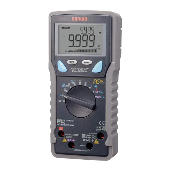
Page 5: 3] Parts Identification
How to detach the light shielding magnet cap [ 3] Parts Identification Light shielding magnet cap 3-1 Multimeter and Test Leads Light shielding magnet cap Optical communication unit connector LCD display ⇒ Range hold button Select button Turn the light shielding magnet cap counterclockwise to detach. Relative button Data hold button An application of the light shielding magnet cap... -
Page 6: Display
3-2 Display [ 4] DESCRIPTION OF FUNCTIONS ⑤ ⑥ ⑪ ⑩ ⑦ ⑧ ② 4-1 Power Switch/Function Selector Turn the switch to turn on/off the power and select a measuring function. All segments of the LCD display will be turned on for 1 seconds after power-on, and then the meter will be ready to use. -
Page 7: Low Battery Indication
4-2-2 How to disable the Auto Power Saving 「 」 ・ :[ µ ] ⇒ [ µ /µ ] ⇒ [ µ /Hz ] ⇒ [ µ ] ⇒ … Press the SELECT button while turning the meter power on. Release the SELECT button after is turned off. -
Page 8: Pc (Personal Computer) Interface
4-8 PC (Personal Computer) Interface 4-9 Test Leads Improper Connection Warning The instrument equips with an optical isolated interface port at the The meter beeps as well as displays “ InEr” to warn the user meter back for data communication. KB-USB7, dedicated USB against possible damage to the meter due to test leads improper optical communication unit (separately available), and PCLink7, connections to the... -
Page 9: 5] Measuring Procedures
[ 5] Measuring procedures START 5-1 Pre-operational Check WARNING Damaged 1. Do not use the instrument if the meter or test leads look Meter/Test leads damaged? damaged. 2. Make sure the test leads and the fuse are not broken. Looks OK CAUTION Make sure the low battery indicator is off after power-on. -
Page 10: Ac Voltage ( ) / Frequency (Hz) Measurement
「 」 (Max. rated input voltage: 1,000V dc/ac) / Hz Hz / • AC Voltage ( )/Frequency (Hz) Simultaneous Measurement WARNING 1. Do not apply any input signal exceeding the max. rated input voltage. 2. Do not switch the function selector while measuring. 3. - Page 11 「 」 Note: (Max. rated input voltage: 1,000V dc/ac) Hz input sensitivity varies automatically with a selected voltage ・ DC Voltage( ) measurement range. 9.999V range has the highest sensitivity and the 999.9V ・ DC Voltage( )/AC Voltage( ) simultaneous measurement range has the lowest.
-
Page 12: Duty Cycle ( D%) Measurement
「 」 (Max. rated input voltage: 10V dc/ac) ・ DC voltage (m ) measurement ・DC Voltage (m )/AC Voltage(m ) simultaneous measurement ・ Logic-level frequency ( ) measurement ・ Duty cycle ( D%) Measurement WARNING 1. Do not apply any input signal exceeding the max. rated input voltage. - Page 13 Note: ・ The display style of [m /m ], [ ], and [ D%] does not show the bar graph. ― 2 1 ― ― 2 2 ―...
- Page 14 「 」 (Max. rated input voltage: 600mV dc/ac) / Hz Hz / m ・ AC Voltage (m )/Frequency (Hz) Simultaneous Measurement WARNING 1. Do not apply any input signal exceeding the max. rated input voltage. 2. Do not switch the function selector while measuring. 3.
-
Page 15: Resistance (Ω) Measurement
「 」 (Do not apply any voltage or current.) Ω ・ Resistance (Ω) measurement WARNING Do not apply any voltage or current to the measuring terminals. CAUTION In the case of high resistance measurement, readings may be unstable due to external inductive influence. 1) What to measure ・... -
Page 16: Continuity Check ( )
「 」 (Do not apply any voltage or current.) ・ Continuity Check ( WARNING Do not apply any voltage or current to the measuring terminals. CAUTION In the case of high resistance measurement, readings may be unstable due to external inductive influence. 1) What to measure ・... -
Page 17: Capacitance( )Measurement, Diode
「 」 (Do not apply any voltage or current.) ・ Capacitance ( ) measurement ・ Diode ( ) test WARNING 1. Do not apply any voltage or current to the measuring terminals. 2. Measuring live circuit may damage the meter. 5-8-1 Capacitance ( ) measurement CAUTION... - Page 18 5-8-2 Diode ( ) test What to measure (Diode test): Judging the diode (Good or defective) Measuring procedure ① Connect the red plug of the test lead to measuring terminal and the black one to the COM terminal. ② Set the function selector to , then press the SELECT button to select the diode test.
-
Page 19: (Hz) Measurement
「 」 「 」 5-9-1 Current (mA/µA) measurement ・ DC current (m (m , m , µ , µ Max. rated input current 600mA dc/ac) ,µ , ) measurement ・ AC c ur r ent (m , µ )/ Fr eq uen c y(Hz) s i m ul t aneo u s 1) What to measure measurement ・... - Page 20 Note: Measuring Frequency (Hz) µ µ / µ Frequency range Range Input sensitivity(Sine wave) 600.0µA 60µA 6000µA 600µA 15.00Hz 〜 3.000kHz 60.00mA 40mA 600.0mA 60mA 5-9-2 Current (A) measurement ( , Max. rated input current AC 10A dc/ac ) 1) What to measure ・...
- Page 21 / Hz µ / Hz m / Hz Note: ・> 6A: Cool down more than 3 minutes after measuring 1 minute. < 6A Continuable Measuring Frequency (Hz) Frequency range range Input sensitivity (Sine wave) 6.000A 15.00Hz 〜 3.000kHz 10.00A ― 3 7 ― ―...
-
Page 22: Measurements With Separately Available Accessories
5-10 Measurements with Separately Available Accessories 5-10-1 Clamp probe: CL-20D (Max. measurable current 200A ac) WARNING 1) What to measure 50/60 Hz sine wave current such as consumption current of 1. Do not apply any input exceeding max. rated input for the home appliances, current of power supply equipments, and etc. - Page 23 5-10-2 Clamp probe: CL-22AD 5-10-3 DC Clamp probe: CL-33D (Max. measurable current 200A dc/ac) (Max. measurable current 300A dc) 1) What to measure 1) What to measure ACA: 50/60 Hz sine wave current such as consumption current Current of automotive electric circuits, consumption current of of home appliances, current of power supply equipments, DC equipments, etc.
-
Page 24: Simple Examination
To make temperature measurement, connect the temperature throughly to maintain the instrument. probe to the PC700 connected to the PC on which sanwa's 2. Calibrate and inspect the instrument at least once a year to software PC Link7 is installed and running. -
Page 25: Battery And Fuse Replacement
6-3 Battery and Fuse Replacement Rear case WARNING Battery door 1. Do not open the rear case with live measuring terminals to avoid Battery electric shock. Also, make sure the meter power is OFF , before Fuse 0.63A/500V φ 6.3× 32mm starting replacement. -
Page 26: 7] After-Sale Service
7-1 Warranty and Provision. 3) Repair after the warranty period has expired: Sanwa reserves the rig ht to insp ect all warranty claims to In some cases, repair and transportation cost may become determine the extent to which the warranty policy shall apply. This higher than the price of the product. -
Page 27: 8] Specifications
Auto Power [ 8] SPECIFICATIONS Approx. 30 minutes after the last operation Saving 8-1 General Specifications IEC61010-1:2001 IEC61010-031:2008 Operation Category II for 1000V ac and dc Delta-sigma modulation method Safety Category III for 600V ac and dc 9,999 counts: Compliances Category II for 500V ac and dc mAµA DCV, ACV, Logic-Level Frequency(Hz),... -
Page 28: Measuring Range And Accuracy
AC Voltage ACV 8-2 Measuring Range and Accuracy Accuracy: ± (% rdg + dgt) AC voltage (ACV)/ Frequency (Hz) for dual display rdg: reading, dgt: least significant digit Range Accuracy Temperature: 23 ℃ ± 5 ℃ , Humidity: < 75% R.H. 50Hz 〜... - Page 29 DC/AC Voltage (DC/AC V) for dual display DC current (DCA) Range Accuracy Range Accuracy Input resistance* * 50Hz 〜 60Hz 600.0µA Approx. 83 Ω 60.00mV, 600.0mV 6000µA ± (0.7% rdg + 6dgt) 9.999V, 99.99V, 999.9 60.00mA ± (0.2% rdg + 4dgt) Approx.
- Page 30 Resistance (Ω) Capacitance Range Accuracy Range Accuracy* ± (0.8% rdg + 3dgt) 600.0Ω, 6.000kΩ, 60.00nF, 600.0nF* * * 0.1% rdg + 3dgt ± (1.0% rdg + 3dgt) 60.00kΩ, 600.0kΩ 6.000µF ± (2.0% rdg + 3dgt) 6.000MΩ 0.4% rdg + 3dgt 60.00µF ±...
- Page 31 本社 = 東京都千代⽥区外神⽥2-4-4・電波ビル 郵便番号 = 101-0021・電話 = 東京 (03) 3253-4871㈹ ⼤阪営業所 = ⼤阪市浪速区恵美須⻄2 -7 -2 郵便番号 = 556-0003・電話 = ⼤阪 (06) 6631-7361㈹ SANWA ELECTRIC INSTRUMENT CO.,LTD. Dempa Bldg., 4-4 Sotokanda2-Chome Chiyoda-Ku,Tokyo,Japan This manual emplys soy ink. 02-1109 5008 6010...
Need help?
Do you have a question about the PC700 and is the answer not in the manual?
Questions and answers