Table of Contents
Advertisement
Quick Links
Advertisement
Table of Contents

Subscribe to Our Youtube Channel
Related Manuals for Sanwa PC773


Summary of Contents for Sanwa PC773
- Page 1 PC773 DIGITAL MULTIMETER 取扱説明書 INSTRUCTION MANUAL...
- Page 3 目 次 【1】安全に関する項目∼ご使用の前に必ずお読みください。∼ 1 − 01 警告マークなどの記号説明 ………………………… 001 1 − 02 安全使用のための警告文 …………………………… 001 1 − 03 過負荷保護入力値 …………………………………… 002 【2】用途と特長 2 − 01 用 途 ………………………………………………… 003 2 − 02 特 長 ………………………………………………… 003 【3】各部の名称 3 − 01 本体 …………………………………………………… 004 3 − 02 テストリード ………………………………………… 004 3 − 03 表示器 ………………………………………………… 005 【4】機能説明...
- Page 4 【1】安全に関する項目∼ご使用の前に必ずお読みください 。 ∼ このたびはデジタルマルチメータ PC773 型をお買い上げいただ き、誠にありがとうございます。 ご使用前にはこの取扱説明書をよくお読みいただき、正しく安全 にご使用ください。そして常にご覧いただけるように製品と一緒に して大切に保管してください。 本書で指定していない方法で使用すると、本製品の保護機能が損 なわれることがあります。 ● ● ● けど や や ● ● 電 などの事故防止のため、必ずお守りください。 感 1-1 警告マークなどの記号説明 本器および『取扱説明書』に使用されている記号と意味について :安全に使用するための特に重要な事項を示します。 ・警告文はやけどや感電などの人身事故を防止するためのものです。 ・注意文は本器を壊すおそれのあるお取り扱いについての注意 文です。 :高電圧注意 :グランド :直流 (DC) :周波数 :交流 (AC)...
- Page 5 16. 本体またはテストリードが傷んでいたり、壊れていたりして いる場合は使用しないこと。 17. ケースまたは電池ふたを外した状態では使用しないこと。 18. ヒューズは必ず指定定格および仕様のものを使用すること。 19. 測定中はテストリードのつばよりテストピン側を持たないこと。 10. 測定する場合は最初に接地側 ( テストリードの黒 ) を接続し、 離す場合は最後に接地側を離すこと。 11. 測定中は他のファンクションまたは他のレンジに切り換えた り、プラグを他の端子へ差し換えたりしないこと。 12. 測定前には、 ファンクションおよびレンジ確認を確実に行うこと。 13. 本器または手が水等でぬれた状態での使用はしないこと。 14. テストリードは指定タイプのものを使用すること。 15. 電池交換およびヒューズ交換を除く修理 ・ 改造は行わないこと。 16. 年1回以上の点検は必ず行うこと。 17. 屋内で使用すること。 注 意 トランスや大電流路など強磁界の発生している近く、無線機な ど電磁波の発生している近く、または帯電しているものの近く では正常な測定ができない場合があります。 1-3 過負荷保護入力値 各ファンクション入力端子の最大定格入力値および過負荷保護を定めています。 ファンクション...
- Page 6 【2】用途と特長 2-1 用 途 本器は CAT. Ⅱ 1000 V、CAT. Ⅲ 600 V 範囲内の測定用に設計 されたデジタルマルチメータです。 2-2 特 長 ・ IEC61010-1 に準拠した安全設計で、電流端子にヒューズによる保護 およびセーフティーキャップ付き ・ 11000 カウントフルスケール表示 ・ 交流(AC)は真の実効値測定 ・ 導通チェックは、ブザー音と赤色 LED ランプ点灯で確認 ・ 数値が大きく見易い表示器 ・ 周波数測定および静電容量測定機能付 ・ 手に持ちやすいデザイン ・ 本体にテストプローブを固定可能 ・ 二重成形で、外側は弾力性のあるエラストマー素材を使用 ・ 抵抗測定 最小分解能 0.01 Ω ・...
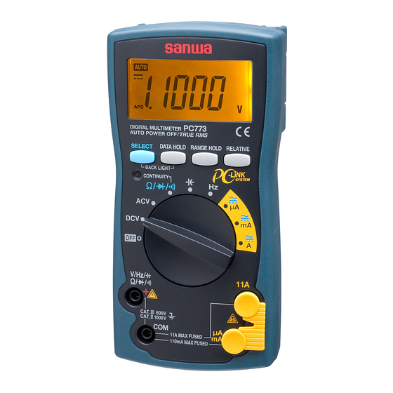
- Page 7 【3】各部の名称 3-1 本体 USB 光通信ユニッ ト 接続部 レンジホールド リラティブボタン 電池ホルダ ボタン 液晶表示部 データホールド (バックライトボタン) セレクトボタン (バックライトボタン) 導通ランプ 電源スイッチ兼 ファンクションスイ ッチ 測定端子 COM (共通) 端子 セーフティー 11 A 測定端子 測定端子 キャップ スタンド 3-2 テストリード ・着脱式テストピンキャップ装着時 :CAT.Ⅲ 600 V ・着脱式テストピンキャップ未装着時:CAT.Ⅱ 1000 V 着脱式テス ト ピン キャ...
- Page 8 3-3 表示器 ① 数値表示 ② オートパワーオフ動作表示 ③ リラティブモード動作表示 ④ 数値データのマイナス極性表示 ⑤ 交流測定ファンクション動作表示 ⑥ 直流測定ファンクション動作表示 ⑦ オートレンジモード動作表示 ⑧ 光データ出力動作表示 ⑨ ダイオードテストファンクション動作表示 ⑩ 導通チェックファンクション動作表示 ⑪ データホールドモード動作表示 ⑫ 本器では使用しません ⑬ 電池消耗警告表示 ⑭ 測定単位表示 − 5 −...
- Page 9 【4】機能説明 4-1 電源スイッチ兼ファンクションスイッチ このスイッチを回して電源の ON/OFF および各測定ファンクショ ンを切り換えます。 4-2 測定機能選択: ボタンを押す (→) と、 フ ァンクシ ョ ンは以下のように切り換わります。 ・ ポジション : 抵抗測定 ( ) → 導通チェック ( ) → ダイオー ドテスト( )→ 抵抗測定( ) ・ μ Aポジション:直流電流 ( ) → 交流電流 ( ) → 直流電流 ( ) ・...
- Page 10 4-5 レンジホールド: ボタンを押すとマニュアルモードとなり、 レンジが固定さ れます。 (表示器から が消えます。 )マニュアルモードになると、 このボタンを押すたびにレンジが移動しますので、表示器の単位と 小数点の位置を確認しながら適正レンジを選択してください。オー トレンジに復帰させる場合は、このボタンを 1 秒以上押してくださ い。 (表示器の が点灯します。 ) 4-6 リラティブ測定(相対値測定) : ボタンを押すと、 と が点灯し、 押した時点の入力値 を基準とした値を表示します。 また、 ボタンを押した時点の基準値を確認したいときは再度ボ タンを押す(1秒未満)と と が点滅し、基準値を表示します。 もう一度ボタンを押す(1秒未満)とリラティブ測定に戻ります。 リラティブ測定を解除にするにはボタンを1秒以上再度押してください。 例)DC 6.000 V 入力時にボタンを押した後の表示 実際の入力値 表示器の数値 DC 6.000 V DC 0.000 V DC 10.00 V DC 4.000 V...
- Page 11 ・ オートパワーオフ状態でも通常使用時の 1/100 程度の電流を消 費しています。 長時間ご使用にならない場合は必ず電源スイッチを OFF してください。 4-8 電池消耗警告表示 内蔵電池が消耗し電池電圧が約 2.3 V 以下になったときには、表 示器に マークが表示されます。このマークが点滅または点灯した ときには、新しい電池 (2 本共に) と交換してください。 4-9 交流検波方式 本器は実効値方式で、交流の大きさを直流と同じ仕事量として表 します。TRUE RMS (Root Mean Square) 回路により正弦波や方形波、 三角波など非正弦波の実効値測定ができます。 4-10 クレストファクタ(波高率) CF(クレストファクタ)は信号のピーク値をその信号の実効値で割っ た値で表します。正弦波や三角波等最も一般的な波形は相対的にクレ ストファクタは低くなっています。また、デューティーサイクルの低 いパルス列に類似した波形では高いクレストファクタとなります。代 表的な各波形の電圧、クレストファクタは表を参考にしてください。 なお、クレストファクタ数は 3 以下で測定してください。 ピーク値 実効値 平均値...
- Page 12 4-11 パソコンとの接続 本体は USB インターフェイスを使用した DMM データ通信が可 能です。 本体に別売 USB 光通信ユニット (KB-USB773) をセットし、パ ソコンに接続すると本体側からデータが出力されます。別売の PC リンクソフト(PC Link7)をお求めの上、ご利用ください。 詳細は、別売 PC リンクソフト (PC Link7) のヘルプをご覧くだ さい。 〈ケーブルと本体の接続〉 ① 本体リアケース部の遮光ゴムキャップを外します。 ② USB 光通信ユニットを本体に接続します。 ③ USB コネクタをパソコンに接続します。 ④ USB 光通信ユニットを取り外す際は、図のように PUSH 文字 部分を押しながら抜きます。 備考 : PC Link 使用中はオートパワーオフが機能しません。...
- Page 13 【5】測定方法 警 告 1. 各ファンクションの最大定格入力を超えた入力信号を加えないこと。 2. 測定中はファンクションスイッチを切り換えないこと。 3. 測定中はテストリードのつばよりテストピン側を持たないこと。 4. 測定後は被測定物からテストリードを離し、ファンクション スイッチを 位置に戻すこと。 5-1 始業点検 注 意 1. 電源スイッチを ON したとき、電池消耗警告表示が点滅また は点灯していないことを確認すること。点滅または点灯して いるときは、新しい電池と交換すること。 2. 本体およびテストリードが傷んでいたり、壊れていたりして いる場合は使用しないこと。 3. テストリードおよびヒューズが切れていないことを確認すること。 安全のため、 必ず始業点検を行ってください。 ( 導通チェックによる点検) 確 認 ※表示器に何も表示が出ない場合は、 電池の全消耗が考えられます。 − 10 −...
- Page 14 5-2 直流電圧測定( ) ファンクション 最大定格入力 レンジ 110.00 mV, 1.1000 V, 11.000 V, DC 1000 V 110.00 V, 1000.0 V DCV 測定例 備考: ・ DC 110 mV レンジは ボタンで選択します。 このレンジは高入力インピーダンスのため、テストリード開放 時に表示が変動する場合や OL 表示をする場合がありますが故 障ではありません。 − 11 −...
- Page 15 5-3 交流電圧測定( ) ファンクション 最大定格入力 レンジ 110.00 mV, 1.1000 V, 11.000 V, AC 1000 V 110.00 V, 1000.0 V ACV 測定例 備考: ・ AC 110 mV レンジは ボタンで選択します。 ・ テストリード開放時に表示が変動する場合や OL 表示をする場 合がありますが故障ではありません。 ・ 本器の交流(AC)測定は、 AC 結合の真の実効値測定方式です。 確度保証は以下の範囲になります。 周波数範囲:110 mV レンジ 45 Hz ∼ 100 Hz 1.1 V レンジ 45 Hz ∼...
- Page 16 5-4 抵抗測定 ( ) 、導通チェック ( ) 、ダイオードテスト ( ) 警 告 測定端子には外部から電圧を絶対に加えないこと。 5-4-1 抵抗測定 ( ) ファンクション 最大定格入力 レンジ 110.00 Ω, 1.1000 kΩ, 110 MΩ 11.000 kΩ, 110.00 kΩ, 1.1000 MΩ, 11.000 MΩ, 110.0 MΩ 備考: 測定に際しノイズの影響を受ける場 抵抗器 合は、 被測定物を COM 電位でシー ルドしてください。...
- Page 17 5-4-3 ダイオードテスト ( ) 順方向テスト 逆方向テスト 抵抗測定 導通チェック ダイオー ドテス ト 切替 カソード アノード 備考: 測定端子間の開 放電圧は電源電 良品例:OL 表示 良品例:順方向電圧 不良例:他の表示 圧 − 約 0.2 V と 降下表示 不良例:0.000 V 表示 なります。 OL 表示 5-5 静電容量測定( ) 警 告 測定端子には外部から電圧を絶対に加えないこと。 注 意 1. コンデンサ内の電荷は測定前に放電すること。 2.
- Page 18 5-6 周波数測定 ( ) 注 意 測定禁止 対接地間の周波数測定は、漏電ブレーカー 等が動作する可能性がありますので、絶対 に行わないでください。 ファンクション 最大定格入力 レンジ 1.1 MHz 110.0 Hz, 1100 Hz, 11.000 kHz, 110.00 kHz, 1.1000 MHz (≦1000 Vrms) ・ フ ァ ン ク シ ョ ンは入力抵抗が 約1 kΩと非常に低いので、 測定時には多くの電流が流 れます。電流容量の小さい 回路や装置の測定は絶対に 行わないでください。 ・ 測定する周波数にノイズが 含まれている場合、測定値...
- Page 19 5-7 電流測定( ) 警 告 1. 測定端子には電圧を絶対に加えないこと。 2. 最大定格電流を超える入力は加えないこと。 3. 必ず負荷を通して本器が直列に接続されること。 正しい測定方法 誤った測定方法 注 意 内蔵ヒューズが切れていないかご確認ください。 ファンクション 最大定格入力 レンジ DC/AC 110 μA 110.00 μA, 1100.0 μA DC/AC 110 mA 11.000 mA, 110.00 mA DC/AC 11 A 11.000 A 備考: ・ 電流測定では、電流レンジの内 DCAとACA 部抵抗が直列に入りこの分だけ 切替...
- Page 20 ・ 測定 ファンクション 入力端子 使用内蔵ヒューズ 315 mA/1000 Vヒューズ と 遮断容量30 kA 測定 ファンクション 入力端子 使用内蔵ヒューズ 12 A/1000 Vヒューズ と 遮断容量30 kA 備考: 入力信号を加えても表示がほとんど変化しない場合や、予想した 電流値より著しく小さい値の場合は、入力端子やファンクション スイッチの位置が違っていたり、ヒューズが遮断している可能性 がありますので確認を行ってください。 − 17 −...
- Page 21 5-8 別売品による測定 警 告 1. 使用する製品の最大定格入力値を超える入力信号は印加しな いこと。 2. 測定中は他のファンクションに切り換えないこと。 5-8-1 直流高電圧プローブ (HV-60) による測定 最大測定電圧 DC 30 kV 警 告 1. このプローブは微小電流回路測定用です。送電線などの強電 用には使用しないこと。 2. プローブの最大測定電圧(DC 30 kV)を超える電圧は印加し ないこと。 3. 測定中は他のファンクションに切り換えないこと。 4. 測定中はプローブのつばより測定ピン側を持たないこと。 1) 測定対象:テレビのブラウン管などのアノード電圧、フォー カス用高電圧など高インピーダンス回路の電圧測定 2) 測定レンジ:DC 1000 V レンジを使用(マニュアルモードに て設定) 3) 測定方法 ① 高 圧 プ ロ ー ブ の 赤 プ ラ グ を V 入 力 端 子 に、 黒 プ ラ グ を COM 入力端子に差し込みます。...
- Page 22 ④ ⑤ ② ③ Anode ① 5-8-2 交流電流プローブ (CL-20D) による測定 最大測定電流 AC 200 A 1) 測定対象:家電機器の消費電流や電源設備など、50 ∼ 60 Hz の正弦波交流の測定に用います。 2) 測定レンジ:20 A、200 A の 2 レンジ 3) 測定方法 ① 電流プローブの赤プラグをV入力端子に、黒プラグをCOM 入力端子に差し込みます。 ② ファンクションスイッチをACVに設定し、レンジホールドスイッ チで11 Vレンジにします。 ③ 電流プローブのレンジ設定つまみを20 Aまたは200 Aレン ジに合わせます。 ④ 電流プローブの鉄心を開き、 被測定導体をクランプします。 ⑤...
- Page 23 5-8-3 直流 ・ 交流電流プローブ (CL-22AD) による測定 最大測定電流 DC/AC 200 A 1) 測定対象 ACA : 家電機器の消費電流や電源設備など、50 ∼ 60 Hz の 正弦波交流の測定に用います。 DCA : 自動車の電装回路の電流や直流機器の消費電流を測り ます。 2) 測定レンジ DC 20 A/200 A,AC 20/200 Aの各2レンジ 3) 測定方法 ① 電流プローブの赤プラグをV端子に、黒プラグをCOM端子 に差し込みます。 ② ファンクションスイッチを直流電流 (D C A) ならD C Vに設定 し、レンジホールドスイッチで1.1 Vレンジにします。...
- Page 24 5-8-4 直流電流プローブ (CL33DC) による測定 最大測定電流 DC 300 A 1) 測定対象:自動車の電装回路の電流や直流機器の消費電流を 測ります。 2) 測定レンジ:30 A, 300 Aの 2レンジ 3) 測定方法 ① 電 流 プ ロ ー ブ の 赤 プ ラ グ を V 入 力 端 子 に、 黒 プ ラ グ を COM 入力端子に差し込みます。...
- Page 25 5-8-5 温度プローブ(T-300PC)による測定 1) 測定対象:温度を測る場合に用います。 ※ 単体での測定は出来ません。 測定の際は sanwa 製ソフトウェ ア PC Link7 がインストールされ、そのソフトウェアが起 動しているパソコンにつながった PC773 と接続してくださ い。 2) 測定範囲:-50∼300 ℃ ※DMMは11 kΩレンジを使用 3) 測定方法 ① センサプローブの赤プラグを Ω 端子に、 黒色プラグを COM 端子に差し込みます。 ② ファンクションスイッチを に設定し、 ボ タンで Ω を選択します。 ③ ボタンで 11 kΩ に設定します。...
- Page 26 【6】保守管理について 警 告 1. この項目は安全上重要です。 本説明書をよく理解した上で管理を行ってください。 2. 安全と確度維持のために1年に1回以上は校正、 点検を行ってください。 6-1 保守点検 1)外観:落下などにより、外観が壊れていないか? 2)テストリード: ・テストリードから芯線が露出していないか? ・入力端子にプラグを差し込んだときに緩みはないか? 以上の項目に該当するものはそのまま使用せず、修理を依頼 してください。 6-2 校正・点検 詳細については三和電気計器 (株) までお問い合わせください。 項目 7-3 を参照。 6-3 保管について 注 意 1. 本体は揮発性溶剤に弱いため、シンナーやアルコールなどで 拭かないこと。 2. 本体は熱に弱いため、高熱を発するものの近くに置かないこと。 3. 振動の多い場所や落下のおそれのある場所に保管しないこと。 4. 直射日光や高熱、低温、多湿、結露のある場所での保管は避 けること。 5. 長期間使用しない場合は内蔵電池を必ず抜いておくこと。 6-4 電池、ヒューズの交換 出荷時の電池について 工場出荷時に組み込まれている電池はモニター用電池ですので 電池寿命が新品電池より短い場合があります。 モニター用電池とは製品の機能や性能をチェックするための電...
- Page 27 警 告 1. 感電のおそれがあるため、測定端子に入力が加わった状態で リヤケースを外さないこと。また、ファンクションスイッチが OFF になっていることを確認し作業を行うこと。 2. 交換用ヒューズは同定格のものを使用すること。ヒューズの 代用品を用いたり、短絡したりすることは絶対にしないこと。 6-4-1 電池交換 ① 電池ホルダ固定ネジをプラスドライバーで外します。 ② 電池ホルダ内の電池を 2 本共に新品と交換します。 (電池極性にご注意ください。 ) ③ 電池ホルダ固定ネジを元どおりネジ止めします。 使用電池 単 3 電 池 ( R 6 ) 2 本 6-4-2 ヒューズ交換 ① 本体リアケースのネジをドライバーで外します。 ② 内部にあるヒューズを取り出し、新しいヒューズと交換します。 ③ リヤケースを元どおりネジ止めします。 ヒューズ 使用ヒューズ定格 315 mA/1000 V (φ6.35×32 mm、遮断容量...
- Page 28 【7】アフターサービスについて 7-1 保証期間について 本製品の保証期間は、お買い上げの日より 3 年間です。 ただし、日本国内で購入し日本国内でご使用いただく場合に 限ります。また、製品本体の確度および許容差は 1 年保証、 製品付属の電池、ヒューズ、テストリード等は保証対象外とさ せていただきます。 7-2 修理について 1)修理依頼の前にもう一度次の項目をご確認ください。 ・内蔵電池の容量と電池装着時の極性をチェック。 ・内蔵ヒューズとテストリードの断線をチェック。 2)保証期間中の修理:保証書の記載内容によって修理させてい ただきます。 3)保証期間経過後の修理 修理および輸送費用が製品価格より高くなる場合もあります ので、事前にお問い合わせください。補修用性能部品の最低 保有期間は、製造打切り後 6 年間です。この保有期間を修理 可能期間とさせていただきます。ただし、性能部品が製造中 止などにより入手不可能になった場合は、保有期間が短くな る場合もあります。 4)修理品の送り先 製品(本体およびテストリード等の付属品を含む)の安全輸 送のため、製品の 5 倍以上の容積の箱に入れ、十分なクッショ ンを詰め、 箱の表面に「修理品在中」と明記して送りください。 輸送にかかる往復の送料は、お客様のご負担とさせていただ きます。 [送り先]三和電気計器株式会社・羽村工場サービス課 〒 205-0023 東京都羽村市神明台 4-7-15 TEL(042)...
- Page 29 30 kA ¥510 ( 税込) ¥120 (4 本迄) 7-3 お問い合わせ 三和電気計器株式会社 本 社 :TEL(03) 3253-4871 / FAX(03) 3251-7022 大阪営業所 :TEL(06) 6631-7361 / FAX(06) 6644-3249 お客様計測相談室: 0120-51-3930 受付時間 9:30 ∼ 12:00 13:00 ∼ 17:00 (土日祭日を除く) ホ ー ム ペ ー ジ:http://www.sanwa-meter.co.jp − 26 −...
- Page 30 【8】仕 様 8-1 一般仕様 動作方式 二重積分方式 交流検波方式 真の実効値方式 液晶表示器 11000 カウント サンプルレート 約 4 回 / 秒( ) 約 20 回 / 秒( ) 約 4 回 / 秒( 11μF レンジ以下) 約 2 回 / 秒( 110μF レンジ) 約 1 回 / 秒( 1.1 mF レンジ)...
- Page 31 付属品 テストリード(TL-25) 、取扱説明書 USB 光通信ユニット:KB-USB773 PC Link ソフトウェア:PC Link7 アリゲータクリップ:CL-11, CL-15, TL-8IC 別売品 高圧プローブ:HV-60 ク ランププローブ:CL-22AD, CL-33DC, CL-20D 携帯ケース : C-77, C-77H 8-2 測定範囲および確度 温度 :23±5 ℃ 湿度:80 %R.H. 以下 (結露のないこと) 、 電源電圧 2.4 V 以上 rdg(reading):読み取り値 dgt(digit):最終桁のカウント数 DCV直流電圧 レンジ 確 度 入力抵抗 備 考...
- Page 32 導通チェック 導通ブザー発音及び導通ランプ点灯範囲:30 Ω 未満で発音および点灯。 ダイオードテスト 開放電圧:電源電圧−約 0.2 V となります。 静電容量測定 レ ン ジ 確 度 備 考 11.000 nF ±(4.0 %rdg+30dgt) 110.00 nF ±(2.0 %rdg+20dgt) ・11 nFおよび110 nFレンジでは表示され 1.1000 μF ている値をREL機能によりキャンセル 11.000 μF ±(3.0 %rdg+10dgt) した後の確度 110.00 μF ・フィルムコンデンサなど漏れ電流の少...
- Page 33 ACA交流電流測定 レンジ 確 度 入力抵抗 備 考 ・確度保証周波数範囲: 110.00 μA 45 Hz∼1 kHz ± (0.9 %rdg+20dgt) 約1 kΩ 1100.0 μA クレストファクタ (CF) 範囲: 3以下 11.000 mA レンジ範囲: ± (1.1 %rdg+20dgt) 約10 Ω 110.00 mA 各レンジの5 %∼100 % ・入力抵抗は、ヒューズ抵 11.000 A ± (0.9 %rdg+40dgt) 約0.01 Ω...
- Page 34 保証書 ご氏名 PC773 型 名 様 製造 No. ご住所 この製品は厳密なる品質管理を経てお 〒 届けするものです。 本保証書は所定項目をご記入の上保管 していただき、アフターサービスの際 ご提出ください。 ※ 本保証書は再発行はいたしませんの で大切に保管してください。 保証期間 本社 = 東京都千代田区外神田2−4−4 ・ 電波ビル ご購入日 年 月より 3 年間 郵便番号 = 101-0021・電話 = 東京 (03) 3253−4871(代) 保証規定 保証期間中に正常な使用状態のもとで、万一故障が発生した場合には無償で修理いたします。 ただし下記事項に該当する場合は無償修理の対象から除外いたします。 記 1. 取扱説明書と異なる不適当な取扱いまたは使用による故障...
- Page 35 PC773 DIGITAL MULTIMETER INSTRUCTION MANUAL...
-
Page 36: Table Of Contents
Calibration and Inspection ……………………………… 025 Storage …………………………………………………… 025 Battery and Fuse Replacement ………………………… 025 【7】AFTER-SALE SERVICE Warranty and Provision …………………………………… 027 Repair ……………………………………………………… 027 SANWA web site ………………………………………… 028 【8】SPECIFICATIONS General Specifications …………………………………… 029 Measuring Range and Accuracy ………………………… 030... -
Page 37: Safety Precautions - Before Use, Read The Following Safety Precautions
*Before use, read the following safety precautions. This instruction manual explains how to use your digital multimeter PC773. Before use, please read this manual thoroughly to ensure correct and safe use. After reading it, keep it together with the product for reference to it when necessary. - Page 38 4. Never use the meter for measuring voltages of lines connected to equipment (e.g. motors) that generates induced or surge voltage since it may exceed the maximum allowable overload input. 05. Never use the meter near equipment which generates strong electromagnetic waves or is charged.
-
Page 39: Overload Protection Input
1-3 Overload Protection Input The maximum rated input value and overload protection have been established for the input terminals of each function. Function Input Terminal Max. Rated Input Value Max. Overload Protection Input Value ・ ・ DC/AC 1000 V DC/AC 1000 V Do not input a ・... -
Page 40: Applications And Features
[2] APPLICATIONS AND FEATURES 2-1 Applications This is a digital multimeter designed for measurement in the ranges of CAT. II 1000 V and CAT. III 600 V. This meter is useful for measuring / analyzing circuits of small communication devices, home electric appliances and batteries within the CAT. -
Page 41: Names Of Component Units
[3] NAMES OF COMPONENT UNITS USB optical communication unit connector 3-1 Multimeter Relative button Battery holder Range hold button LCD display Data hold button (Backlight button) Select button (Backlight button) Continuity lamp Power switch & function switch measuring terminal COM (common) terminal 11 A measuring Safety cap terminal... -
Page 42: Display
3-3 Display ① Numeral data display ② Auto power off display ③ Relative mode display ④ Minus polarity display for numeral data ⑤ AC measurement function display ⑥ DC measurement function display ⑦ Auto range mode display ⑧ Optical data output display ⑨... -
Page 43: Description Of Functions
[4] DESCRIPTION OF FUNCTIONS 4-1 Power Switch & Function Switch Turn this switch to turn on and off the power and select a measuring function. SELECT 4-2 Measuring Function Selection: When the button is pressed, the functions change as follows: position: Resistance measurement ( ) →... -
Page 44: Range Hold
4-5 Range Hold: When the button is pressed, the meter is set in the manual mode and the range is fixed. (“ ” disappears from the display.) In the manual mode, each time this button is pressed, the range changes. While checking the unit and decimal point on the display, select the best range. -
Page 45: Battery Low Warning Indication
To return from the Auto Power Off mode, press one of the four push buttons. To cancel the Auto Power Off function, turn the function switch to a position other than OFF while holding the button pressed. “APO” on the display is turned off when the Auto Power Off function is canceled. -
Page 46: Connection With Pc
Root Mean Average Crest Form 0 to PEAK Square Value Value Factor Factor Input Waveform Vrms Vavg Vp/Vrms Vrms/Vavg π 2 Vp − − − √ Sinusoidal √ π √ π 2π wave =1.414 =1.111 =0.637 Vp =0.707 Vp Square wave 2π... - Page 47 ③ Connect the USB connector to a PC. ④ To disconnect the USB optical communication unit, pull it while holding down the section inscribed with "PUSH" as shown in the figure. Remarks: The Auto Power Off function is defeated during the PC Link operation. The Auto Power Off function is also defeated if power enters the communication block of the multimeter.
-
Page 48: Measuring Procedure
[5] MEASURING PROCEDURE WARNING 1. Do not apply an input signal exceeding the maximum rated input of each function. 2. During measurement, do not change the function switch. 3. During measurement, do not touch the test pin side of the flange of the test lead. -
Page 49: Dc Voltage Measurement
5-2 DC Voltage Measurement ( Function Max. Rated Input Range 110.00 mV, 1.1000 V, 11.000 V, DC 1000 V 110.00 V, 1000.0 V DCV measurement example Remarks: The DC 110 mV range can be selected with the button. Since this range is a high-input impedance, display may fluctuate or show “OL”... -
Page 50: Ac Voltage Measurement
5-3 AC Voltage Measurement ( Function Max. Rated Input Range 110.00 mV, 1.1000 V, 11.000 V, AC 1000 V 110.00 V, 1000.0 V ACV measurement example Remarks: The AC 110 mV range can be selected with the button. The display may fluctuate or show “OL” when the test leads are released. -
Page 51: Resistance Measurement ( ), Continuity Check ( )
5-4 Resistance Measurement ( ), Continuity Check ( ) Diode Test ( ) WARNING Never apply a voltage to the measuring terminals. 5-4-1 Resistance measurement ( ) Function Max. Rated Input Range 110.00 , 1.1000 k , 11.000 k , 110 M 110.00 k , 1.1000 M , 11.000 M , 110.0 M... -
Page 52: Capacitance Measurement ( )
5-4-3 Diode test ( ) Forward Reverse direction test direction test Resistance measurement Continuity check Diode test Selection Remarks: Cathode Anode The open voltage between the measuring terminals Good: OL shown Good: Forward voltage is equal to: Power Bad: Other indication drop shown supply voltage –... -
Page 53: Frequency Measurement (Hz)
5-6 Frequency Measurement ( ) CAUTION Measurement prohibited Never use the meter for measuring frequencies to ground as the earth leakage breaker may trip. Function Max. Rated Input Range 1.1 MHz 110.0 Hz, 1100 Hz, 11.000 kHz, 1000 Vrms) 110.00 kHz, 1.1000 MHz ≦... -
Page 54: Current Measurement
5-7 Current Measurement ( WARNING 1. Never apply a voltage to the measuring terminals. 2. Never apply an input exceeding the maximum rated current. 3. Be sure to connect the meter in series via a load. Correct measuring method Wrong measuring method Power supply Load CAUTION... - Page 55 · measurement Function Input Terminal Built-in Fuse 315 mA/1000 V Fuse Breaking capacity 30 kA measurement Function Input Terminal Built-in Fuse 12 A/1000 V Fuse Breaking capacity 30 kA Remarks: If the indication changes little when an input signal is applied or a current value which is significantly smaller than the expected value is indicated, possible causes are the input terminals, incorrect setting of the function switch, or blown fuse.
-
Page 56: Measurements Using Optional Products
5-8 Measurements Using Optional Products WARNING 1. Never apply an input signal exceeding the maximum rated input value of the optional product. 2. Do not switch the function while measuring. 5-8-1 Measurement Using a DC High-Voltage Probe (HV-60) Max. measuring voltage: 30 kV DC WARNING 1. - Page 57 ④ ⑤ ② ③ Anode ① 5-8-2 Measurement Using an AC Clamp Probe (CL-20D) Max. measuring current: 200 A AC 1) Applications: Sine-wave current of 50 to 60 Hz AC, such as the current consumption of a home appliance or a power supply. 2) Measuring ranges: Two ranges including 20 A and 200 A.
- Page 58 ⑤ ② ④ ③ ⑥ ① 5-8-3 Measurement Using an AC/DC Clamp Probe (CL-22AD) Max. measuring current: 200 A AC/DC 1) Applications: ACA: Sine-wave current of 50 to 60 Hz AC, such as the current consumption of a home appliance or a power supply. DCA: Current of the electric circuit of an automobile or the current consumption of a DC device.
- Page 59 ④ Open the clamp jaws of the clamp probe and clamp the measuring wire. ⑤ In the 20 A range of the clamp probe, multiply the display reading by 100, and in the 200 A range, multiply the display reading in 1000. ⑥...
- Page 60 * Measurement cannot be performed by this probe alone. Connect it to the meter first. Then connect the meter to a PC that the Sanwa PC Link7 software is installed. 2) Measuring ranges Range of -50 ˚C to 300 ˚C * Use 11 k range.
-
Page 61: Maintenance
Is the plug when inserted to the input terminal not loose? If any of the above problems exists, stop using the meter and request for repair. 6-2 Calibration and Inspection For more information, please contact Sanwa’s authorized agent / distribute service provider, listed in our website. See section 7-3. - Page 62 WARNING 1. To avoid electric shock, do not remove the rear case with an input being applied to the measuring terminals. Also, before starting replacement, make sure the power of the meter is OFF. 2. Be sure to use the replacement fuse of the same rating. Never use a substitute for the fuse nor short the meter.
-
Page 63: After-Sale Service
(1) year from the date of purchase. This warranty policy is valid within the country of purchase only, and applied only to the product purchased from Sanwa authorized agent or distributor. Sanwa reserves the right to inspect all warranty claims to determine the extent to which the warranty policy shall apply. -
Page 64: Sanwa Web Site
Please contact Sanwa authorized agent / distributor / service provider, listed in our website, in your country with above information. An instrument sent to Sanwa / agent / distributor without above information will be returned to the customer. Note: 1) Prior to requesting repair, please check the following: Capacity of the built-in battery, polarity of installation and discontinuity of the test leads. -
Page 65: Specifications
[8] SPECIFICATIONS 8-1 General Specifications Operation method Double integration AC measuring method True RMS value method 11000 count Sampling rate Approx. 4 times/sec. ( Approx. 20 times/sec. ( Approx. 4 times/sec. ( : 11 μF or lower range) Approx. 2 times/sec. ( : 110 μF range) Approx. -
Page 66: Measuring Range And Accuracy
EMC Directive IEC61326 Dimensions 166( ) x 82( ) x 44( ) mm, projections not included. Mass Approx. 360 grams (batteries included) Standard Test leads (TL-25), Instruction Manual accessories included Optional products USB optical communication unit: KB-USB773 PC Link software: PC Link7 Alligator clips: CL-11, CL-15, TL-81C High-voltage probe: HV-60 Clamp probes: CL-22AD, CL-33DC, CL-20D... - Page 67 Resistance voltages: 110.00 ±(0.4 % rdg + 6 dgt) ower voltage 1.1 k and ov 1.1000 k 0.33 V ±(0.3 % rdg + 6 dgt) The measur 11.000 k 110.00 k ±(0.6 % rdg + 6 dgt) measure. When measur 1.1000 M ±(0.8 % rdg + 6 dgt) range, shor...
- Page 68 Frequency : 5 Vrms or o er. 110.0 Hz Frequency less than 11.1 Hz cannot be measured. ≧ 1100 Hz ox. 1 k . ow as ox. 1 k , a large 11.000 kHz ±(0.01 % rdg + 2 dgt) Ne er use the m 110.00 kHz for measur...
- Page 69 AC current Range Accuracy Input Resistance Remarks racy guaranteed 110.00 μA frequency ranges: ±(0.9 % rdg + 20 dgt) Approx. 1 k 45 Hz - 1 kHz. 1100.0 μA Crest factor (CF) range: 3 max. 11.000 mA Range: 5 % to 100 % of ±(1.1 % rdg + 20 dgt) Approx.
- Page 70 MEMO...
- Page 72 本社 = 東京都千代田区外神田2−4−4・電波ビル 郵便番号 = 101-0021・電話 = 東京 (03) 3253−4871㈹ 大阪営業所 = 大阪市浪速区恵美須西2−7−2 郵便番号 = 556-0003・電話 = 大阪 (06) 6631−7361㈹ SANWA ELECTRIC INSTRUMENT CO.,LTD. Dempa Bldg., 4-4 Sotokanda2-Chome Chiyoda-Ku,Tokyo,Japan 04 - 1306 2040 6017...
Need help?
Do you have a question about the PC773 and is the answer not in the manual?
Questions and answers