Table of Contents
Advertisement
Quick Links
Advertisement
Chapters
Table of Contents

Related Manuals for Sanwa PC7000


Summary of Contents for Sanwa PC7000
- Page 1 PC7000 DIGITAL MULTIMETER 取扱説明書 INSTRUCTION MANUAL...
-
Page 2: Table Of Contents
目 次 5-5 直 流 電 圧 (m ) / 交 流 電 圧 (m 直 流 + 交 流 電 圧 (m ) 、 【1】 安 全 に 関 す る 項 目※ご使用前に必ずお読みください。 ロジック周波数 ( Hz)、デューティ比 ( D%) 測定 … 27 1-1 警... -
Page 3: 警 告 マ ー ク な ど の 記 号 説 明
1-2 安全使用のための警告文 【1】 安全に関する項目 ※ご使用前に必ずお読みください。 このたびはデジタル・マルチメータ PC7000 型をお買い上げいた 警 告 だき、誠にありがとうございます。ご使用前にはこの取扱説明書をよ 以下の項目は、 “やけど”や感電などの人身事故を防止するためのものです。本器 くお読みいただき、正しく安全にご使用ください。そして常にご覧い を使用される際には必ずお守りください。 ただけるように製品と一緒にして大切に保管してください。 本器を本書で指定していない方法で使用すると保護機能が損なわれ 本体やテストリードに損傷がある場合は使用しないでください。 る場合があります。 2. ヒューズは指定された形状、定格のものを使用してください。 本文中の“ 警告”の記載事項は、やけどや感電などの事故防止の 指定以外のヒューズの使用やヒューズホルダを短絡しての使用は ため、必ずお守りください。 しないでください。 3. 各ファンクションで定められた最大定格入力値 (1-3 参照 ) を超える電 圧、電流入力はおこなわないでください。 1-1 警 告 マ ー ク な ど の 記 号 説 明... -
Page 4: 最 大 過 負 荷 保 護 入 力 値
1-3 最 大 過 負 荷 保 護 入 力 値 【2】用途と特長 2-1 用 途 ファンクション 測定端子 最大定格入力値 最大過負荷保護入力値 本器は弱電回路の測定用に設計された、 携帯用デジタル ・ マルチメー 「 」,「 」 タです。小型通信機器や家電製品、電灯線電圧や各種電池の測定な DC・AC 1000 V 「 」 どはもちろん、付加機能を使って回路分析などに威力を発揮します。 「 」 「 」 DC・AC 5 V と 1100 Vrms 2-2 特 長 電圧・電流... -
Page 5: 本 体 ・ テ ス ト リ ー ド
・遮光マグネットキャップの外し方 【3】各部の名称 3-1 本 体 ・ テ ス ト リ ー ド 遮光マグネットキャップ 液晶表示部 ⇒ レンジホールドボタン (dBm-Ωボタン ) セレクトボタン (バックライトボタン) 左へ回して取り外す 取り付け状態 キャプチャボタン リラティブボタン ・遮光マグネットキャップ使用例 (500000 ボタン ) 最大値 / 最小値 / 平均値 レコードボタン データ・ホールドボタン 電源兼 ファンクションスイッチ 鉄 A 測定端子 な... -
Page 6: 表 示 器
3-2 表 示 器 【4】機能説明 ⑨ ⑪ ⑧ ⑱ ⑮ ⑦ ⑤ 4-1 電 源 兼 フ ァ ン ク シ ョ ン ス イ ッ チ こ の ス イ ッ チ を 回 し て 電 源 の ON/OFF お よ び 各 測 定 フ ァ ン ク ⑩... -
Page 7: 電 池 消 耗 警 告 表 示 機 能
「 」 4-2-2 オ ー ト パ ワ ー セ ー ブ 機 能 の 解 除 方 法 ・ : [ ] ⇒ [ ] ⇒ [ ] ⇒ [ ] … SELECT ボ タ ン を 押 し た 状 態 で フ ァ ン ク シ ョ ン ス イ ッ 「... -
Page 8: レ ン ジ ホ ー ル ド 機 能
4-6 レ ン ジ ホ ー ル ド 機 能 4-9 PC(パ ー ソ ナ ル コ ン ピ ュ ー タ) イ ン タ ー フ ェ ー ス 機 能 RANGE HOLD ボ タ ン を 1 回 押 す と マ ニ ュ ア ル モ ー ド と な り、 本... -
Page 9: テ ス ト リ ー ド プ ラ グ 誤 挿 入 警 告 機 能
4-10 テ ス ト リ ー ド プ ラ グ 誤 挿 入 警 告 機 能 4-13 相 対 値 ( リ ラ テ ィ ブ ) 測 定 機 能 電 流 測 定 フ ァ ン ク シ ョ ン 以 外 の 時 に mAμA ま た は 測... -
Page 10: 表示器メッセージ一覧
【5】測定方法 5-1 始 業 点 検 警 告 1. 本体およびテストリードが傷んでいたり壊れている場合は使 用しないでください。 2. テストリードおよびヒューズが切れていないことを確認して ください。 注 意 ・電源スイッチを ON したとき、電池消耗警告表示が点灯してい ないことを確認してください。点灯している場合は新しい電 各波形の電圧一覧 池と交換してください。 安全のため必ず始業点検をおこなってください。 4-16 表示器メッセージ一覧 (導通チェックによる点検) 表示器 説明 詳細と対処方法 メッセージ 「dSAPO」 オートパワーセーブ機能解除 4-2-2(9 ページ)参照 「dSbEEP」ブザー音機能解除 4-8 (11 ページ)参照 テストリードプラグ誤挿入警告 4-10(13 ページ)参照 「InErr」... -
Page 11: 可 変 周 波 数 駆 動 (Vfd) 交 流 電 圧 ( )/ 周 波 数 (Hz) 測 定
「 」 点検開始 ( 最 大 定 格 入 力 電 圧 : DC・AC 1000 V) ・ 可 変 周 波 数 駆 動 (VFD) 交 流 電 圧 ( )/ 周 波 数 (Hz) 同 時 表 示 測 定 ロ ー パ ス フ ィ ル タ (LPF) 付 き 破損しています... - Page 12 備 考 : / Hz Hz / ・ SELECT ボ タ ン を 押 す こ と に よ り 、 表 示 形 式 が 交 互 に 切 り 替 わ り ま す 。 ・ 初 期 状 態 と し て 、 マ ニ ュ ア ル の 500.00 V レ ン ジ が 設 定...
- Page 13 「 」 Hz / / Hz ( 最 大 定 格 入 力 電 圧 : DC・AC 1000 V) ・ 交流電圧 ( ), デシベル (dBm)/ 周波数 (Hz) 同時表示測定 警 告 1. 最大定格入力電圧を超えた入力信号を加えないでください。 2. 測定中はファンクションスイッチを切り換えないでください。 3. 測定中はテストリードのつばよりテストピン側を持たないでく ださい。 1) 測 定 対 象 ・...
- Page 14 dBm/Hz 「 」 ( 最 大 定 格 入 力 電 圧 : DC・AC 1000 V) ・ 直 流 電 圧 ( ) 測 定 ・ 直 流 電 圧 ( )/ 交 流 電 圧 ( ) 同 時 表 示 測 定 ・...
- Page 15 (500000 カウント ) 1Sec. 備 考 : ・ 直 流 電 圧 測 定 の シ ン グ ル 表 示 時 に、 500000 ( △ REL) ボ タ ン を 1 秒 以 上 押 す と 500000 カ ウ ン ト 表 示 モ ー ド に 切...
- Page 16 「 」 ( 最 大 定 格 入 力 電 圧 : DC・AC10 V) 3) 測 定 手 順 ① テ ス ト リ ー ド の 赤 プ ラ グ を VHz 測 定 端 子 に、 黒 プ ラ ・...
- Page 17 m / m 備 考 : ・ [m ] 、 [m /m ] 、 [ ] 、 [ D%] 時 に は バ ー グ ラ フ は 表 示 さ れ ま せ ん。 - 29 - - 30 -...
- Page 18 「 」 ( 最 大 定 格 入 力 電 圧 : DC・AC 500 mV) Hz / m / Hz ・ 交流電圧 ( m ), デシベル (dBm)/ 周波数 (Hz) 同時表示測定 警 告 1. 最大定格入力電圧を超えた入力信号を加えないでください。 2. 測定中はファンクションスイッチを切り換えないでください。 3. 測定中はテストリードのつばよりテストピン側を持たないでく ださい。 1) 測 定 対 象 ・...
- Page 19 「 」 ( 電 圧 ・ 電 流 入 力 禁 止 ) dBm/Hz ・ 抵 抗 ( Ω ) 測 定 ・ コ ン ダ ク タ ン ス (nS) 測 定 ・ 導 通 チ ェ ッ ク ( ...
- Page 20 3) 測 定 手 順 ① テ ス ト リ ー ド の 赤 プ ラ グ を 測 定 端 子 に 、 黒 プ ラ グ を COM 端 子 に 差 し 込 み ま す 。 ② フ...
- Page 21 「 」 ( 最 大 定 格 入 力 電 圧 : DC50 mV) Temp Temp ・温 度 ( ℃ ) ま た は ( F ) 測 定 (K 型 熱 電 対 温 度 セ ン サ 用 ) ...
- Page 22 「 」 ( 電 圧 ・ 電 流 入 力 禁 止 ) ・ 静 電 容 量 ( ) 測 定 ・ ダ イ オ ー ド ( ) テ ス ト 警 告 1. 測定端子には外部から電圧・電流を絶対に加えないでください。 2. 通電された回路の測定をおこなうと本器を損傷するおそれがあり ます。 5-9-1 静 電 容 量 ( ) 測...
- Page 23 5-9-2 ダ イ オ ー ド ( ) テ ス ト 1) 測 定 対 象 ( ダ イ オ ー ド テ ス ト ) : ダ イ オ ー ド の 良 否 判 定 2) 使 用 方 法 ①...
- Page 24 「 」 「 」 5-10 , 5-10-1 電 流 (mA/μA)/% 4 ~ 20 mA 測 定 • 直 流 電 流 (m , μ ) 測 定 μ μ μ 最大定格入力電流 DC ・ AC 500 mA ) • 交 流 電 流 (m , μ , ) / 周...
- Page 25 / Hz /% 4 ~ 20 mA 備考: % 4 ~ 20 mA 測定では、DC 4 mA を 0 %とし、DC 20 mA を 100 % とした場合のパーセンテージ(%)を表示します。 - 45 - - 46 -...
- Page 26 μ / μ μ / Hz μ / μ μ 備考: 周波数測定(Hz) レンジ 測定可能周波数範囲 最低入力感度(正弦波) 500.00 μA 50 μA 5000.0 μA 500 μA 10.00 Hz ~ 10.00 kHz 50.000 mA 5 mA 500.00 mA 50 mA - 47 - - 48 -...
- Page 27 5-10-2 電 流 (A) 測 定 ( , , 最 大 定 格 入 力 電 流 DC・AC 10 A ) 1) 測 定 対 象 ・ ( 直 流 電 流 ) : 直 流 回 路 の 電 流 ・...
- Page 28 5-11 別 売 品 に よ る 測 定 / Hz 警 告 1. 使用する別売品の最大定格入力値を超える入力信号を印加し ないこと。 2. 測定中はファンクションスイッチを切り換えないこと。 注 意 1. 電流プローブで家電製品の消費電流を測定する際は下図のよ うにラインセパレータを介して測定してください。 2. 測定確度は、各プローブの確度を本体の確度に加算したもの になります。 5-11-1 交流電流フレキシブルクランプセンサ (CL3000) による測定 ( 最 大 測 定 電 流 AC 3000 A) 1) 測...
- Page 29 グ を COM 端 子 に 差 し 込 み ま す 。 せ 、 SELECT ボ タ ン で [m /Hz] を 選 択 し ま す 。 ② フ ァ ン ク シ ョ ン ス イ ッ チ を に...
-
Page 30: 始 業 点 検
6-1 保 守 点 検 1) 測定対象 液体や物体、外気などの温度測定に用います。 1) 外 観 ※単体での測定はできません。測定の際は sanwa 製ソフトウェア ・ 落 下 な ど に よ る 外 観 の 異 常 は あ り ま せ ん か ? PC Link7 がインストールされ、そのソフトウェアが起動しているパソコ 2) テ ス ト リ ー ド... -
Page 31: 内 蔵 電 池 お よ び 内 蔵 ヒ ュ ー ズ 交 換
6-3 内 蔵 電 池 お よ び 内 蔵 ヒ ュ ー ズ 交 換 リヤケース 警 告 1. 感電の恐れがあるため、測定端子に入力が加わった状態でリヤ 電池蓋 電池 ケースを外さないでください。また、ファンクションスイッチが OFF になっていることを確認し作業をおこなってください。 ヒューズ 0.4 A/1000 V φ 6.3×32 mm 2. ヒューズは指定された形状、定格のものを使用してください。指 遮断容量 : 30 kA 部品番号 : F1211 定以外のヒューズの使用やヒューズホルダを短絡しての使用はし... -
Page 32: 修 理 に つ い て
大 阪 営 業 所 : TEL(06) 6631-7361 / FAX (06) 6644-3249 製品についての問い合わせ: 0120-51-3930 受 付 時 間 9:30 ~ 12:00 13:00 ~ 17:00(土 日 祭 日 を 除 く) ホ ー ム ペ ー ジ : http://www.sanwa-meter.co.jp - 59 - - 60 -... - Page 33 IEC61010-1、IEC61010-2-030、IEC61010-2-033 【8】仕様 IEC61010-031 8-1 一 般 仕 様 安全規格 動作方式 ⊿ - Σ方式 DC・AC 1 kV までにおいて CAT II に準拠 DC・AC 600 V までにおいて CAT III に準拠 50,000 カウント:DCV, DCmV, ACV, ACmV, mAμA DCA, DCmA, DCμA, ACA, ACmA, ACμA, 抵抗 , 導通 EN61326-1:2006 500,000 カウント:DCV, DCmV 電界強度 3 V/m の環境下の場合: 99,999 カウント : ロジック ・ レベル周波数(Hz) 静電容量測定は規定されず メイン表示 20,000 カウント:ダイオード...
-
Page 34: 測 定 範 囲 お よ び 確 度
8-2 測 定 範 囲 お よ び 確 度 ・ 交 流 電 圧 ACV お よ び 直 流 + 交 流 電 圧 DC+AC V 確 度 : ± (% rdg + dgt) rdg(reading) : 読 み 取 り 値 、 dgt(digit) : 最 終 桁 交流電圧... - Page 35 直流電圧 / 交流電圧、直流+交流電圧 / 交流電圧 デュアル表示時 交流電圧(可変周波数駆動用ローパスフィルタ付き) レンジ 確度 * レンジ 確度 * DC, 45 Hz ~ 65 Hz 10 Hz ~ 40 Hz 500.00 mV 5.0000 V 5.0000 V 50.000 V メイン表示部:± (0.7 % rdg + 60 dgt) ± (3.5 % rdg + 80 dgt) 50.000 V 500.00 V サブ表示部:± (0.7 % rdg + 6 dgt) 500.00 V 1000.0 V 1000.0 V 40 Hz ~ 200 Hz 65 Hz ~ 500 Hz 5.0000 V メイン表示部:± (1.0 % rdg + 40 dgt) 50.000 V 500.00 mV ± (2.0 % rdg + 60 dgt) サブ表示部:± (1.0 % rdg + 4 dgt) 500.00 V...
- Page 36 直流電流 DCA 抵抗Ω レンジ 確度 入力抵抗 ** レンジ 確度 500.00 μA ±(0.15 % rdg + 20 dgt) 500.00 Ω ± (0.2 % rdg + 10 dgt) 約 100 Ω 5000.0 μA ±(0.1 % rdg + 20 dgt) 5.0000 kΩ 50.000 mA ±(0.15 % rdg + 20 dgt) 50.000 kΩ ± (0.2 % rdg + 6 dgt) 約 1 Ω 500.00 mA ±(0.15 % rdg + 30 dgt) 500.00 kΩ 5.0000 A ±(0.8 % rdg + 20 dgt) 5.0000 MΩ ± (0.8 % rdg + 6 dgt) 約 0.01 Ω 10.000 A* ±(0.5 % rdg + 20 dgt) 50.000 MΩ ± (2.5 % rdg + 6 dgt) 99.99 nS* ±...
- Page 37 周波数 Hz 容量 測定レンジ 入力感度 * 測定範囲 *** レンジ 確度 * 500.00 mV 100 mV 10.00 Hz ~ 200.0 kHz 50.00 nF ±(0.8 % rdg + 3 dgt) 500.0 nF 5.0000 V 0.6 V 5.000 μF ±(1.5 % rdg + 3 dgt) 50.000 V 10.00 Hz ~ 100.0 kHz 50.00 μF ±(2.5 % rdg + 3 dgt) 500.00 V 50 V 500.0 μF** ±(3.5 % rdg + 5 dgt) 1000.0 V 500 V 10.00 Hz ~ 10.00 kHz 5.000 mF** ±(5.0 % rdg + 5 dgt) LPF 5.0000 V 0.5 V ~...
- Page 38 < MEMO > 保証書 ご氏名 型 名 PC7000 様 製造 No. ご住所 この製品は厳密なる品質管理を経てお 〒 届けするものです。 本保証書は所定項目をご記入の上保管 していただき、アフターサービスの際 ご提出ください。 ※本保証書は再発行はいたしませんの で大切に保管してください。 保証期間 本社 = 東京都千代田区外神田2−4−4 ・ 電波ビル ご購入日 年 月より 3 年間 郵便番号 = 101-0021・電話 = 東京 (03) 3253−4871(代) 保証規定 保証期間中に正常な使用状態のもとで、万一故障が発生した場合には無償で修理いたします。 ただし下記事項に該当する場合は無償修理の対象から除外いたします。 記...
- Page 39 本社 = 東京都千代田区外神田2−4−4・電波ビル 郵便番号 = 101-0021・電話 = 東京 (03) 3253−4871㈹ 大阪営業所 = 大阪市浪速区恵美須西2−7−2 郵便番号 = 556-0003・電話 = 大阪 (06) 6631−7361㈹ SANWA ELECTRIC INSTRUMENT CO.,LTD. Dempa Bldg., 4-4 Sotokanda2-Chome Chiyoda-Ku,Tokyo,Japan 大豆インキを使用しています。 04-1405 5008 6010...
- Page 40 PC7000 DIGITAL MULTIMETER INSTRUCTION MANUAL...
- Page 41 Warranty and Provision ………………………………… 59 PC (Personal Computer) Interface ……………………… 12 Repair ……………………………………………………… 59 4-10 Test Leads Improper Connection Warning …………… 13 SANWA web site ………………………………………… 60 [8] SPECIFICATIONS 4-11 Crest capture mode (Sampling time: 0.8 ms) ……13 4-12 MAX/MIN/AVG Recording Mode ……………… 13 General Specifications ……………………………………...
-
Page 42: Safety Precautions
This instruction manual explains how to use your digital multimeter 2. Be sure to use the specified fuse. PC7000. Before using, read through this manual to reduce the risk Neither use unspecified fuse nor short-circuit the fuse holder. of fire , electric shock, and/or injury. And save it together with the 3. -
Page 43: Overload Protection
[2] APPLICATIONS AND FEATURES 1-3 Overload Protection 2-1 Applications Measuring This instrument is a portable digital multimeter designed to Function Max. Rated Input Overload Protection Terminal measure light electric circuits. The instrument offers not only measurements for small communication equipments, home 「... -
Page 44: Parts Identification
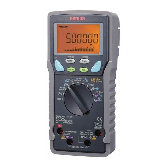
[3] Parts Identification How to detach the light shielding magnet cap Light shielding magnet cap 3-1 Multimeter and Test Leads Light shielding magnet cap Optical communication unit connector LCD display ⇒ Range hold button (dBm-Ω button) Attached Select button (Back light button) Turn the light shielding magnet cap counterclockwise to detach. -
Page 45: Description Of Functions
3-2 Display [4] DESCRIPTION OF FUNCTIONS ⑨ ⑪ ⑧ ⑱ ⑮ ⑦ ⑤ 4-1 Power Switch/Function Selector Turn the switch to turn on/off the power and select a measuring ⑩ function. All segments of the LCD display will be turned on for 1 ⑫... -
Page 46: Low Battery Indication
4-2-2 How to disable the Auto Power Saving 「 」 ・ : [Ω] ⇒ [ ] ⇒ [ nS ] ⇒ [Ω] ⇒ … Press the SELECT button while turning the meter power on. 「 」 ・ : [ C ] ⇔ [ F ] ( C: ℃ , F: Release the SELECT button after dSAPO is indicated. -
Page 47: Range Hold
4-6 Range Hold 4-9 PC (Personal Computer) Interface Press the RANGE HOLD button to select manual-ranging, and the The instrument equips with an optical isolated interface port at the meter will remain in the range it was in. ( turns off.) In meter back for data communication. -
Page 48: Test Leads Improper Connection Warning
4-10 Test Leads Improper Connection Warning 4-13 Relative Measurement The meter beeps as well as displays “InErr” to warn the user Press the REL button to activate the relative measurement against possible damage to the meter due to test leads improper mode and indicator turns on. -
Page 49: Messages On The Display
Root Mean Average Crest Form [5] Measuring procedures 0 to PEAK Input Waveform Square Value Value Factor Factor Vavg Vp/Vrms Vrms/Vavg Vrms π 5-1 Pre-operational Check − − √ − Sinusoidal √ √ π π 2π wave =0.707Vp =1.111 =0.637Vp =1.414 WARNING 1. -
Page 50: Ac Voltage ( )/Frequency (Hz) Measurement
「 」 START (Max. rated input voltage: 1,000 V dc/ac) • AC Voltage ( )/Frequency (Hz) simultaneous measurement for Variable Frequency Drive (VFD) through the Low-pass filter (LPF) Damaged Meter/Test leads damaged? WARNING 1. Do not apply any input signal exceeding the max. rated input voltage. - Page 51 Note: / Hz Hz / • Press the SELECT button to alternately change the display style. • By default, voltage is always set at manual-range 500 V to best cope with most Variable Frequency Drives (VFD) measurements. Press the RANGE button to select other ranges only when needed.
-
Page 52: Ac Voltage ( ), Decibel (Dbm)/Frequency (Hz)
「 」 Hz / / Hz (Max. rated input voltage: 1,000 V dc/ac) • AC Voltage ( ), Decibel (dBm) / Frequency (Hz) simultaneous measurement WARNING 1. Do not apply any input signal exceeding the max. rated input voltage. 2. Do not switch the function selector while measuring. 3. -
Page 53: Measurement
「 」 dBm/Hz (Max. rated input voltage: 1,000 V dc/ac) ・ DC Voltage( ) measurement ・ DC Voltage( )/AC Voltage( ) simultaneous measurement ・ DC+AC voltage( )/AC Voltage( ) simultaneous measurement WARNING 1. Do not apply any input signal exceeding the max. rated input voltage. RANGE 2. - Page 54 (500000-count) 1Sec. Note: • Press the 500000 ( Δ REL) button for 1 second or more to turn the 500000-count display mode on. It is available to single display DC Voltage function ranges. Measuring speed is reduced to 1.25 times per second. To turn the 500000-count display mode off, press the 500000 ( Δ...
-
Page 55: D%) Measurement
「 」 (Max. rated input voltage: 10 V dc/ac) 3) Measuring procedure ① Connect the red plug of the test lead to the VHz measuring ・ DC voltage (m ) measurement terminal and the black one to the COM terminal. ②... - Page 56 Note: ・ The display style of [m /m ], [m /m ], [ or [ D%] does not show the bar graph. ― 29 ― ― 30 ―...
-
Page 57: Ac Voltage ( M ), Decibel (Dbm)/Frequency (Hz)
「 」 5-6 (Max. rated input voltage: 500 mV dc/ac) Hz / m / Hz ・ AC Voltage (m ), Decibel (dBm) / Frequency (Hz) simultaneous measurement WARNING 1. Do not apply any input signal exceeding the max. rated input voltage. - Page 58 「 」 5-7 (Do not apply any voltage or current.) dBm/Hz ・ Resistance (Ω) measurement ・ Conductance (nS) measurement ・ Continuity check ( WARNING Do not apply any voltage or current to the measuring terminals. CAUTION In the case of high resistance measurement, readings may be unstable due to external inductive influence.
- Page 59 3) Measuring procedure ① Connect the red plug of the test lead to measuring terminal and the black one to the COM terminal. ② Set the function selector to ③ Press the SELECT button to select a function you want to perform.
-
Page 60: Temperature Measurement
「 」 5-8 (Max. rated input voltage: 50 mV dc) Temp Temp ・ Temperature measurement ( ℃ ) or ( ( For K-type thermocouple) WARNING 1. Pay attention in order to avoid risk of burn depending on the object temperature or measuring environment. 2. -
Page 61: Capacitance ( ) Measurement, Diode ( ) Test
「 」 5-9 (Do not apply any voltage or current.) ・ Capacitance ( ) measurement ・ Diode ( ) test WARNING 1. Do not apply any voltage or current to the measuring terminals. 2. Measuring live circuit may damage the meter. 5-9-1 Capacitance ( ) measurement CAUTION... - Page 62 5-9-2 Diode ( ) test What to measure (Diode test): Judging the diode (Good or defective) Measuring procedure ① Connect the red plug of the test lead to measuring terminal and the black one to the COM terminal. ② Set the function selector to , then press the SELECT button to select the diode test.
-
Page 63: Dc Current ( )/Ac Current ( )/Dc+Ac Current ( ), Ac Current ( )/ Frequency (Hz), And % 4 ~ 20 Ma Measurement
「 」 「 」 , 5-10-1 Current (mA/μA)/% 4 ~ 20 mA measurement 5-10 • DC current (m ,μ , ) measurement (m , m , m , μ , μ , μ Max. rated input current 500 mA dc/ac) • AC current (m , μ... - Page 64 m /% 4 ~ 20 mA m / m m / m m / Hz Note: In the % 4 ~ 20 mA measurement, loop-current percentage is indicated, being set at 4 mA=0 % and 20 mA=100 %. ― 45 ― ―...
- Page 65 μ / μ μ / μ μ / Hz μ Note: Measuring Frequency (Hz) Frequency range Range Input sensitivity(Sine wave) 500.00 μA 50 μA 5000.0 μA 500 μA 10.00 Hz ~ 10.00 kHz 50.000 mA 5 mA 500.00 mA 50 mA ―...
- Page 66 5-10-2 Current (A) measurement ( , , Max. rated input current AC 10 A dc/ac ) 1) What to measure • (DC current): DC circuit current • (AC current): AC circuit current • (DC current component / AC current component) •...
- Page 67 5-11 Measurements with Optional Products / Hz WARNING 1. Do not apply any input exceeding max. rated input for the separately available accessories. 2. 2. Do not switch the function selector while measuring. CAUTION 1. To make measurements of consumption current for home appliances using a current probe, use a line separator as shown in the drawing below.
- Page 68 ③ Press the RANGE button to set the 5.0000 V range. ⑤ Multiply the reading by 0.1 for 20 A range, and read the ④ Set the range selector knob on the current probe to the 30 A, display directly for 200 A range. 300 A, or 3000 A range.
-
Page 69: Maintenance
To make temperature measurement, connect the temperature throughly to maintain the instrument. probe to the PC7000 connected to the PC on which sanwa's software PC Link7 is installed and running. 2. Calibrate and inspect the instrument at least once a year to 2) Measuring range ensure safety and maintain its accuracy. -
Page 70: Battery And Fuse Replacement
Rear case 6-3 Battery and Fuse Replacement WARNING Battery door 1. Do not open the rear case with live measuring terminals to avoid Battery electric shock. Also, make sure the meter power is OFF, before starting replacement. Fuse 0.4 A/1000 V φ... -
Page 71: After-Sale Service
[7] AFTER-SALE SERVICE provider, listed in our website, in your country with above information. An instrument sent to Sanwa / agent / distributor 7-1 Warranty and Provision without above information will be returned to the customer. Sanwa offers comprehensive warranty services to its end-users and to its product resellers. -
Page 72: Specifications
[8] SPECIFICATIONS Auto Power Approx. 17 minutes after the last operation Saving 8-1 General Specifications IEC61010-1, IEC61010-2-030, IEC61010-2-033 Operation IEC61010-031 Delta-sigma modulation method 50,000 counts: DCV, DCmV, ACV, ACmV, Safety DCA, DCmA, DC μ A, Compliances Category II for 1000 V ac and dc ACA, ACmA, AC μ... -
Page 73: Measuring Range And Accuracy
8-2 Measuring Range and Accuracy AC Voltage ACV and DC+AC Voltage DC+AC V Accuracy: ±(% rdg + dgt) rdg: reading, dgt: least significant digit AC voltage/ Frequency for dual display Temperature: 23 ℃ ±5 ℃ , Humidity: <75 % R.H. Range Accuracy* True RMS voltage and current accuracies are specified from 10 %... - Page 74 DC Voltage/AC Voltage, DC+AC Voltage/AC Voltage for dual display AC Voltage (with low-pass filter for Variable Frequency Drive) Range Accuracy* Range Accuracy* DC, 45 Hz ~ 65 Hz 10 Hz ~ 40 Hz 500.00 mV 5.0000 V 5.0000 V 50.000 V Main display:±...
- Page 75 DC current Resistance Ω Range Accuracy Input resistance** Range Accuracy 500.00 μA ±(0.15 % rdg + 20 dgt) 500.00 Ω ±(0.2 % rdg + 10 dgt) Approx. 100 Ω 5000.0 μA ±(0.1 % rdg + 20 dgt) 5.0000 kΩ 50.000 mA ±(0.15 % rdg + 20 dgt) 50.000 kΩ...
- Page 76 Frequency (Hz) Capacitance Range Input sensitivity* Frequency range*** Range Accuracy* 10.00 Hz ~ 200.0 kHz 500.00 mV 100 mV 50.00 nF ±(0.8 % rdg + 3 dgt) 500.0 nF 5.0000 V 0.6 V 10.00 Hz ~ 100.0 kHz 5.000 μF ±(1.5 % rdg + 3 dgt)...
- Page 77 本社 = 東京都千代田区外神田2−4−4・電波ビル 郵便番号 = 101-0021・電話 = 東京 (03) 3253−4871㈹ 大阪営業所 = 大阪市浪速区恵美須西2−7−2 郵便番号 = 556-0003・電話 = 大阪 (06) 6631−7361㈹ SANWA ELECTRIC INSTRUMENT CO.,LTD. Dempa Bldg., 4-4 Sotokanda2-Chome Chiyoda-Ku,Tokyo,Japan This manual employs soy ink. 04-1405 5008 6010...
Need help?
Do you have a question about the PC7000 and is the answer not in the manual?
Questions and answers