Table of Contents
Advertisement
Quick Links
WarninG: FOr OutdOOr use Only
WARNING:
If the information in these instructions are not followed exactly,
a fire or explosion may result causing property damage,
personal injury or loss of life.
FOR YOUR SAFETY
Do not store or use gasoline or other flammable vapours and
liquids in the vicinity of this or any other appliance.
Installation and service must be performed by a qualified
installer, service agency or the gas supplier.
WARNING:
Improper installation, adjustment, alteration, service or maintenance can cause injury or property
damage. Read the installation, operating and maintenance instructions thoroughly before installing
or servicing this equipment.
Tested by:
919-001e
FIREGEAR OUTDOORS A DIvISION OF SkYTEch II INc. 9230 cONSERvATION WAY, FORT WAYNE, IN 46809
Outdoor 42
Gas Fireplace
Installer: Please complete the details on the back cover
and leave this manual with the homeowner.
Homeowner: Please keep these instructions for future reference.
TEch SUPPORT 1-855-498-8324
A DIVISION OF SKYTECH PRODUCTS GROUP
Owners &
Installation Manual
MODELS: OD42-N
FOR YOUR SAFETY
What to do if you smell gas:
Do not try to light any appliance
Do not touch any electrical switch:
do not use any phone in your
building.
Immediately call your gas supplier
from a neighbor's phone. Follow
the gas supplier's instructions.
If you cannot reach your gas
supplier, call the fire department.
OD42-P
03/18/14
Advertisement
Table of Contents

Summary of Contents for Outdoors Outdoor 42
- Page 1 Installer: Please complete the details on the back cover and leave this manual with the homeowner. Homeowner: Please keep these instructions for future reference. 919-001e FIREGEAR OUTDOORS A DIvISION OF SkYTEch II INc. 9230 cONSERvATION WAY, FORT WAYNE, IN 46809 03/18/14 TEch SUPPORT 1-855-498-8324...
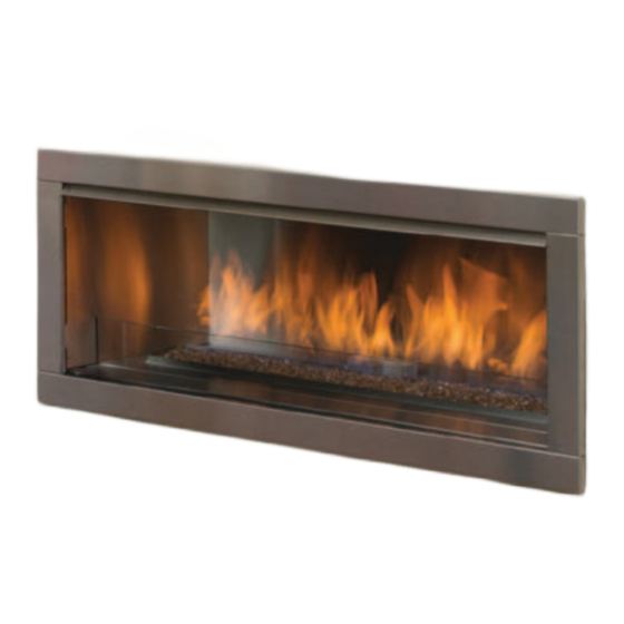
- Page 2 To the New Owner: Congratulations! You are the owner of a state-of-the-art gas fireplace by Firegear Outdoors. The OD42 Outdoor fireplace has been designed to provide you with all the warmth and charm of a fire at the flick of a switch.
-
Page 3: Table Of Contents
table OF cOntents SAFETY LABEL Wiring Diagram ............18 Inner panel installation..........19 Fireglass installation ...........20 Copy of Safety Decal .............4 Twig Set Installation.............21 Heat deflector installation ..........23 DIMENSIONS Faceplate installation ...........24 Glass wind shield installation........25 Weather cover installation / removal ......25 Unit Dimensions with 2"... -
Page 4: Safety Label
OD42 Outdoor Fireplace. We have printed a copy of the contents here for your review. NOTE: Firegear Outdoors units are constantly being improved. Check the label on the unit and if there is a difference, the label on the unit is the correct one. -
Page 5: Dimensions
DIMENSIONS UNIT DIMENSIONS WITh 2" FAcEPLATE OD42 Outdoor Gas Fireplace... -
Page 6: Unit Dimensions With 4" Faceplate
dimensiOns UNIT DIMENSIONS WITh 4" FAcEPLATE OD42 Outdoor Gas Fireplace... -
Page 7: Installation
3) See general construction and assembly this appliance shall be used Only instructions. The appliance should be enclosed. OutdOOrs in a Well-ventilated space and shall nOt be used in 4) Inspect the burner before each use of the a buildinG, GaraGe Or any Other appliance for blockage and any signs of deterioration. -
Page 8: Installation Checklist
installatiOn LOcATING YOUR INSTALLATION GAS FIREPLAcE chEckLIST 1) When selecting a location for your fireplace, ensure that the clearances are met. 1) Locate appliance: 2) This appliance must be installed in an open-air situation with natural ventilation, without stagnant a) Refer to "Locating Your Gas fireplace" section areas, where gas leakage and products of combustion are rapidly dispersed by wind and natural b) Clearances to Combustibles (Refer to convection. -
Page 9: Outdoor Appliance Installation Summary
All Outdoor Fireplace Products have the same need for Air/Oxygen, and an ability to Vent • Even though the appliance is outdoors, this doesn’t mean it is getting • Outdoor appliances must be installed in: open-air situations with natu- adequate air ral ventilation and without stagnant areas •... -
Page 10: Minimum Clearances To Combustibles
installatiOn MINIMUM cLEARANcES TO cOMBUSTIBLES The clearances listed below are Minimum distances unless otherwise stated: A major cause of fires is failure to maintain required clearances (air space) to combustible materials. It is of the greatest importance that this fireplace be installed only in accordance with these instructions. WARNING caution Requirements Fire hazard is an extreme risk... -
Page 11: Framing Dimensions
installatiOn FRAMING DIMENSIONS Framing Description OD42 Dimensions Header Height 32-11/16” (30mm) Side Stud Width 42 - 3/16" (1072mm) Minimum framing depth 20" (508mm) Minimum Height to Combustibles 52 - 1/2" (1334mm) Minimum framing width 60" (1524mm) Corner Wall Depth 40 - 7/16" (1027mm) Corner Facing Wall Width 54 - 3/16"... -
Page 12: Mantel Clearances
installatiOn MANTEL cLEARANcES Due to the extreme heat this fireplace emits, the mantel clearances are critical. Combustible mantel clearances from 12" (305mm) top of front facing are shown in the diagram on the right. Combustible Material Note: Ensure the paint that is used on the mantel and the facing is "heat resistant"... -
Page 13: Finishing
installatiOn FINIShING IMPORTANT FINIShING DETAIL NOTES FOR 2" AND 4" FAcEPLATES: Before placing unit into final position - it is important to know the total thickness / height of finished hearth. The base of the fireplace should be level or higher than the finished hearth height. If material such as brick, stone, etc extends past the faceplate depth (1-1/2"), when finishing around the faceplate, the minimum opening dimensions noted below must be adhered to ensuring for the removal of the faceplate and for the safe operation of this appliance. -
Page 14: High Elevation
Orifice Size #47 DMS Note: If you have an incorrect flame pattern, Maximum Input 43,500 Btu/h contact your Firegear Outdoors dealer ® (12.74 kW) for further instructions. Incorrect flame pattern will have small, probably yellow flames, not coming into proper contact hIGh ELEvATION with the rear burner or flame sensor. -
Page 15: Unit Assembly Prior To Installation
installatiOn UNIT ASSEMBLY PRIOR TO INSTALLATION NAILING STRIPS The 6 Standoffs must be correctly positioned and attached before unit is slid into position. The nailing strips come attached to the unit. There is 1 plate on each side and 1 on the top that can be folded out as required. Secure the top and side nailing strips to the framing. -
Page 16: Drain Installation (Recommended)
DRAIN INSTALLATION (REcOMMENDED) Although this fireplace is designed to operate outdoors safely, rain and other sources of moisture may enter the hearth area, which will cause water to collect inside the base of the unit. to prevent excessive water collection, the installer must provide a way to drain the water from the base of the unit by building or installing a water collector before positioning the fireplace in its location. -
Page 17: Wall Switch Installation
installatiOn BATTERY INSTALLATION/ WALL SWITch INSTALLATION REPLAcEMENT (INcLUDED WITh UNIT) The unit comes with 10' of wire located on the left side of the unit. 1) Remove the front access panel by lifting up and out. Install supplied electrical box in desired location. Route low voltage wire through electrical box. -
Page 18: Wiring Diagram
installatiOn WIRING DIAGRAM This fireplace does not require a 120V A.C. supply for operation. (Do not cut the ground terminal off under any circumstances.) NOTE: 4 AA batteries must be installed in the battery pack to operate the burner switch. Proflame SureFire™... -
Page 19: Inner Panel Installation
HZO42 installatiOn PANEL INSTALLATION INNER PANEL INSTALLATION Before installation, panels must be handled and cleaned as per instructions noted below: Stainless Steel Panels • Stainless panels must be inspected for scratches and dimples prior to installation. All claims to be recorded at this time. Claims for damage after installation will not receive consideration. -
Page 20: Fireglass Installation
installatiOn FIREGLASS INSTALLATION Spread the Fireglass evenly over the burner. Ensure the Fireglass does not overlap too much as this will effect the flame pattern. IMPORTANT NOTE: Only the approved Fireglass is be used with these fireplaces. Use of any other type of Fireglass can alter the unit's performance, any damage caused by the use of any unapproved glass or stones will not be covered under warranty. -
Page 21: Twig Set Installation
installatiOn TWIG SET INSTALLATION Installation of Reflective Panels must be completed before installing the twig set. Read the instructions below carefully and refer to the images. If the twigs are broken do not use the unit until they are replaced. Broken twigs can interfere with pilot operation. - Page 22 installatiOn 4) Install twig D on the burner as shown below. Orient twig D across twig E in the same way and in a similar position as depicted in Diagram 5- twig D will rest up against the back panel. Diagram 5 5) Install twig F on the right side of the burner as shown below.
-
Page 23: Heat Deflector Installation
installatiOn hEAT DEFLEcTOR INSTALLATION 1) Install the heat deflector to the top inside of the firebox with 4 screws as shown below. Heat Deflector Heat Deflector Installed OD42 Outdoor Gas Fireplace... -
Page 24: Faceplate Installation
installatiOn FAcEPLATE INSTALLATION Remove the protective coating from the faceplate before installation - see For installations where thicker finishing material is used - the optional handling instructions in panel install section. trim piece may be installed to fill the gap. Install the trim between the bottom access panel and the faceplate as To install the faceplate - line up the tabs on the faceplate with the 'C' shown below. -
Page 25: Glass Wind Shield Installation
installatiOn GLASS WIND ShIELD INSTALLATION 1) To install the glass wind shield - slot it into the space between the burner tray cover and the bottom access panel - secure with one bracket and one screw on each side. Burner Tray Cover Glass Wind Shield Bracket for Glass Bottom Access panel... - Page 26 installatiOn remOte prOpane / lp Gas enclOsures installatiOn Guidelines If the unit is permanently connected to a gas piping system • Bottom opening must provide a minimum of 1/2 from a remote supply tank, installation must be in accor- square inches (3.23 cm²) for each pound of pro- dance with local codes or, in absence of local codes, with the pane/LP contained in the tank (see example be- National fuel Gas codes ANSI Z223/1.NFPA 54.
-
Page 27: Operating Instructions
OPERATING INSTRUcTIONS installatiOn OPERATING FIRST FIRE INSTRUcTIONS The first fire in your fireplace is part of the paint curing process. To ensure that the paint is properly 1) Read and understand these instructions before cured, it is recommended that you burn your fireplace operating this appliance. -
Page 28: Copy Of Lighting Plate Instructions
OPERATING INSTRUcTIONS cOPY OF LIGhTING PLATE INSTRUcTIONS The lighting plate is located on the underside of the front access panel in the unit. A) This appliance is equipped with an ignition device which automatically lights the pilot. FOR YOUR SAFETY READ BEFORE LIGHTING Do not try to light the pilot by hand. -
Page 29: Maintenance
Failure to do this will result in burn stains on panels which you will be unable to remove. 4) The OD42 is finished in a heat resistant paint and should only be refinished with heat resistant paint. Firegear Outdoors uses StoveBright Paint - Metallic Black #6309. -
Page 30: Valve Assembly Replacement
MAINTENANcE vALvE ASSEMBLY REPLAcEMENT 1) Turn the unit off and allow it to cool down to room temperature. 9) Remove the front access panel by lifting up and out. 2) Turn off the gas supply to the unit. 3) Remove trim. 4) Remove the faceplate by lifting it up and off the unit. - Page 31 MAINTENANcE 12) Slide the burner to the right and lift up and out of the firebox. 13) Remove 6 screws in locations shown below to access DFC. 6th screw located at back 14) Remove 6 screws an lift out valve tray. 16) Replace with new valve tray and reverse steps.
- Page 32 MAINTENANcE DIGITAL FIREPLAcE BURNER cONTROL REMOvAL 5. Disconnect the Black sparker wire with black spade connector from CN3. Remove 6 screws in locations shown below to access DFC. See Diagram 2 below. 6th screw located at back Diagram 2 Sparker Wire 6.
-
Page 33: Main Assembly
parts list MAIN ASSEMBLY Part # Description Part # Description 326-552 2" Faceplate assembly 326-036 Top nailing strip 326-937 4" Faceplate assembly 326-037/F Side nailing strip 326-009 Heat Deflector 940-368/P Glass Windshield 904-777 Orifice # 29 (NG) 904-434 Orifice # 47 (LP) 911-012 (DFC) Digital Fireplace Control 326-574/P... -
Page 34: Burner Assembly
parts list BURNER ASSEMBLY Part # Description Part # Description 326-525 Burner Assembly NG / LP 904-777 Orifice #29 NG 911-024 Valve NG SIT 880 904-434 Orifice #47 LP 911-025 Valve LP SIT 880 911-006 Pilot Assembly NG 326-930 Driftwood Twig Set (Optional) 911-007 Pilot Assembly LP 911-039... -
Page 35: Accessories
parts list AccESSORIES Part # Description 940-368/P Glass Wind shield 326-021 Rear Enamel Panel 326-022 Left Enamel Panel 326-023 Right Enamel Panel 326-552 2" Faceplate Brushed Stainless 326-937 4" Faceplate Brushed Stainless 946-676 Copper Fireglass Part Not Shown OD42 Outdoor Gas Fireplace... - Page 36 nOtes OD42 Outdoor Gas Fireplace...
- Page 37 nOtes OD42 Outdoor Gas Fireplace...
- Page 38 nOtes OD42 Outdoor Gas Fireplace...
-
Page 39: Warranty
Any part or parts of this unit which in our judgement show evidence of such defects will be repaired or replaced at Firegear Outdoors's option, through an accredited distributor or agent provided that the defective part be returned to the distributor or agent Transportation Prepaid, if requested. - Page 40 Firegear Outdoors® fireplaces are designed with reliability and simplicity in mind. In addition, our internal quality Assurance Team carefully inspects each unit thoroughly before it leaves our door. See the inside back cover for details. Installer: Please complete the following information Dealer Name &...
Need help?
Do you have a question about the Outdoor 42 and is the answer not in the manual?
Questions and answers