Table of Contents
Advertisement
Visit our website at
www.MillerWelds.com
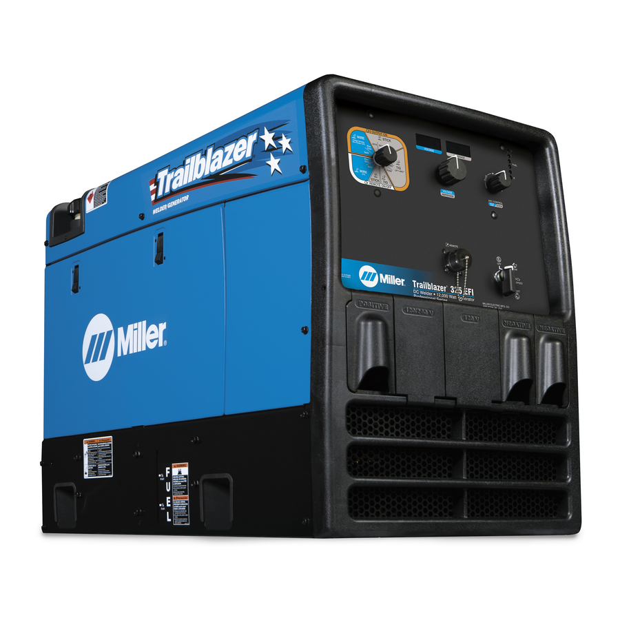
Trailblazer 325
Trailblazer 275
OM-249 795D
2013−02
Processes
MIG (GMAW) Welding
Flux Cored (FCAW)
Stick (SMAW) Welding
TIG (GTAW) Welding
Pulse TIG (GTAW) Welding
Air Plasma Cutting and Gouging
R
with Spectrum
Unit
Air Carbon Arc (CAC-A) Cutting
and Gouging
Description
Engine Driven Welding Generator
R
R
File: Engine Drive
Advertisement
Table of Contents
Troubleshooting


Need help?
Do you have a question about the Trailblazer 325 and is the answer not in the manual?
Questions and answers
Where can I get a schematic for the miller 325 welding machine
new to my current job and this industry period, im working on a miller trailblazer 325 diesel. oil change intervals are usually set at 200hrs for some reason reason on this one its only resetting to 100hrs instead of 200. is there a way to change it from 100 to 200? thanks in advance