Miller Spoolmatic 30A Owner's Manual
Feeder gun
Hide thumbs
Also See for Spoolmatic 30A:
- Owner's manual (53 pages) ,
- Technical manual (76 pages) ,
- Owner's manual (36 pages)

Related Manuals for Miller Spoolmatic 30A


Summary of Contents for Miller Spoolmatic 30A
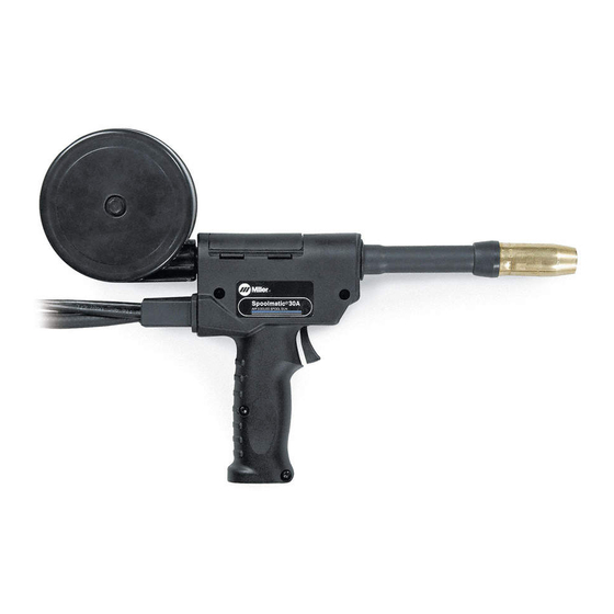
- Page 1 OM-1213 137 531L January 2000 Processes MIG (GMAW) Welding Description Feeder Gun Spoolmatic 30A Visit our website at www.MillerWelds.com...
- Page 2 − every power source from This Owner’s Manual is designed to help you get the most out of your Miller is backed by the most Miller products. Please take time to read the Safety precautions. They will hassle-free warranty in the business.
-
Page 3: Table Of Contents
TABLE OF CONTENTS SECTION 1 − SAFETY PRECAUTIONS - READ BEFORE USING ......1-1. - Page 4 Declaration of Conformity for European Community (CE) Products NOTE This information is provided for units with CE certification (see rating label on unit). Miller Electric Mfg. Co. Manufacturer’s Name: 1635 W. Spencer Street Manufacturer’s Address: Appleton, WI 54914 USA Spoolmatic® 30A...
-
Page 5: Section 1 − Safety Precautions - Read Before Using
SECTION 1 − SAFETY PRECAUTIONS - READ BEFORE USING som _nd_4/98 1-1. Symbol Usage Means Warning! Watch Out! There are possible hazards with this procedure! The possible hazards are shown in the adjoining symbols. This group of symbols means Warning! Watch Out! possible Y Marks a special safety message. - Page 6 ARC RAYS can burn eyes and skin. BUILDUP OF GAS can injure or kill. D Shut off shielding gas supply when not in use. Arc rays from the welding process produce intense visible and invisible (ultraviolet and infrared) rays D Always ventilate confined spaces or use that can burn eyes and skin.
-
Page 7: Additional Symbols For Installation, Operation, And Maintenance
1-3. Additional Symbols For Installation, Operation, And Maintenance FIRE OR EXPLOSION hazard. MOVING PARTS can cause injury. D Do not install or place unit on, over, or near D Keep away from moving parts such as fans. combustible surfaces. D Keep all doors, panels, covers, and guards D Do not install unit near flammables. -
Page 8: Emf Information
1-5. EMF Information Considerations About Welding And The Effects Of Low Frequency 1. Keep cables close together by twisting or taping them. Electric And Magnetic Fields 2. Arrange cables to one side and away from the operator. Welding current, as it flows through welding cables, will cause electro- magnetic fields. -
Page 9: Section 1 − Consignes De Securite − Lire Avant Utilisation
SECTION 1 − CONSIGNES DE SECURITE − LIRE AVANT UTILISATION som _nd_fre 4/98 1-1. Signification des symboles Signifie Mise en garde ! Soyez vigilant ! Cette procédure présente des risques de danger ! Ceux-ci sont identifiés par des symboles adjacents aux directives. Ce groupe de symboles signifie Mise en garde ! Soyez vigilant ! Il y a des Y Identifie un message de sécurité... - Page 10 LES RAYONS DE L’ARC peuvent pro- LES ACCUMULATIONS DE GAZ ris- voquer des brûlures dans les yeux et quent de provoquer des blessures ou sur la peau. même la mort. Le rayonnement de l’arc du procédé de soudage D Fermer l’alimentation du gaz protecteur en cas de génère des rayons visibles et invisibles intenses non utilisation.
-
Page 11: Dangers Supplémentaires En Relation Avec L'installation, Le Fonctionnement Et La Maintenance
1-3. Dangers supplémentaires en relation avec l’installation, le fonctionnement et la maintenance Risque D’INCENDIE OU DES ORGANES MOBILES peuvent D’EXPLOSION. provoquer des blessures. D Ne pas placer l’appareil sur, au-dessus ou à proxi- D Rester à l’écart des organes mobiles comme le mité... -
Page 12: Principales Normes De Sécurité
1-4. Principales normes de sécurité Safety in Welding and Cutting, norme ANSI Z49.1, de l’American Wel- Safe Handling of Compressed Gases in Cylinders, CGA Pamphlet P-1, ding Society, 550 N.W. Lejeune Rd, Miami FL 33126 de la Compressed Gas Association, 1235 Jefferson Davis Highway, Suite 501, Arlington, VA 22202. -
Page 13: Section 2 − Definitions
Section 4-1. = 30V = 1A IP 23 = 100V = 200A X 100% MILLER ELECTRIC MFG. CO., APPLETON, WI USA S-180 481 S-180 481 2-2. Symbols And Definitions NOTE Some symbols are found only on CE products. Primary Voltage... -
Page 14: Section 3 − Installation
SECTION 3 − INSTALLATION 3-1. Specifications Approximate Weld Wire Diameter Cooling Maximum Overall Wire Feed Circuit IP Rating Weight Range Method Spool Size Dimensions Range Rating .025 Thru 1/16 in 2.9 lb 100 Volts, Length: 15-3/8 in (0.6 Thru 1.6 mm) (1.3 kg) Gun 200 Amperes, (390 mm) -
Page 15: Installing Wire Spool And Threading Welding Wire
3-4. Installing Wire Spool And Threading Welding Wire Top Cover Canister Canister Cover Thumbscrew (Canister Cover) Loosen thumbscrew and remove cover. Wire Spool Loosen wire from spool, cut off bent wire, and pull 6 in (150 mm) of wire off spool. Pressure Roll Assembly Lift arm and open pressure roll assembly. -
Page 16: Connecting To 24 Volt Weld Control
3-6. Connecting To 24 Volt Weld Control Gas Hose Connect fitting to regulator/flowme- ter (see Section 3-8). 24 Volt Weld Control Trigger Control Cord Insert plug into receptacle, and tighten threaded collar. Weld Cable Connect to positive (+) weld output terminal on welding power source according to its Owner’s Manual. -
Page 17: Installing Gas Supply
3-8. Installing Gas Supply Obtain gas cylinder and chain to running gear, wall, or other station- ary support so cylinder cannot fall and break off valve. Cylinder Valve Remove cap, stand to side of valve, and open valve slightly. Gas flow blows dust and dirt from valve. -
Page 18: Adjusting Drive Roll And Spool Brake Pressure
3-9. Adjusting Drive Roll And Spool Brake Pressure Top Cover Canister Cover Thumbscrew Loosen thumbscrew and remove cover. Spool Cut welding wire off at contact tip. Retract wire onto spool and secure. Spool Brake Thumbnut Grasp spool in one hand and turn while adjusting spool brake thumb- nut. -
Page 19: Section 4 − Operation
SECTION 4 − OPERATION 4-1. Controls Trigger Press trigger to energize welding power source contactor (if applica- ble), start shielding gas flow, and begin wire feed. For shielding gas preflow and post- flow, lightly press trigger before and after welding. Wire Speed Control Use control to adjust wire feed speed. -
Page 20: Section 5 − Maintenance & Troubleshooting
SECTION 5 − MAINTENANCE & TROUBLESHOOTING 5-1. Routine Maintenance Y Disconnect power Maintain more often before maintaining. during severe conditions. 3 Months Clean Replace Replace Damaged Or Damage Tighten Unreadable Gas Hose Weld Labels Terminals Repair Or Replace Cracked Cables And Cords 6 Months Blow Out Or... -
Page 21: Gun Drive Assembly Maintenance
5-3. Gun Drive Assembly Maintenance Retract wire onto spool. Setscrew Current Pick-Up Tab This tab helps prevent burnback caused by welding arcs inside the contact tip. This tab may be re- moved to provide an insulated drive roll. (If tab is removed, a smaller di- ameter contact tip is recom- mended. -
Page 22: Replacing Canister Inlet Guide
5-4. Replacing Canister Inlet Guide Top Cover Pressure Roll Assembly Cut off welding wire where it enters pressure roll assembly area. Nozzle Pull wire out nozzle. Thumbscrew Canister Cover Loosen thumbscrew and remove cover. Wire Spool Spool Brake Thumbnut Loosen thumbnut, retract wire onto spool, secure, and remove spool. -
Page 23: Replacing Contact Tip Adapter
5-6. Replacing Contact Tip Adapter Barrel Extension Remove as shown. Contact Tip Compression Nut To remove, see Section 5-2. Liner Contact Tip Adapter O-Ring Head Tube Head Tube Setscrew Loosen setscrews and remove adapter. Install new o-ring and adapter, and tighten setscrews. -
Page 24: Section 6 − Electrical Diagram
SECTION 6 − ELECTRICAL DIAGRAM 138 956-C Figure 6-1. Circuit Diagram For Gun/Feeder OM-1213 Page 20... - Page 25 Notes OM-1213 Page 21...
-
Page 26: Section 7 − Parts List
SECTION 7 − PARTS LIST Hardware is common and not available unless listed. 143 116-K Figure 7-1. Complete Assembly OM-1213 Page 22... - Page 27 Item Dia. Part Mkgs. Description Quantity Figure 7-1. Complete Assembly ....133 479 COVER ............
- Page 28 Item Dia. Part Mkgs. Description Quantity Figure 7-1. Complete Assembly (Continued) ....135 474 PIN, hinge ........... . .
- Page 29 Notes OM-1213 Page 25...
- Page 30 Notes OM-1213 Page 26...
-
Page 31: Warranty
Effective January 1, 2000 (Equipment with a serial number preface of “LA” or newer) This limited warranty supersedes all previous Miller warranties and is exclusive with no other Warranty Questions? guarantees or warranties expressed or implied. Call LIMITED WARRANTY − Subject to the terms and conditions Induction Heating Coils and Blankets below, Miller Electric Mfg. - Page 32 Always provide Model Name and Serial/Style Number. Contact your Distributor for: Welding Supplies and Consumables Options and Accessories To locate a distributor or service agency near you, call 1-800-4-A-Miller or visit our Personal Safety Equipment website at www.MillerWelds.com Service and Repair Miller Electric Mfg. Co.
Need help?
Do you have a question about the Spoolmatic 30A and is the answer not in the manual?
Questions and answers