
Related Manuals for Miller Trailblazer 325


Summary of Contents for Miller Trailblazer 325
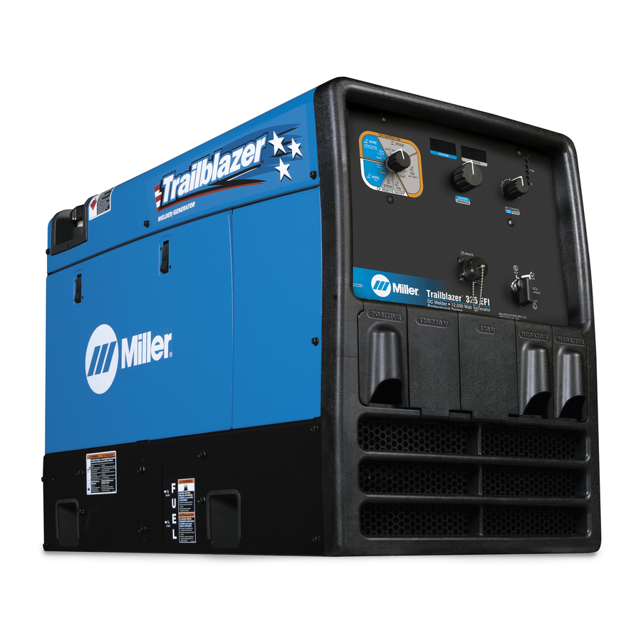
- Page 1 OM-279639R 2023-05 Processes Multiprocess Welding Description Engine Driven Welder/Generator Trailblazer ® OWNER’S MANUAL For product information, Owner’s Manual translations, and more, visit www.MillerWelds.com...
- Page 2 We know you don’t have time to do it any other way. That’s why when Niels Miller first started building arc welders in 1929, he made sure his products offered long-lasting value and superior quality.
-
Page 3: Table Of Contents
TABLE OF CONTENTS SECTION 1 – SAFETY PRECAUTIONS – READ BEFORE USING..............1 Symbol Usage . - Page 4 TABLE OF CONTENTS SECTION 8 – MAINTENANCE AND TROUBLESHOOTING ..............45 Routine Maintenance .
-
Page 5: Section 1 - Safety Precautions - Read Before Using
SECTION 1 – SAFETY PRECAUTIONS – READ BEFORE USING Protect yourself and others from injury—read, follow, and save these important safety precautions and operating instructions. 1-1. Symbol Usage DANGER! – Indicates a hazardous situation which, if not avoided, will result in death or serious injury. The possible hazards are shown in the adjoining symbols or explained in the text. - Page 6 Accidental contact of electrode to metal objects can cause sparks, ex- FLYING METAL OR DIRT can injure plosion, overheating, or fire. Check and be sure the area is safe be- eyes. fore doing any welding. � Welding, chipping, wire brushing, and grinding �...
-
Page 7: Engine Hazards
� Install cylinders in an upright position by securing to a stationary � Turn face away from valve outlet when opening cylinder valve. Do support or cylinder rack to prevent falling or tipping. not stand in front of or behind the regulator when opening the valve. -
Page 8: Compressed Air Hazards
1-4. Compressed Air Hazards � Reinstall doors, panels, covers, or guards when servicing is fin- COMPRESSED AIR EQUIPMENT can ished and before starting unit. injure or kill. � If ANY air is injected into the skin or body seek medical help immediately. - Page 9 � Follow the guidelines in the Applications Manual for the Revised HIGH PRESSURE FLUIDS can injure NIOSH Lifting Equation (Publication No. 94-110) when manually or kill. lifting heavy parts or equipment. � Engine fuel system components can be under high OVERHEATING can damage motors.
-
Page 10: California Proposition 65 Warnings
� If notified by the FCC about interference, stop using the equipment � Be sure all equipment in the welding area is electromagnetically at once. compatible. � Have the installation regularly checked and maintained. � To reduce possible interference, keep weld cables as short as �... -
Page 11: Section 2 - Consignes De Sécurité - Lire Avant Utilisation
SECTION 2 – CONSIGNES DE SÉCURITÉ - LIRE AVANT UTILISATION Pour écarter les risques de blessure pour vous-même et pour autrui — lire, appliquer et ranger en lieu sûr ces consignes relatives aux précautions de sécurité et au mode opératoire. 2-1. - Page 12 � Ne pas toucher aux portes-électrodes qui sont raccordés à deux bien ventilé, et en portant un respirateur à alimentation d’air. Les machines à souder en même temps, car cela entraîne la présence revêtements et tous les métaux renfermant ces éléments peuvent d’une tension de circuit-ouvert double.
-
Page 13: Dangers Existant En Relation Avec Le Moteur
� Ne pas souder là où l’air ambiant pourrait contenir des poussières, � Les porteurs d’implants médicaux doivent consulter leur médecin gaz ou émanations inflammables (vapeur d’essence, par et le fabricant du dispositif avant de s’approcher de la zone où se exemple). -
Page 14: Dangers Liés À L'air Comprimé
� Ne pas placer l’appareil sur, au-dessus ou à proximité de surfaces � Ne pas toucher aux pièces chaudes, utiliser les outils recomman- inflammables. dés et porter des gants de soudage et des vêtements épais pour éviter les brûlures. � Tenir à distance les produits inflammables de l’échappement. LA VAPEUR ET LE LIQUIDE DE Les PIÈCES MOBILES peuvent REFROIDISSEMENT CHAUD peuvent... -
Page 15: Symboles De Dangers Supplémentaires En Relation Avec L'installation, Le Fonctionnement Et La Maintenance
L’AIR COMPRIMÉ risque de Les PIÈCES MOBILES peuvent provoquer des blessures ou même la causer des blessures. mort. � S’abstenir de toucher des parties mobiles telles � Avant d’intervenir sur le circuit d’air comprimé, que des ventilateurs, courroies et rotors. couper l’alimentation électrique, verrouiller etéti- �... - Page 16 � Utiliser uniquement des équipements adéquats pour un fonction- � Régler les commandes de charge de batterie sur la position d’arrêt nement avec une alimentation de 50/60 ou de 60 Hz. avant de brancher la batterie. Veiller à ce que les pinces de charge ne se touchent pas.
-
Page 17: Proposition Californienne 65 Avertissements
� Effectuer l’installation, l’entretien et toute intervention selon les LE SOUDAGE À L’ARC risque de manuels d’utilisateurs, les normes nationales, provinciales et de provoquer des interférences. l’industrie, ainsi que les codes municipaux. � L’énergie électromagnétique risque de provoquer LE RAYONNEMENT HAUTE des interférences pour l’équipement électronique FRÉQUENCE (H.F.) risque de sensible tel que les ordinateurs et l’équipement... - Page 18 les porteurs d’implants médicaux doivent être prises: par exemple, 5. Connecter la pince sur la pièce aussi près que possible de la des restrictions d’accès pour les passants ou une évaluation indivi- soudure. duelle des risques pour les soudeurs. Tous les soudeurs doivent ap- 6.
-
Page 19: Section 3 - Definitions
� Complete Parts List is available at www.MillerWelds.com SECTION 3 – DEFINITIONS Become trained and read the instructions before working on the Become trained and read the instructions before working on the machine or heating. machine or heating. 3-1. Additional Safety Symbol Definitions Safe85 2012 06 Safe85 2012 06 �... - Page 20 Direct Current Welding (FCAW) Percent (DC) Tungsten Inert � Rated No−Load Push Button Complete Parts List is available at www.MillerWelds.com Gas (TIG) Lift Arc Fuel Voltage (OCV) Air Carbon Arc Air Carbon Arc Remote Conventional Cutting (CAC-A) Cutting (CAC-A) Idle (Slow) Remote Load Voltage Rotating Knob...
-
Page 21: Section 4 - Specifications
Information About Default Weld Parameters And Settings NOTICE – Each welding application is unique. Although certain Miller Electric products are designed to determine and default to certain typical welding parameters and settings based upon specific and relatively limited application variables input by the end user, such default settings are for reference purposes only;... -
Page 22: Duty Cycle And Overheating
� Complete Parts List is available at www.MillerWelds.com 4-6. Duty Cycle And Overheating Duty cycle is the percentage of 10 minutes that unit can weld at rated load without overheating. � This unit is rated for welding at 325A continuously. NOTICE –... -
Page 23: Dimensions, Weights, And Operating Angles
� Complete Parts List is available at www.MillerWelds.com 4-7. Dimensions, Weights, And Operating Angles Do not exceed tilt angles or engine could be damaged or unit could tip. Do not move or operate unit where it could tip. Weight: 460 lb (209 kg) w/o fuel 533 lb (242 kg) w/ fuel Lifting Eye Weight Rating: 1280 lb (580 kg) Support Assembly Dimensions... -
Page 24: Static Characteristics
� Complete Parts List is available at www.MillerWelds.com 11-20. Fuel Consumption 4-8. Static Characteristics The static (output) characteristics of the welding power source can be described as flat during the GMAW process and drooping during the SMAW and GTAW processes. Static characteristics are also affected by control settings (including software), electrode, shielding gas, weldment material, and other factors. -
Page 25: Section 5 - Installation
� Complete Parts List is available at www.MillerWelds.com 1-1. Installing Welder/Generator SECTION 5 – INSTALLATION 1-1. Installing Welder/Generator 5-1. Installing Welder/Generator Complete Parts List available at www.MillerWelds.com Do not move or operate unit where Movement it could tip. Do not lift unit from end. Do not weld on base. -
Page 26: 1-1. Grounding Generator To Truck Or Trailer Frame
� Complete Parts List is available at www.MillerWelds.com 5-2. Grounding Generator to Truck or Trailer Frame 1-1. Grounding Generator To Truck Or Trailer Frame GND/PE Bed liners, shipping skids, and 3 Metal Vehicle Frame Always ground generator frame to some running gear insulate the vehicle frame to prevent electric welding generator from the vehicle shock and static electricity hazards. -
Page 27: Engine Prestart Checks
� Complete Parts List is available at www.MillerWelds.com 5-4. Engine Prestart Checks Check all fluids daily. Engine must be cold and on a level surface. Unit is shipped with 10W–30 synthetic blend engine oil. � Follow run-in procedure in engine manual. -
Page 28: Connecting Or Replacing The Battery
� Complete Parts List is available at www.MillerWelds.com 5-5. Connecting Or Replacing The Battery 11-21. Connecting Or Replacing The Battery Connect negative (-) battery cable last. To connect battery, open side access doors. � Do not allow the battery cables to touch opposing terminals. -
Page 29: Weld Output Terminals
� Complete Parts List is available at www.MillerWelds.com 5-6. Weld Output Terminals Stop engine. Turn off power before connecting to weld output terminals. Do not use worn, damaged, under- sized, or repaired cables. 1 Positive (+) Weld Output Terminal 2 TIG/Stick/Gouge Negative (–) Weld Out- put Terminal 3 Wire Negative (–) Weld Output Terminal For MIG welding, connect work cable to Neg-... -
Page 30: Selecting Cable Sizes
� Complete Parts List is available at www.MillerWelds.com 5-8. Selecting Cable Sizes* NOTICE – The Total Cable Length in Weld Circuit (see table below) is the combined length of both weld cables. For example, if the power source is 100 ft (30 m) from the workpiece, the total cable length in the weld circuit is 200 ft (2 cables x 100 ft). Use the 200 ft (60 m) column to determine cable size. - Page 31 Notes...
-
Page 32: Section 6 - Operation
� Complete Parts List is available at www.MillerWelds.com SECTION 6 – OPERATION 6-1. Front Panel Controls (See Section 6-2) 284786-A OM-279639 Page 28... -
Page 33: Description Of Front Panel Controls (See Section 6-1)
� Complete Parts List is available at www.MillerWelds.com 6-2. Description Of Front Panel Controls (See Section 6-1) If no remote control is connected to the Re- welding arc due to resistance of cable and Engine Starting Controls mote receptacle, the front panel Voltage/ connections. -
Page 34: Cold Weather Engine Operation
RPM. If running at more than 3200 RPM, re- the same as Stick/TIG. next highest speed upon arc initiation and turn to idle time is about 9 seconds. transitions down one speed if power is ap- � propriate for load. Miller recommends Hobart filler metals. OM-279639 Page 30... -
Page 35: Process/Contactor Switch
� Complete Parts List is available at www.MillerWelds.com 6-5. Process/Contactor Switch 1 Process/Contactor Switch Weld output terminals are energized when Process/Contactor switch is in an Electrode Hot position and the en- gine is running. Use switch to select weld process and weld output on/off control (see table below). -
Page 36: Service Menu
� Complete Parts List is available at www.MillerWelds.com 6-6. Service Menu 1 Adjust Control/Select Button Press and hold control for 5 seconds, then re- lease to access the Service Menu. Rotate the knob to scroll through the menu items. Press and release the control to access the options and information within each menu item. -
Page 37: Arc Control Settings
� Complete Parts List is available at www.MillerWelds.com 6-7. Arc Control Settings � Arc Control is not active when the Process/Contactor switch is in the following positions: Output On: CAC-A (Air Carbon Arc Gouging) Remote ON/OFF: GTAW (Remote TIG) Complete Parts List is available Process/Contactor Switch Arc Control Complete Parts List is available... -
Page 38: Stick Start Procedure-Scratch Start Technique
Drag electrode across workpiece like striking a match; lift electrode slightly after touching work. If arc goes out electrode was lifted too high. If electrode sticks to workpiece, use a quick twist to free it. � Miller recommends Hobart filler metals. OM-279639 Page 34... -
Page 39: Lift-Arc™ Tig With Auto-Stop™ And Auto-Crater
Remote control is not needed when us- ing Auto-Crater. 1. While welding. 2. Lift torch slightly to start Auto-Crater end (current is reduced). 3. Lower torch. Weld current ramps down. 4. Shielding gas continues until shut off. � Miller recommends Hobart filler metals. OM-279639 Page 35... -
Page 40: 6-10. Remote Voltage/Amperage Control
� Complete Parts List is available at www.MillerWelds.com 6-10. Remote Voltage/Amperage Control 11-23. Remote Voltage/Amperage Control 1 Remote Receptacle RC4 Connect optional remote voltage/amperage (V/A) control to RC4 (see Section 5-9). 2 Process/Contactor Switch With remote control connected, weld output in Stick or TIG is determined by a combina- tion of front panel and remote control volt- age/amperage settings. -
Page 41: 6-11. Updating Software
� Complete Parts List is available at www.MillerWelds.com 6-11. Updating Software Preparing For Software Update Step 1. Verify the current software version installed. Press and hold the Adjust Control/Select button for 5 seconds, then release to access the Service Menu. Step 2. -
Page 42: Summary File
� Complete Parts List is available at www.MillerWelds.com 11-24. Summary File 6-12. Summary File 1 Summary File Each time a USB stick is inserted in the USB receptacle, a summary file is saved to the USB stick as SummaryFile.txt. "USB ACC" will display as the file is written. File is complete when display no longer shows "USB ACC."... -
Page 43: Fuel/Hour Gauge Descriptions
� Complete Parts List is available at www.MillerWelds.com 11-25. Fuel/Hour Gauge Descriptions 6-13. Fuel/Hour Gauge Descriptions OM-279639 Page 39... -
Page 44: Associating Arcreach Devices (Arcreach Models Only)
� Complete Parts List is available at www.MillerWelds.com 6-14. Associating ArcReach Devices (ArcReach Models Only) ® Stop engine. NOTICE – Do not exceed machine duty cycle. Associating ArcReach Device To Engine Driven Welder/Generator Make connections between welder/generator and ArcReach device. See Owner’s Manual for ArcReach device for typical connection diagrams. -
Page 45: Section 7 - Operating Auxiliary Equipment
� Complete Parts List is available at www.MillerWelds.com SECTION 7 – OPERATING AUXILIARY EQUIPMENT 7-1. Generator Power Receptacles Ref. 248009 RC1 supplies 60 Hz single-phase power at CB2 protects RC2 and CB3 protects RC3 Use GFCI protection when operating weld/power speed. Maximum output is 12.0 from overload. -
Page 46: Gfci Receptacle Information, Resetting, And Testing
� Complete Parts List is available at www.MillerWelds.com 7-2. GFCI Receptacle Information, Resetting, And Testing Use GFCI protection when operating If a ground fault is detected, the GFCI Reset Resetting GFCI Receptacles auxiliary equipment. If unit does not button pops out, and the circuit opens to dis- If a GFCI fault occurs, stop engine and dis- have GFCI receptacles, use GFCI- connect power to the faulty equipment. -
Page 47: Optional Excel Power
Ref. 248009 � Complete Parts List is available at www.MillerWelds.com 7-3. Optional Excel Power Excel power option provides generator power at idle speed and while welding. This allows most job site tools to operate properly at engine idle speed. Use GFCI protection when operat- ing auxiliary equipment. -
Page 48: Wiring Instructions For Optional 240 Volt, Single-Phase Plug (Nema 14-50P)
� Complete Parts List is available at www.MillerWelds.com 7-5. Wiring Instructions For Optional 240 Volt, Single-Phase Plug (NEMA 14-50P) The plug can be wired for a 240 V, 2-wire load or a 120/240V, 3-wire load. See circuit diagram. 1 Plug Wired for 120/240 V, 3-Wire Load When wired for 120 V loads, each duplex re- ceptacle shares a load with one half of 240 V 120V... -
Page 49: Section 8 - Maintenance And Troubleshooting
� Complete Parts List is available at www.MillerWelds.com SECTION 8 – MAINTENANCE AND TROUBLESHOOTING 8-1. Routine Maintenance � Also see Voltmeter/Ammeter displays to assist in scheduling maintenance (see Section 8-9). The Voltmeter and Ammeter display total en- gine operating hours at start-up. �... -
Page 50: Maintenance Label
� Complete Parts List is available at www.MillerWelds.com 8-2. Maintenance Label OM-279639 Page 46... -
Page 51: Electronic Fuel Injection (Efi) System And Servicing Information
� Complete Parts List is available at www.MillerWelds.com 8-3. Electronic Fuel Injection (EFI) System And Servicing Information NOTICE – EFI system components can be damaged if these precautions are not followed: � Do not disconnect or reconnect the wiring harness connector to the control unit or any individual components with the Engine Control switch �... -
Page 52: Changing Engine Oil, Oil Filter, And Fuel Filter
� Complete Parts List is available at www.MillerWelds.com 8-5. Changing Engine Oil, Oil Filter, And Fuel Filter tools Stop engine and let cool. 1 Oil Drain Valve 2 Oil Fill 3 Oil Check 4 Full Change engine oil and filter according to en- gine owner’s manual. -
Page 53: Overload Protection
� Complete Parts List is available at www.MillerWelds.com 8-6. Overload Protection 2 Circuit Breaker CB5 (Not Shown) continues to fail, contact Factory Authorized Stop engine. Service Agent. Open left side door. CB5 protects the optional Excel power wind- Close left side door. ings from overload. -
Page 54: Servicing Optional Spark Arrestor
� Complete Parts List is available at www.MillerWelds.com 8-8. Servicing Optional Spark Arrestor Stop engine and let cool. 250916-A 1 Spark Arrestor Screen Clean and inspect screen. Replace spark ar- restor if screen wires are broken or missing. tools/ flathead philips head wrench crescent wrench... -
Page 55: 8-10. Troubleshooting Tables
� Complete Parts List is available at www.MillerWelds.com 8-10. Troubleshooting Tables A. Welding Trouble Remedy No weld output. Check weld control settings. Check weld connections. Disconnect equipment from generator power receptacles during start-up. Increase front panel and/or remote voltage/amperage control settings (see Sections 5-9 and 6-1). Check and secure connections to Remote receptacle RC4 (see Section 5-9). - Page 56 � Complete Parts List is available at www.MillerWelds.com B. Generator Power Trouble Remedy No power output. Reset supplementary protectors CB1, CB2 and/or CB3 (see Section 7-1). Have Factory Authorized Service Agent check brushes, slip rings, and circuit boards PC1 and PC2. No Excel power output.
-
Page 57: Section 9 - Parts List
� Complete Parts List is available at www.MillerWelds.com SECTION 9 – PARTS LIST 9-1. Recommended Spare Parts Recommended Spare Parts Item No. Dia. Mkgs. Part No. Description Quantity 284184 USB Flash Drive F1, F2 215619 Fuse, 10 Amp Ato Type (Kohler ECH730) 215621 Fuse, 30 Amp Ato Type (Kohler ECH730) 012655... -
Page 58: Section 10 - Electrical Diagrams
SECTION 10 – ELECTRICAL DIAGRAMS Figure 10-1. Circuit Diagram For Welder/Generator OM-279639 Page 54... - Page 59 OM-279639 Page 55...
-
Page 60: Section 11 - Generator Power Guidelines
SECTION 11 – GENERATOR POWER GUIDELINES � The views in this section are intended to be representative of all engine-driven welder/generators. Your unit may differ from those shown. 11-1. Selecting Equipment 1 Generator Power Receptacles – Neutral Bonded To Frame 2 3-Prong Plug From Case Grounded Equipment 3 2-Prong Plug From Double Insulated... - Page 61 11-3. Grounding When Supplying Building Systems 1 Equipment Grounding Terminal 2 Grounding Cable GND/PE Use #8 AWG or larger insulated copper wire. 3 Ground Device � Use ground device as stated in electri- cal codes. Ground generator to system earth ground if supplying power to a premises (shop,...
- Page 62 11-5. Approximate Power Requirements For Industrial Motors Industrial Motors Rating Starting Watts Running Watts Split Phase 1/8 HP 1/6 HP 1225 1/4 HP 1600 1/3 HP 2100 1/2 HP 3175 Capacitor Start-Induction Run 1/3 HP 2020 1/2 HP 3075 3/4 HP 4500 1400 1 HP...
- Page 63 11-7. Approximate Power Requirements For Contractor Equipment Contractor Equipment Rating Starting Watts Running Watts Hand Drill 1/4 in. 3/8 in. 1/2 in. Circular Saw 6-1/2 in. 7-1/4 in. 8-1/4 in. 1400 1400 Table Saw 9 in. 4500 1500 10 in. 6300 1800 Band Saw...
- Page 64 11-8. Power Required To Start Motor 1 Motor Start Code 2 Running Amperage 3 Motor HP 4 Motor Voltage AC MOTOR VOLTS AMPS Step 1: Find code and use table to find kVA/ CODE HP. If code is not listed, multiply running am- PHASE perage by six to find starting amperage.
- Page 65 11-10. Typical Connections To Standby Power 1. Utility Electrical 2. Transfer Switch 3. Fused Disconnect 4. Welder/Generator Service Switch (If Required) Output 5. Essential Loads Have only qualified persons perform 1 Utility Electrical Service 4 Welder/Generator Output these connections according to all 2 Transfer Switch (Double-Throw) Generator output voltage and wiring must applicable...
- Page 66 11-11. Selecting Extension Cord (Use Shortest Cord Possible) A. Cord Lengths For 120 Volt Loads Use GFCI protection when operating auxiliary equipment. If unit does not have GFCI receptacles, use GFCI-protected extension cord. Do not use GFCI receptacles to power life support equipment. Maximum Allowable Cord Length In ft (m) for Conductor Size In AWG (mm Current (Amperes)
- Page 67 Effective January 1, 2023 (Equipment with a serial number preface of ND or newer) This limited warranty supersedes all previous Miller warranties and is exclusive with no other guarantees or war- ranties expressed or implied. � CoolBelt, PAPR Blower, and PAPR Face...
- Page 68 Appleton, WI 54914 USA tact your distributor and/or equipment manu- facturer’s Transportation Department. International Headquarters–USA USA Phone: 920-735-4505 USA & Canada FAX: 920-735-4134 International FAX: 920-735-4125 For International Locations Visit www.MillerWelds.com ORIGINAL INSTRUCTIONS – PRINTED IN USA © Miller Electric Mfg. LLC 2023-05...
Need help?
Do you have a question about the Trailblazer 325 and is the answer not in the manual?
Questions and answers