Miller Spoolmate 3035 Owner's Manual
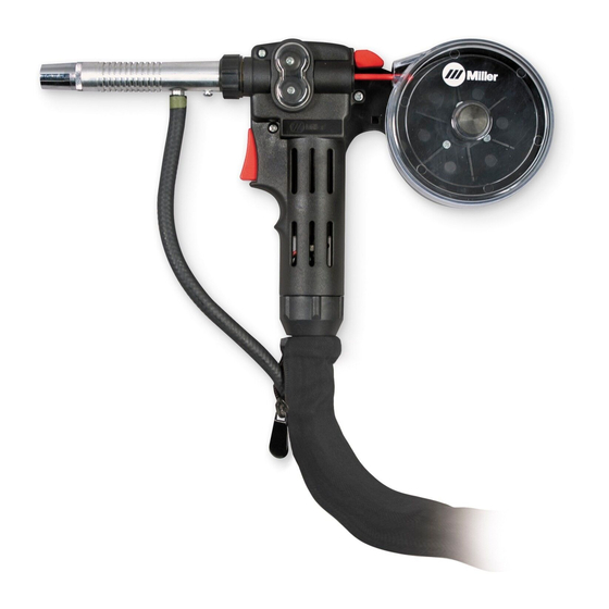
Wire feeder spool gun
Hide thumbs
Also See for Spoolmate 3035:
- Owner's manual (68 pages) ,
- Owner's manual (36 pages) ,
- Owner's manual (28 pages)

Related Manuals for Miller Spoolmate 3035


Summary of Contents for Miller Spoolmate 3035
- Page 1 OM-1216 205 917E 2009−11 Processes MIG (GMAW) Welding Description Wire Feeder Spool Gun ™ Spoolmate 3035 File: Wire Feeder Visit our website at www.MillerWelds.com...
- Page 2 We know you don’t have time to do it any other way. That’s why when Niels Miller first started building arc welders in 1929, he made sure his products offered long-lasting value and superior quality.
-
Page 3: Table Of Contents
..............3-1. Specifications For Spoolmate 3035 . -
Page 5: Section 1 − Safety Precautions - Read Before Using
SECTION 1 − SAFETY PRECAUTIONS - READ BEFORE USING som _2009−08 Protect yourself and others from injury — read and follow these precautions. 1-1. Symbol Usage DANGER! − Indicates a hazardous situation which, if Indicates special instructions. not avoided, will result in death or serious injury. The possible hazards are shown in the adjoining symbols or explained in the text. - Page 6 D Remove stick electrode from holder or cut off welding wire at FUMES AND GASES can be hazardous. contact tip when not in use. D Wear oil-free protective garments such as leather gloves, heavy Welding produces fumes and gases. Breathing shirt, cuffless trousers, high shoes, and a cap.
-
Page 7: Additional Symbols For Installation, Operation, And Maintenance
1-3. Additional Symbols For Installation, Operation, And Maintenance FIRE OR EXPLOSION hazard. MOVING PARTS can injure. D Do not install or place unit on, over, or near D Keep away from moving parts such as fans. combustible surfaces. D Keep all doors, panels, covers, and guards D Do not install unit near flammables. -
Page 8: California Proposition 65 Warnings
1-4. California Proposition 65 Warnings For Gasoline Engines: Welding or cutting equipment produces fumes or gases which contain chemicals known to the State of California to Engine exhaust contains chemicals known to the State of cause birth defects and, in some cases, cancer. (California California to cause cancer, birth defects, or other reproduc- Health &... -
Page 9: Section 2 − Consignes De Sécurité − Lire Avant Utilisation
SECTION 2 − CONSIGNES DE SÉCURITÉ − LIRE AVANT UTILISATION fre_som_2009−08 Se protéger et protéger les autres contre le risque de blessure — lire et respecter ces consignes. 2-1. Symboles utilisés DANGER! − Indique une situation dangereuse qui si on Indique des instructions spécifiques. - Page 10 Il reste une TENSION DC NON NÉGLIGEABLE dans LE SOUDAGE peut provoquer un les sources de soudage onduleur UNE FOIS incendie ou une explosion. l’alimentation coupée. Le soudage effectué sur des conteneurs fermés tels D Arrêter les convertisseurs, débrancher le courant électrique et que des réservoirs, tambours ou des conduites peut décharger les condensateurs d’alimentation selon les instructions provoquer leur éclatement.
-
Page 11: Dangers Supplémentaires En Relation Avec L'installation, Le Fonctionnement Et La Maintenance
ACCUMULATIONS LES BOUTEILLES peuvent exploser risquent de provoquer des blessures si elles sont endommagées. ou même la mort. Des bouteilles de gaz protecteur contiennent du gaz sous haute pression. Si une bouteille est endom- D Fermer l’alimentation du gaz protecteur en cas magée, elle peut exploser. -
Page 12: Proposition Californienne 65 Avertissements
Les PIÈCES MOBILES peuvent RAYONNEMENT HAUTE causer des blessures. FRÉQUENCE (H.F.) risque provoquer des interférences. D Ne pas s’approcher des organes mobiles. D Ne pas s’approcher des points de coincement D Le rayonnement haute fréquence (H.F.) peut tels que des rouleaux de commande. provoquer des interférences avec les équi- pements de radio−navigation et de com- munication, les services de sécurité... -
Page 13: Principales Normes De Sécurité
2-5. Principales normes de sécurité Safety in Welding, Cutting, and Allied Processes, ANSI Standard Z49.1, 25 West 43rd Street, New York, NY 10036 (téléphone : 212-642-4900, de Global Engineering Documents (téléphone : 1-877-413-5184, site site Internet : www.ansi.org). Internet : www.global.ihs.com). Standard for Fire Prevention During Welding, Cutting, and Other Hot Safe Practices for the Preparation of Containers and Piping for Welding Work, NFPA Standard 51B, de National Fire Protection Association,... - Page 14 OM-1216 Page 10...
-
Page 15: Section 3 − Installation
SECTION 3 − INSTALLATION 3-1. Specifications For Spoolmate 3035 Approximate Cooling Maximum Spool Weld Circuit Overall Wire Diameter Range Wire Feed Weight Method Size Rating Dimensions Range .023 Thru .035 in. Length: (0.8 Thru 0.9 mm) 100 Volts, 150 11-1/2 in. (291 mm) -
Page 16: Connecting Spool Gun To Millermatic 212
3-3. Connecting Spool Gun To Millermatic 212 Gun Trigger Plug Insert plug into receptacle, and tighten threaded collar. Weld Cable Shielding Gas Hose Route weld cable through opening in front panel. Route gas hose along side panel or if unit has a hole in the rear panel, gas hose can be routed through wire compartment. -
Page 17: Connecting Spool Gun To Millermatic 210
3-4. Connecting Spool Gun To Millermatic 210 Barbed Fitting If spool gun gas hose is equipped with a pre-installed barbed fitting, cut off fitting from end of hose. Connect spool gun gas hose to barbed fitting. Gun Trigger Plug Insert plug into receptacle labeled “SPOOL GUN”, tighten... -
Page 18: Installing Wire Spool And Threading Welding Wire
3-5. Installing Wire Spool And Threading Welding Wire Thumb Screw Spool Cover Remove thumb screw and spool Tools Needed: cover. Hub Tension Nut Wire Spool Install spool so wire feeds from top. Turn hub tension nut just so a slight drag is felt on the wire spool. -
Page 19: Section 4 − Operation
SECTION 4 − OPERATION 4-1. Controls Spool Gun On/Off switch in Millermatic Hobart IronMan 210 or IronMan 250 must be in On position for spool gun operation (see Field Kit 207 642 instructions). Shielding Gas Cylinder For shielding gas connections, see welding power source Owner’s Manual. -
Page 20: Changing Drive Rolls
5-2. Changing Drive Rolls Y Turn Off power at welding power source first. Drive Roll Cover Remove cover. Changing Push Roll: To remove push roll: Push Roll Screw Washer Push Roll Remove screw and washer, and lift out drive roll. To install drive roll: Slide drive roll onto shaft and se- cure with washer and screw. -
Page 21: Changing Liner
5-3. Changing Liner Y Turn Off power at welding power source first. Nozzle Contact Tip Liner Remove and replace liner. Reinstall parts as shown. Tools Needed: Ref. 801 891-B 5-4. Troubleshooting Trouble Remedy Gun tube assembly loose. Tighten nut at base of gun tube assembly. No weld output;... - Page 22 Notes OM-1214 Page 18...
-
Page 23: Section 6 − Electrical Diagrams
SECTION 6 − ELECTRICAL DIAGRAMS 186 451 Figure 6-1. Circuit Diagram OM-1216 Page 19... -
Page 24: Section 7 − Parts List
SECTION 7 − PARTS LIST Hardware is common and not available unless listed. 801 900-F Figure 7-1. Complete Assembly For Spoolmate 3035 OM-1216 Page 20... - Page 25 Item Dia. Part Quantity Mkgs. Description Figure 7-1. Complete Assembly for Spoolmate 3035 ... 186 416 TRIGGER SWITCH ..........
- Page 26 204 161 Figure 7-2. Spoolmate Optional Hose & Cables Extension Kit Item Part Quantity Description 194 996 Figure 7-2. Spoolmate Hose & Cables Extension Kit ..172 171 FITTING, hose, brass ............
- Page 27 Effective January 1, 2009 (Equipment with a serial number preface of LK or newer) This limited warranty supersedes all previous Miller warranties and is exclusive with no other Warranty Questions? guarantees or warranties expressed or implied. LIMITED WARRANTY − Subject to the terms and conditions...
- Page 28 Contact the Delivering Carrier to: File a claim for loss or damage during shipment. For assistance in filing or settling claims, contact your distributor and/or equipment manufacturer’s Transportation Department. © ORIGINAL INSTRUCTIONS − PRINTED IN USA 2009 Miller Electric Mfg. Co. 2009−01...
Need help?
Do you have a question about the Spoolmate 3035 and is the answer not in the manual?
Questions and answers