Table of Contents
Troubleshooting

Related Manuals for Miller INTEGRA 183


Summary of Contents for Miller INTEGRA 183
- Page 1 OM-188 415C October 2000 Effective with serial number: 165748 Processes MIG (GMAW) Welding Flux Cored (FCAW) Welding Description Arc Welding Power Source and Wire Feeder INTEGRA 183/243/323 Visit our website at www.MillerWelds.com...
- Page 2 1929, he made sure his products offered long-lasting value and superior quality. Like you, his customers couldn’t afford anything less. Miller products had to be more than the best they could be. They had to be the best you could buy.
-
Page 3: Table Of Contents
TABLE OF CONTENTS SECTION 1 – SAFETY PRECAUTIONS - READ BEFORE USING ..1-1. Symbol Usage ..........1-2. - Page 4 Declaration of Conformity Manufactruer’s Name: MILLER Europe S.P.A. Manufacturer’s Address: Via Privata Iseo, 6/E 20098 San Giuliano Milanese, Italy Declares that this product: INTEGRA 183/243/323 Conforms to the following Directives and Standards: Directives Electromagnetic Compatibility Directives: 89/336/EEC Low Voltage: 73/23/EEC...
-
Page 5: Section 1 - Safety Precautions - Read Before Using
SECTION 1 – SAFETY PRECAUTIONS - READ BEFORE USING som _nd_4/98 1-1. Symbol Usage Means Warning! Watch Out! There are possible hazards with this procedure! The possible hazards are shown in the adjoining symbols. This group of symbols means Warning! Watch Out! possible Y Marks a special safety message. - Page 6 ARC RAYS can burn eyes and skin. BUILDUP OF GAS can injure or kill. D Shut off shielding gas supply when not in use. Arc rays from the welding process produce intense D Always ventilate confined spaces or use visible and invisible (ultraviolet and infrared) rays that can burn eyes and skin.
-
Page 7: Additional Symbols For Installation, Operation, And Maintenance
1-3. Additional Symbols For Installation, Operation, And Maintenance FIRE OR EXPLOSION hazard. MOVING PARTS can cause injury. D Do not install or place unit on, over, or near D Keep away from moving parts such as fans. combustible surfaces. D Keep all doors, panels, covers, and guards D Do not install unit near flammables. -
Page 8: Emf Information
1-5. EMF Information Considerations About Welding And The Effects Of Low Frequency 1. Keep cables close together by twisting or taping them. Electric And Magnetic Fields 2. Arrange cables to one side and away from the operator. Welding current, as it flows through welding cables, will cause electro- magnetic fields. -
Page 9: Section 2 - Installation
SECTION 2 – INSTALLATION 2-1. Specifications Rated Input Amperage at Max. Open Rated Output Rated Output Circuit 100% Voltage 230 V 400 V Model Dimension (mm) Weight (kg) 80 A 110 A 180 A 16 A 310 x 540 x 957 18 V 19 V 23 V... -
Page 10: Volt-Ampere Curves
2-3. Volt-Ampere Curves The volt-ampere curves show the normal minimum and maximum Model 183 voltage and amperage output capa- bilities of the welding power source. Curves of other settings fall be- tween the curves shown. Model 243 Model 323 dwg. 802000, 802002, 802001 OM-188 415 Page 6... -
Page 11: Installing Gas Supply
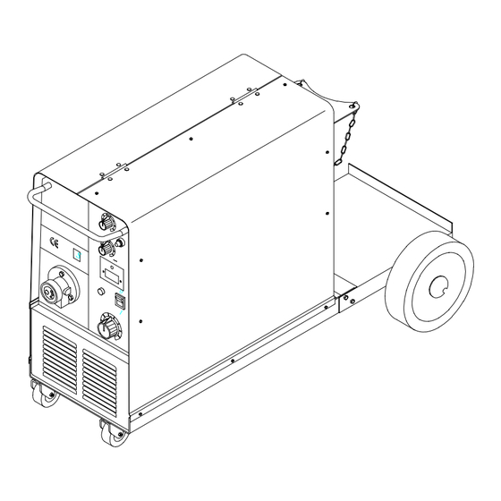
2-4. Installing Gas Supply Chain gas cylinder to running gear, wall, or other stationary support so cylinder cannot fall and break off valve. Regulator/Flow Gauge Install so face is vertical. Gas Hose Connection Flow Adjust Typical flow rate is 20 cfh (cubic feet per hour). -
Page 12: Installing Wire Spool And Adjusting Hub Tension
2-6. Installing Wire Spool and Adjusting Hub Tension When a slight force is needed to turn spool, tension is set. Tools Needed: 15/16 in ST-072573-B 2-7. Positioning Jumper Links Check input voltage available at site. Jumper Links Access Remove side panel. Jumper Link Label Check label –... -
Page 13: Selecting A Location And Connecting Input Power
2-9. Selecting a Location and Connecting Input Power Have only qualified persons make this installation. Rating Label Supply correct input power. 18 in (457 mm) for airflow GND/PE GND/PE Connect First ST-801 721 2-10. Installing Work Clamp Wire Feeder Connection Work Connect Negative Power Source Terminal... -
Page 14: Section 3 - Operation
SECTION 3 – OPERATION 3-1. Controls Handle Wire Speed Control Pilot Light Spot Timer Optional Amperage and Volt- meter Power Switch Thermal Overload Pilot Light 10 Position Voltage Control Torch Connector OM-188 415 Page 10... -
Page 15: Section 4 - Maintenance And Troubleshooting
SECTION 4 – MAINTENANCE AND TROUBLESHOOTING 4-1. Routine Maintenance Y Disconnect power before maintaining. 3 Months Repair or replace Replace unreadable labels. cracked weld cable. Clean and tighten weld terminals. 6 Months Blow out or vacuum inside. During heavy service clean monthly. 4-2. -
Page 16: Troubleshooting
4-4. Troubleshooting Trouble Remedy No weld output; wire does not feed. Be sure line disconnect switch is On (see Section 2-9). Replace building line fuse or reset circuit breaker if open (see Section 2-9). Reset circuit breaker CB1. Secure gun trigger connections. Check and replace Power switch if necessary. -
Page 17: Section 5 - Electrical Diagram
SECTION 5 – ELECTRICAL DIAGRAM INTEGRA 183 cod.956.142.274 BLACK NERO ROSSO INTEGRA 243 2T – 4T BLACK NERO T.Sw. ROSSO OPTIONAL OPTIONAL OM-188 415 Page 13... - Page 18 INTEGRA 323 cod.956.142.109 OM-188 415 Page 14...
-
Page 19: Section 6 - Parts List
SECTION 6 – PARTS LIST Common Parts Assembly Item Ref. Code Qty. Item Ref. Code Qty. 000151187 PV.0.0.18 156012109 UV.0.0.21 116122284 UV.0.0.14 116121100 UV.0.0.15 156087017 156034001 BP.2.0.19 156009067 057014063 UV.0.7 056054064 VS.0.0.13 056054055 QF.5.0.2 116005165 DZ.0.0.25 156002018 QF.0.0.13 150005001 116122285 UV.0.0.16 156011002 116005316 UV.0.0.17 116123001 DU.0.0.6... - Page 20 Main Assembly (183/243) 12 13 Main Assembly (323) OM-188 415 Page 16...
- Page 21 Qty. Qty. Item Ref. Code 183 243 Item Ref. Code 183 243 323 156018033 056067188 UV.0.0.9 156009079 000046432 OL.0.0.14 156032064 GF.1.04 056092039 EZ.4.0.5 156009075 GF.1.0.2 000097922 BP.2.0.20 000010191 FU.1.0.6 156008912 FU.1.6.1 000058628 FU.1.0.7 056072052 QF.0.10 656102001 BH.0.0.8 056067157 MQ.0.0.1 116009041 CV.0.0.2 056020029 MM.3.0.2 000058628 FU.1.0.7 057052019 QF.0.18...
- Page 22 Notes...
- Page 23 Effective January 1, 2000 This limited warranty supersedes all previous Miller warranties and is exclusive with no other guarantees or warranties expressed or implied. LIMITED WARRANTY – Subject to the terms and conditions APT, ZIPCUT & PLAZCUT Model Plasma Cutting below, Miller Electric Mfg.
- Page 24 Phone: 414-735-4505 USA & Canada FAX: 920-735-4134 International FAX: 920-735-4125 European Headquarters – United Kingdom Phone: 44 (0) 1204-593493 FAX: 44 (0) 1204-598066 Miller Europe Italy Phone: 39 (0) 2982901 PRINTED IN USA 2000 Miller Electric Mfg. Co. 1/00...
Need help?
Do you have a question about the INTEGRA 183 and is the answer not in the manual?
Questions and answers