Table of Contents
Advertisement
Advertisement
Table of Contents

Related Manuals for Miller Big Blue 302D


Summary of Contents for Miller Big Blue 302D
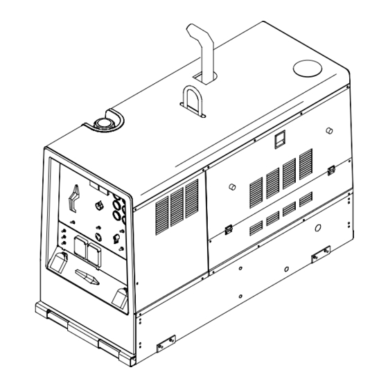
- Page 1 OM-497 197 760A March 2000 Processes Stick (SMAW) Welding TIG (GTAW) Welding MIG (GMAW) Welding Flux Cored (FCAW) Welding Air Carbon Arc (CAC-A) Cutting and Gouging Description Engine Driven Welding Generator Big Blue 302D Visit our website at www.MillerWelds.com...
- Page 2 − every power source from This Owner’s Manual is designed to help you get the most out of your Miller is backed by the most Miller products. Please take time to read the Safety precautions. They will hassle-free warranty in the business.
- Page 3 TABLE OF CONTENTS SECTION 1 − SAFETY PRECAUTIONS - READ BEFORE USING ......1-1. Symbol Usage .
-
Page 4: Table Of Contents
TABLE OF CONTENTS SECTION 8 − MAINTENANCE ............8-1. - Page 5 SECTION 1 − SAFETY PRECAUTIONS - READ BEFORE USING rom _nd_11/98 1-1. Symbol Usage Means Warning! Watch Out! There are possible hazards with this procedure! The possible hazards are shown in the adjoining symbols. This group of symbols means Warning! Watch Out! possible Y Marks a special safety message.
- Page 6 WELDING can cause fire or explosion. HOT PARTS can cause severe burns. D Allow cooling period before maintaining. Welding on closed containers, such as tanks, D Wear protective gloves and clothing when drums, or pipes, can cause them to blow up. Sparks working on a hot engine.
- Page 7 READ INSTRUCTIONS. stopping engine. D Do not let low voltage and frequency caused by D Use only genuine MILLER replacement parts. low engine speed damage electric motors. D Perform engine maintenance and service D Do not connect 50 or 60 Hertz motors to the 100 Hertz receptacle according to this manual and the engine where applicable.
- Page 8 H.F. RADIATION can cause interference. ARC WELDING can cause interference. D High-frequency (H.F.) can interfere with radio D Electromagnetic energy can interfere with navigation, safety services, computers, and sensitive electronic equipment such as communications equipment. computers and computer-driven equipment such as robots. D Have only qualified persons familiar with electronic equipment perform this installation.
- Page 9 SECTION 1 − CONSIGNES DE SÉCURITÉ − LIRE AVANT UTILISATION rom _nd_fre 11/98 1-1. Signification des symboles Signifie Mise en garde ! Soyez vigilant ! Cette procédure présente des risques de danger ! Ceux-ci sont identifiés par des symboles adjacents aux directives. Ce groupe de symboles signifie Mise en garde ! Soyez vigilant ! Il y a des Y Identifie un message de sécurité...
- Page 10 LE SOUDAGE peut provoquer un in- DES PIÈCES CHAUDES peuvent cendie ou une explosion. provoquer des brûlures graves. D Prévoir une période de refroidissement avant d’effec- Le soudage effectué sur des conteneurs fermés tels que tuer des travaux d’entretien. des réservoirs, tambours ou des conduites peut provoquer leur éclatement.
- Page 11 DES ORGANES MOBILES peuvent L’ACIDE DE LA BATTERIE peut pro- provoquer des blessures. voquer des brûlures dans les YEUX et sur la PEAU. D Ne pas approcher les mains des ventilateurs, cour- roies et autres pièces en mouvement. D Ne pas renverser la batterie. D Maintenir fermés et fixement en place les portes, D Remplacer une batterie endommagée.
- Page 12 LE RAYONNEMENT HAUTE FRÉ- LE SOUDAGE À L’ARC risque de QUENCE (H.F.) risque de provoquer provoquer des interférences. des interférences. D L’énergie électromagnétique risque de provoquer des interférences pour l’équipement électronique D Le rayonnement haute fréquence (H.F.) peut sensible tel que les ordinateurs et l’équipement com- provoquer des interférences avec les équipements mandé...
- Page 13 SECTION 2 − DEFINITIONS 2-1. Symbols And Definitions Fast (Run, Weld/ Stop Engine Slow (Idle) Start Engine Power) Engine Oil Starting Aid Battery (Engine) Engine Oil Pressure Check Injectors/ Check Valve Protective Earth Fuel Pump Clearance (Ground) Certified/Trained Positive Negative Welding Arc Mechanic Amperes...
- Page 14 3-2. Dimensions, Weights, And Operating Angles Dimensions 60 in (1524 mm) Height (to top of muffler) 28-1/2 in (724 mm) Y Do not exceed tilt angles or engine could (mtg. brackets turned in) be damaged or unit could tip. Width 30-3/4 in (781 mm) Y Do not move or operate unit where it could (mtg.
- Page 15 3-4. Volt-Ampere Curves For CC/CV Models A. Stick Mode The volt-ampere curves show the minimum and maximum voltage and amperage output capabilities of Ranges the welding generator. Curves of all other settings fall between the 280 − Max curves shown. 160 −...
- Page 16 3-5. Fuel Consumption The curve shows typical fuel use under weld or power loads. 2.00 1.75 1.50 1.25 1.00 0.75 0.50 0.25 IDLE 0.00 DC WELD AMPERES AT 100% DUTY CYCLE 199 032 3-6. Duty Cycle And Overheating Duty Cycle is percentage of 10 min- 100% Duty Cycle At 300 Amperes utes that unit can weld at rated load without overheating.
- Page 17 3-7. AC Auxiliary Power Curve The ac power curve shows the aux- iliary power in amperes available at the 120 and 240 volt receptacles. AC AMPERES IN 240V MODE AC AMPERES IN 120V MODE 193 018 3-8. Optional AC Power Plant Curves The ac power curves show the aux- A.
- Page 18 SECTION 4 − INSTALLATION 4-1. Installing Welding Generator (See Sections 4-2 And 4-3) Movement Airflow Clearance Location 18 in (460 mm) 18 in (460 mm) 18 in (460 mm) 18 in 18 in (460 mm) (460 mm) Grounding Y Always ground generator frame to vehicle frame to pre-...
- Page 19 4-3. Mounting Welding Generator Y Do not weld on base. Weld- ing on base can cause fuel tank fire or explosion. Weld only on the four mounting brackets or bolt unit down. Mounting Bracket 1/2 in Bolt And Washer (Not Supplied) 3/8-16 x 1 in Screws (Supplied)
- Page 20 4-5. Activating The Dry Charge Battery (If Applicable) Remove battery from unit. Eye Protection − Safety Glasses Or Face Shield Rubber Gloves Vent Caps Sulfuric Acid Electrolyte (1.265 Specific Gravity) Well Fill each cell with electrolyte to bottom of well (maximum). Y Do not overfill battery cells.
- Page 21 4-6. Connecting The Battery Y Connect Negative (−) Cable Last. − Tools Needed: 1/2 in 802 168-A / Ref. 197 784 / 802 313 / S-0756-C Notes OM-497 Page 17...
- Page 22 4-7. Engine Prestart Checks Full Diesel Full 802 489 Add fresh diesel fuel before starting to pre- Section 5-1). Check all engine fluids daily. vent air from entering the fuel system (see Engine must be cold and on a level surface. engine maintenance label for fuel specifica- Keep battery in good condition.
- Page 23 4-8. Connecting To Weld Output Terminals Y Stop engine. Positive (+) Weld Output Terminal Negative (−) Weld Output Ter- minal For Stick and TIG welding Direct Current Electrode Positive (DCEP), connect electrode holder cable to Positive (+) terminal on left and work cable to Negative (−) ter- minal on right.
- Page 24 4-10. Connecting To Remote Amperage Adjust Receptacle RC13 On CC Models Remote Amperage Adjust Receptacle RC13 Connect optional remote control to RC13 (see Section 5-3). Ref. 154 862-A / 048 720-K / 802 311 OM-497 Page 20...
- Page 25 4-11. Connecting To Remote 14 Receptacle RC14 On CC/CV Models Socket* Socket Information 24 volts ac. Protected by circuit breaker CB6. 24 VOLTS AC 24 VOLTS AC Contact closure to A completes 24 volt ac contactor control circuit. Output to remote control:+10 volts dc in MIG or Stick mode;...
- Page 26 SECTION 5 − OPERATING WELDING GENERATOR − CC MODELS 5-1. Front Panel Controls For CC Models (See Section 5-2) 10 11 197 784 / 802 311-A OM-497 Page 22...
- Page 27 5-2. Description Of Front Panel Controls For CC Models (See Section 5-1) Engine Starting Controls Engine Temperature Light 13 Ampere Range Switch Light goes on and engine stops if engine oil Magnetic Shutdown Switch temperature is above 266 ° F (130° C). Y Do not switch under load.
- Page 28 5-3. Remote Amperage Control On CC Models (Optional) Remote Amperage Adjust Receptacle RC13 Connect optional remote control to RC13 (see Section 4-10). In Example: Example: Combination Remote Amperage Control (Stick) Range = 120 to 250 A DC Percentage Of Range = 50% Max = About 185 A DC (50% of 120 to 250) Max (185 A DC) Min (74 A DC)
- Page 29 SECTION 6 − OPERATING WELDING GENERATOR − CC/CV MODELS 6-1. Front Panel Controls For CC/CV Models (See Section 6-2) 10 11 197 785 / 802 311 OM-497 Page 25...
- Page 30 6-2. Description Of Front Panel Controls For CC/CV Models (See Section 6-1) Engine Starting Controls Engine Indicator Lights 14 Ampere Range Switch Battery Charging Light Y Do not switch under load. Magnetic Shutdown Switch Light goes on if engine alternator is not charg- ing battery.
- Page 31 6-3. Process/Contactor Switch On CC/CV Models Process/Contactor Switch Y Weld output terminals are en- ergized when Process/Con- tactor switch is in an Electrode Hot position and the engine is running. Use switch to select weld process and weld output on/off control (see table below and Section 6-4).
- Page 32 6-4. Remote Voltage/Amperage Control On CC/CV Models (Optional) Remote 14 Receptacle RC14 Connect optional remote control to RC14 (see Section 4-11). In Example: Example: Combination Remote Amperage Control (Stick) Process = Stick (Using Remote On/Off) Range = 90 to 240 A DC Min = 90 A DC Max = 240 A DC Max (240 A DC)
- Page 33 SECTION 7 − OPERATING AUXILIARY EQUIPMENT 7-1. 120 Volt And 240 Volt Duplex Receptacles 120 V 20 A AC GFCI Receptacle GFCI1 240 V 30 A AC Twistlock Receptacle RC1 Receptacles supply 60 Hz single- phase power at weld/power speed. If a ground fault is detected, GFCI Reset button...
- Page 34 7-2. Connecting To Optional Auxiliary Power Plant (CC/CV Models Only) Place Process/Contactor switch in Electrode Hot - Stick position when using auxiliary power plant (see Section 6-3). Single-Phase Power Connection Place Engine Control switch in Run position when using auxil- iary power plant.
-
Page 35: Section 8 − Maintenance
SECTION 8 − MAINTENANCE 8-1. Maintenance Label Have only trained technician maintain injection pump and injectors. AIR, WATER, or GASOLINE will harm the injection system. If engine has run out of fuel or fuel filter is changed, bleeding of air may be required. -
Page 36: Routine Maintenance
8-2. Routine Maintenance Note Follow the storage procedure in the engine owner’s manual if the unit will not be used for an extended period. Y Stop engine before maintaining. See also Engine Manual and Maintenance Label. Recycle engine Service engine more often if used in severe condi- fluids. -
Page 37: Servicing Air Cleaner
1000 h Change Oil Filter. See Section 8-6. Change Oil. See Service more often Section 8-6. in dirty conditions. Service Welding Generator Brushes Change Fuel And Slip Rings. Filters. See Service More Often Section 8-6. In Dirty Conditions.* Drain Sludge FUEL From Fuel Check... -
Page 38: Inspecting And Cleaning Optional Spark Arrestor Muffler
8-4. Inspecting And Cleaning Optional Spark Arrestor Muffler Y Stop engine and let cool. Spark Arrestor Muffler Cleanout Plug Remove plug and remove any dirt covering cleanout hole. Exhaust Pipe Start engine and run at idle speed to blow out cleanout hole. If nothing blows out of hole, briefly cover end of exhaust pipe with fireproof material. -
Page 39: Adjusting Engine Speed
8-5. Adjusting Engine Speed Y Stop engine and let cool. Engine speed is factory set and should not require adjustment. Af- ter tuning engine, check engine no load speed with a tachometer or fre- quency meter (see table for no load speeds). -
Page 40: Servicing Fuel And Lubrication Systems
8-6. Servicing Fuel And Lubrication Systems Tools Needed: 7/16, 11/16 in Ref. 800 159-E / Ref. 802 170 / 802 489 Y Stop engine and let cool. Fuel Tank Sludge Drain Valve Apply thin coat of fuel to gasket on new filter. Fill filter with fuel. -
Page 41: Overload Protection
8-7. Overload Protection Y Stop engine. When a circuit breaker or fuse opens, it usually indicates a more serious problem exists. Contact Factory Authorized Service Agent. Fuse F1 Fuse F2 F1 and F2 protect the stator exciter winding from overload. If F1 opens, weld and auxiliary power is low or stops entirely. -
Page 42: Diagnosing Causes Of Engine Fault Shutdowns
8-8. Diagnosing Causes Of Engine Fault Shutdowns Use the front panel engine lights to help determine the cause of an au- tomatic engine shutdown. Correct the cause of the shut- Pre-Start Diagnostic Checks down before operating the welding generator. This unit does not have a bat- tery charging fault shutdown. -
Page 43: Troubleshooting Tables
8-9. Troubleshooting Tables A. Welding − CC Models Trouble Remedy No weld output; auxiliary power output Check position of Ampere Range switch. okay. Check position of optional polarity switch. Place Amperage Adjust switch in Panel position, or place switch in Remote position and connect remote control to Remote Amperage Adjust receptacle RC13 (see Sections 4-10 and 5-1). - Page 44 B. Welding − CC/CV Models Trouble Remedy No weld output; auxiliary power output Place Process/Contactor switch in a Electrode Hot position, or place switch in a Remote position and okay. connect remote contactor to optional Remote 14 receptacle RC14 (see Sections 4-11 and 6-1). Check position of Ampere Range switch.
- Page 45 C. Standard Auxiliary Power Trouble Remedy No auxiliary power output; weld output Reset receptacle circuit breakers. okay. No auxiliary power or weld output. Disconnect equipment from auxiliary power receptacles during start-up. Check fuses F1 and F2, and replace if open (see Section 8-7). Have Factory Authorized Service Agent check integrated rectifier SR1, capacitor C9, and the rotor.
- Page 46 Trouble Remedy Engine starts, but stops when Magnetic When starting engine, continue holding Magnetic Shutdown switch until after engine indicator lights go Shutdown switch is released. out. Check oil level. Automatic shutdown system stops engine if oil pressure is too low or engine temperature is too high (see Sections 4-7 and 8-8).
- Page 47 Notes OM-497 Page 43...
-
Page 48: Section 9 − Electrical Diagrams
SECTION 9 − ELECTRICAL DIAGRAMS Figure 9-1. Circuit Diagram For CC Welding Generator OM-497 Page 44... - Page 49 197 279 OM-497 Page 45...
- Page 50 Figure 9-2. Circuit Diagram For CC/CV Welding Generator OM-497 Page 46...
- Page 51 197 277 OM-497 Page 47...
-
Page 52: Section 10 − Run-In Procedure
SECTION 10 − RUN-IN PROCEDURE run_in1 6/96 10-1. Wetstacking Welding Generator Run diesel engines near rated out- put during run-in period to properly seat piston rings and prevent wets- tacking. See nameplate or rating label to find rated output. Do not idle engine longer than necessary. -
Page 53: Run-In Procedure Using Load Bank
10-2. Run-In Procedure Using Load Bank Y Stop engine. Y Do not touch hot exhaust pipe, engine parts, or load bank/grid. Y Keep exhaust and pipe away from flammables. Load Bank Turn all load bank switches Off. If needed, connect load bank to 115 volts ac wall receptacle or genera- tor auxiliary power receptacle. -
Page 54: Run-In Procedure Using Resistance Grid
10-3. Run-In Procedure Using Resistance Grid Y Stop engine. Y Do not touch hot exhaust pipe, engine parts, or load bank/grid. Y Keep exhaust and pipe away from flammables. Resistance Grid Use grid sized for generator rated output. Turn Off grid. Welding Generator Place A/V range switch in maxi- mum position, A/V control in mini-... -
Page 55: Section 11 − Auxiliary Power Guidelines
SECTION 11 − AUXILIARY POWER GUIDELINES 11-1. Selecting Equipment Auxiliary Power Receptacles − Neutral Bonded To Frame 3-Prong Plug From Case Grounded Equipment 2-Prong Plug From Double Insulated Equipment Be sure equipment has this symbol and/or wording. aux_pwr 2/99 − Ref. ST-159 730 / ST-800 577 11-2. - Page 56 11-3. Grounding When Supplying Building Systems Equipment Grounding Terminal Grounding Cable GND/PE Use #10 AWG or larger insulated copper wire. Ground Device Y Ground generator to system earth ground if supplying power to a premises (home, shop, farm) wiring system. Use ground device as stated in electrical codes.
- Page 57 11-5. Approximate Power Requirements For Industrial Motors Industrial Motors Rating Starting Watts Running Watts Split Phase 1/8 HP 1/6 HP 1225 1/4 HP 1600 1/3 HP 2100 1/2 HP 3175 Capacitor Start-Induction Run 1/3 HP 2020 1/2 HP 3075 3/4 HP 4500 1400 1 HP...
- Page 58 11-7. Approximate Power Requirements For Contractor Equipment Contractor Rating Starting Watts Running Watts Hand Drill 1/4 in 3/8 in 1/2 in Circular Saw 6-1/2 in 7-1/4 in 8-1/4 in 1400 1400 Table Saw 9 in 4500 1500 10 in 6300 1800 Band Saw 14 in...
- Page 59 11-8. Power Required To Start Motor Motor Start Code AC MOTOR Running Amperage VOLTS AMPS Motor HP CODE Motor Voltage PHASE To find starting amperage: Step 1: Find code and use table to find kVA/HP. If code is not listed, multiply running amperage by six to find starting amperage.
- Page 60 11-10. Typical Connections To Supply Standby Power Power Company Service Meter Main and Branch Overcurrent Protection Double-Pole, Double-Throw Transfer Switch Obtain and install correct switch. Switch rating must be same as or Customer-supplied equipment is required if greater than the branch overcurrent generator is to supply standby power during protection.
- Page 61 11-11. Selecting Extension Cord (Use Shortest Cord Possible) Cord Lengths for 120 Volt Loads Y If unit does not have GFCI receptacles, use GFCI-protected extension cord. Maximum Allowable Cord Length in ft (m) for Conductor Size (AWG)* Current Load (Watts) (Amperes) 350 (106) 225 (68)
-
Page 62: Section 12 − Parts List
SECTION 12 − PARTS LIST Hardware is common and not available unless listed. 8 (CV) 116 (CV) 115 (CV) 109 (Fig. 12−7) 107 (Fig. 12−2 or 12−3) 104 (CV) 106 (CV) 100 (CC Only) 105 (CV) 102 CC Only) 103 CC Only) 114 (Fig. - Page 63 29 30 36 (Fig. 12−6) 802 559-A OM-497 Page 59...
- Page 64 Item Dia. Part Mkgs. Description Quantity Figure 12-1. Main Assembly ....189 824 PANEL, gen LH ..........
- Page 65 Item Dia. Part Mkgs. Description Quantity Figure 12-1. Main Assembly (Continued) ....*192 744 FILTER, fuel spin-on ..........
- Page 66 Item Dia. Part Mkgs. Description Quantity Figure 12-1. Main Assembly (Continued) ....189 913 ..FITTING, stl barbed elbow zinc pld ....... .
- Page 67 802 551 Figure 12-2. Control Box Assembly − CC Models Item Dia. Part Mkgs. Description Quantity Figure 12-2. Control Box Assembly − CC Models (Figure 12-1 Item 107) ..F1, F2 *085 874 FUSE, mintr cer slo-blo 10A 250V .
- Page 68 802 360 Figure 12-3. Control Box Assembly − CC/CV Models Item Dia. Part Mkgs. Description Quantity Figure 12-3. Control Box Assembly − CC/CV Models (Figure 12-1 Item 107) ..F1, F2 *085 874 FUSE, mintr cer slo-blo 10A 250V .
- Page 69 Hardware is common and not available unless listed. 802 266-B Figure 12-4. Panel, Front w/Components − CC Models OM-497 Page 65...
- Page 70 Item Dia. Part Mkgs. Description Quantity Figure 12-4. Panel, Front w/Components − CC Models (Figure 12-1 Item 114) ....197 784 PLATE SCREENED, ident control rating; when ordering this item, .
- Page 71 Item Dia. Part Mkgs. Description Quantity Figure 12-4. Panel, Front w/Components − CC Models (Continued) ....135 873 CLIP, conduit convoluted 1/2 in mtg hole .
- Page 72 Item Dia. Part Mkgs. Description Quantity Figure 12-5. Panel, Front w/Components − CC/CV Models (Figure 12-1 Item 114) ....197 785 PLATE SCREENED, ident control ; when ordering this item, .
- Page 73 Item Dia. Part Mkgs. Description Quantity Figure 12-5. Panel, Front w/Components − CC/CV Models (Continued) ....039 047 TERMINAL, pwr output red ........
- Page 74 802 552 Figure 12-6. Generator Item Dia. Part Mkgs. Description Quantity Figure 12-6. Generator (Figure 12-1 Item 36) ....132 053 SCREW, .375−16x1.50 hex hd−pln gr5 pld .
- Page 75 Item Dia. Part Mkgs. Description Quantity Figure 12-6. Generator (Continued) ....191 579 COVER, starter hole Perkins/Continental ......
- Page 76 Hardware is common and not available unless listed. 802 279 Figure 12-7. Main Rectifier Assembly Item Dia. Part Mkgs. Description Quantity Figure 12-7. Main Rectifier Assembly (Figure 12-1 Item 109) ....188 137 CONNECTION BOARD, rectifier AC .
- Page 77 Effective January 1, 2000 (Equipment with a serial number preface of “LA” or newer) This limited warranty supersedes all previous Miller warranties and is exclusive with no other Warranty Questions? guarantees or warranties expressed or implied. Call LIMITED WARRANTY − Subject to the terms and conditions Induction Heating Coils and Blankets below, Miller Electric Mfg.
-
Page 78: Options And Accessories
Always provide Model Name and Serial/Style Number. Contact your Distributor for: Welding Supplies and Consumables Options and Accessories To locate a distributor or service agency near you, call 1-800-4-A-Miller or visit our Personal Safety Equipment website at www.MillerWelds.com Service and Repair Miller Electric Mfg. Co.
Need help?
Do you have a question about the Big Blue 302D and is the answer not in the manual?
Questions and answers