Miller Syncrowave 250 DX Owner's Manual
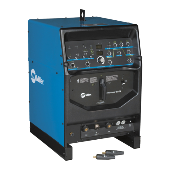
With optional running gear and cooler
Hide thumbs
Also See for Syncrowave 250 DX:
- User manual (68 pages) ,
- Owner's manual (82 pages) ,
- Technical manual (130 pages)
Table of Contents
Troubleshooting

Related Manuals for Miller Syncrowave 250 DX


Summary of Contents for Miller Syncrowave 250 DX
- Page 1 OM-363 213117AS 2015−02 Processes TIG (GTAW) Welding Stick (SMAW) Welding Description Arc Welding Power Source Syncrowave 250 DX / 350 LX With Optional Running Gear And Cooler File: TIG (GTAW) Visit our website at www.MillerWelds.com...
- Page 2 We know you don’t have time to do it any other way. That’s why when Niels Miller first started building arc welders in 1929, he made sure his products offered long-lasting value and superior quality.
-
Page 3: Table Of Contents
TABLE OF CONTENTS SECTION 1 − SAFETY PRECAUTIONS - READ BEFORE USING ........1-1. - Page 4 TABLE OF CONTENTS 6-11. Preflow Time Control ..............6-12.
-
Page 5: Section 1 − Safety Precautions - Read Before Using
SECTION 1 − SAFETY PRECAUTIONS - READ BEFORE USING som 2013−09 Protect yourself and others from injury — read, follow, and save these important safety precautions and operating instructions. 1-1. Symbol Usage DANGER! − Indicates a hazardous situation which, if Indicates special instructions. - Page 6 D Remove stick electrode from holder or cut off welding wire at FUMES AND GASES can be hazardous. contact tip when not in use. D Wear body protection made from durable, flame−resistant material Welding produces fumes and gases. Breathing (leather, heavy cotton, wool). Body protection includes oil-free these fumes and gases can be hazardous to your clothing such as leather gloves, heavy shirt, cuffless trousers, high health.
-
Page 7: Additional Symbols For Installation, Operation, And Maintenance
1-3. Additional Symbols For Installation, Operation, And Maintenance FIRE OR EXPLOSION hazard. MOVING PARTS can injure. D Do not install or place unit on, over, or near D Keep away from moving parts such as fans. combustible surfaces. D Keep all doors, panels, covers, and guards D Do not install unit near flammables. -
Page 8: California Proposition 65 Warnings
1-4. California Proposition 65 Warnings Welding or cutting equipment produces fumes or gases This product contains chemicals, including lead, known to which contain chemicals known to the State of California to the state of California to cause cancer, birth defects, or other cause birth defects and, in some cases, cancer. -
Page 9: Section 2 − Consignes De Sécurité − Lire Avant Utilisation
SECTION 2 − CONSIGNES DE SÉCURITÉ − LIRE AVANT UTILISATION fre_som_2013−09 Pour écarter les risques de blessure pour vous−même et pour autrui — lire, appliquer et ranger en lieu sûr ces consignes relatives aux précautions de sécurité et au mode opératoire. 2-1. - Page 10 D Ne pas raccorder plus d’une électrode ou plus d’un câble de D Avoir recours à des écrans protecteurs ou à des rideaux pour masse à une même borne de sortie de soudage. Débrancher le protéger les autres contre les rayonnements les éblouissements câble pour le procédé...
-
Page 11: Dangers Supplémentaires En Relation Avec L'installation, Le Fonctionnement Et La Maintenance
DES PIECES DE METAL ou DES LES BOUTEILLES peuvent exploser si elles sont endommagées. SALETES peuvent provoquer des blessures dans les yeux. Les bouteilles de gaz comprimé contiennent du gaz sous haute pression. Si une bouteille est D Le soudage, l’écaillement, le passage de la endommagée, elle peut exploser. - Page 12 LES CHARGES ÉLECTROSTATI- RAYONNEMENT HAUTE QUES peuvent endommager les cir- FRÉQUENCE (H.F.) risque cuits imprimés. provoquer des interférences. D Établir la connexion avec la barrette de terre D Le rayonnement haute fréquence (H.F.) peut avant de manipuler des cartes ou des pièces. provoquer des interférences avec les équi- D Utiliser des pochettes et des boîtes antista- pements de radio−navigation et de com-...
-
Page 13: Proposition Californienne 65 Avertissements
2-4. Proposition californienne 65 Avertissements Les équipements de soudage et de coupage produisent des Ce produit contient des produits chimiques, notamment du fumées et des gaz qui contiennent des produits chimiques plomb, dont l’État de Californie reconnaît qu’ils provoquent dont l’État de Californie reconnaît qu’ils provoquent des mal- des cancers, des malformations congénitales ou d’autres formations congénitales et, dans certains cas, des cancers. - Page 14 OM-363 Page 10...
-
Page 15: Section 3 − Definitions
A complete Parts List is available at www.MillerWelds.com SECTION 3 − DEFINITIONS 3-1. Additional Safety Symbols And Definitions Some symbols are found only on CE products. Warning! Watch Out! There are possible hazards as shown by the symbols. Safe1 2012−05 Wear dry insulating gloves. -
Page 16: Miscellaneous Symbols And Definitions
A complete Parts List is available at www.MillerWelds.com Do not remove or paint over (cover) the label. Safe20 2012−05 Do not discard product (where applicable) with general waste. Reuse or recycle Waste Electrical and Electronic Equipment (WEEE) by disposing at a designated collection facility. - Page 17 A complete Parts List is available at www.MillerWelds.com Maximum Rated No Load Effective Supply Initial Amperage Voltage (OCV) 1eff Current Rated Maximum Pulse Percent On Primary Voltage Supply Current Time 1max Conventional Hertz Spot Time Load Voltage Line Connection Electrode Lift-Arct 4 Step Trigger Operation...
-
Page 18: Section 4 − Specifications
A complete Parts List is available at www.MillerWelds.com SECTION 4 − SPECIFICATIONS 4-1. Serial Number And Rating Label Location The serial number and rating information for the power source is located on the front of the machine. Use the rating labels to determine input power requirements and/or rated output. - Page 19 A complete Parts List is available at www.MillerWelds.com B. For 250 DX Models Amperes Input at AC Balanced Rated Rated Load Output, 60 Hz, Single-Phase Peak Rated Starting Amperage Voltage Welding 200V 230V 460V 575V Range (Up) Output (Uo) NEMA Class 17.6 3 −...
-
Page 20: Duty Cycle And Overheating
A complete Parts List is available at www.MillerWelds.com 4-4. Duty Cycle And Overheating Duty Cycle is the percentage of 10 minutes that the unit can weld at rated load without overheating. If unit overheats, output stops, front panel voltmeter/ammeter displays a HLP3 or HLP5 message (see Section 8-1), and cooling fans run. -
Page 21: Volt-Ampere Curves
A complete Parts List is available at www.MillerWelds.com 4-5. Volt-Ampere Curves A. For 250 DX Models The volt-ampere curves show the minimum and maximum voltage and amperage output capabilities of the welding power source. Curves of other settings fall between the curves shown. -
Page 22: Dimensions And Weights
A complete Parts List is available at www.MillerWelds.com 4-6. Dimensions And Weights Dimensions Height 36-1/4 in. (921 mm) Width 23 in. (584 mm) Length 28 in. (711 mm) 25 in. (635 mm) 1-25/64 in. (35 mm) Front 1-5/8 in. (41 mm) 22 in. -
Page 23: Section 5 − Installation
A complete Parts List is available at www.MillerWelds.com SECTION 5 − INSTALLATION 5-1. Selecting A Location Movement Location And Airflow 18 in. (460 mm) 18 in. (460 mm) Ref. 117 264-C / 803 584-C Line Disconnect Device Falling Unit Can Cause Injury. If using lift forks to move unit, be sure forks are long enough to extend Locate unit near correct input power supply. -
Page 24: Weld Output Terminals And Selecting Cable Sizes
****For distances longer than 100 ft (30 m) and up to 200 ft (60 m), use direct current (DC) output only. For distances longer than those shown in this guide, call a factory applications rep. at 920-735-4505 (Miller) or 1-800-332-3281 (Hobart). -
Page 25: Remote 14 Receptacle Information
CB1 (see Section 7-2). RC2 is a designated use re- ceptacle intended only for sup- plying AC power to a Miller-ap- proved cooler. Rear View Front View Ref. 803 588-B / Ref. 803 585-C / Ref. 157 858... -
Page 26: Tig Connections With A Two-Piece Air-Cooled Torch
A complete Parts List is available at www.MillerWelds.com 5-6. TIG Connections With A Two-Piece Air-Cooled Torch Turn Off power before making connections. Gas-In Connection Connect gas hose from gas supply to gas-in connection. Output Selector Switch (See Section 6-2) Switch is shown in DCEN (direct cur- rent electrode negative) position for TIG HF Impulse DCEN welding. -
Page 27: Front Panel Display For Tig Hf Impulse Dcen (Direct Current Electrode Negative)
A complete Parts List is available at www.MillerWelds.com 5-8. Front Panel Display For TIG HF Impulse DCEN (Direct Current Electrode Negative) Front Panel Green on nameplate indicates a For all front panel switch pad TIG function (see Section 6-1 for Correct front panel display for ba- controls: press switch pad to description of controls). -
Page 28: Front Panel Display For Tig Ac
A complete Parts List is available at www.MillerWelds.com 5-9. Front Panel Display For TIG AC Front Panel Green on nameplate indicates a For all front panel switch pad TIG function (see Section 6-1 for controls: press switch pad to description of controls). Correct front panel display for turn on light and enable basic TIG AC welding. -
Page 29: Optional Cooler Connections
° ° ter for operations above 32 F (0 C), or three gallons of Miller coolant part no. 043 810. Gas Out Connection Connect TIG torch gas hose to gas out fitting. Electrode Weld Output... -
Page 30: Stick Connections
A complete Parts List is available at www.MillerWelds.com 5-11. Stick Connections Turn Off power before mak- ing connections. Work Weld Output Terminal Connect work lead to work weld output terminal. Electrode Weld Output Terminal Connect electrode holder to elec- trode weld output terminal. Remote 14 Receptacle If desired, connect remote control to Remote 14 receptacle (see Sec-... -
Page 31: Front Panel Display For Stick Dcep (Direct Current Electrode Positive)
A complete Parts List is available at www.MillerWelds.com 5-12. Front Panel Display For Stick DCEP (Direct Current Electrode Positive) Front Panel Gray on nameplate indicates a For all front panel switch pad Stick function (see Section 6-1 controls: press switch pad to for description of controls). -
Page 32: Front Panel Display For Stick Ac
A complete Parts List is available at www.MillerWelds.com 5-13. Front Panel Display For Stick AC Front Panel Gray on nameplate indicates a For all front panel switch pad Stick function (see Section 6-1 controls: press switch pad to for description of controls). Correct front panel display for turn on light and enable basic Stick AC welding. -
Page 33: Electrical Service Guide
A complete Parts List is available at www.MillerWelds.com 5-14. Electrical Service Guide A. For 250 DX Models Input amperage may be higher than shown in table when Balance Control is in an unbalanced position. All values in both tables were calculated at 60% duty cycle. Actual input voltage cannot exceed ±... - Page 34 A complete Parts List is available at www.MillerWelds.com B. For 350 LX Models Input amperage may be higher than shown in table when Balance Control is in an unbalanced position. All values in both tables were calculated at 60% duty cycle. Actual input voltage cannot exceed ±...
-
Page 35: Placing Jumper Links
A complete Parts List is available at www.MillerWelds.com 5-15. Placing Jumper Links Disconnect and lockout/tag- Label found on 250 DX models with the following stock numbers: input power before 907194, 907194-021 907194-031 and, 907194-032 installing or moving jumper links. Label found on 350 LX models with the following stock numbers: 907198, 907198-011, 907198-021, 907198-031 and 907198-032 Check input voltage available at site. -
Page 36: Connecting Input Power
A complete Parts List is available at www.MillerWelds.com 5-16. Connecting Input Power =GND/PE Earth Ground Tools Needed: 3/8 in. Input9 2013−02 / 803 585-D OM-363 Page 32... - Page 37 A complete Parts List is available at www.MillerWelds.com 5-16 Connecting Input Power (Continued) Welding Power Source Input Power Con- Disconnect Device Input Power Connec- Installation must meet all National and nections tions Local Codes − have only qualified per- sons make this installation. Disconnect Device (switch shown in Strain Relief OFF position)
-
Page 38: Section 6 − Operation
A complete Parts List is available at www.MillerWelds.com SECTION 6 − OPERATION 6-1. Controls (350 LX Nameplates Shown) available. Power Switch Top row of lights in upper left corner are Amperage Adjustment Use switch to turn unit Off and On. On for SMAW. -
Page 39: Output Selector Switch
A complete Parts List is available at www.MillerWelds.com 6-2. Output Selector Switch Output Selector Switch Do not use AC output in damp areas, if movement is confined, or if there is dan- ger of falling. Use AC output ONLY if required for the welding process, and then use a remote control. -
Page 40: Output Control
A complete Parts List is available at www.MillerWelds.com 6-5. Output Control Remote (Standard)Torch Trigger Operation Current (A) Remote (Standard)Torch Trigger Operation Weld Amps Final Slope Initial Amps Final Amps Postflow Preflow Push & Hold Release For Release Foot Or Foot Or Finger Finger Remote Maintained Switch Remote Control... - Page 41 A complete Parts List is available at www.MillerWelds.com Trigger Hold (2T) Current (A) 2T Torch Trigger Operation Weld Amps Final Slope Initial Amps Final Amps Postflow Preflow Push & Release Trigger Push & Release Trigger In Less Than 3/4 Sec. In Less Than 3/4 Sec.
-
Page 42: 4T Momentary, And Mini Logic Trigger Operation (Requires Optional Sequence Controls)
A complete Parts List is available at www.MillerWelds.com 6-6. 4T, 4T Momentary, And Mini Logic Trigger Operation (Requires Optional Sequence Controls) 4T Torch Trigger Operation If unit is equipped with optional Sequence lows the operator to toggle between weld Application: Controls (see Section 6-13), 4T trigger current and final current without breaking Use 4T trigger method when the functions... - Page 43 A complete Parts List is available at www.MillerWelds.com Mini Logic Operation If unit is equipped with optional Sequence from the initial amps level to the main weld welding power source. Controls (see Section 6-13), Mini Logic op- amps level by pressing and releasing the Application: This ability to change amper- eration is available.
-
Page 44: Reconfiguring Trigger Hold For 4T And Mini Logic Control
A complete Parts List is available at www.MillerWelds.com 6-7. Reconfiguring Trigger Hold For 4T And Mini Logic Control Output Control Power Switch To reconfigure Trigger Hold, turn Off power, push and hold Output control button and turn On power switch. Hold button for approximately 7 sec- onds (or until software version num- ber _ _ _ _ _ _-_clears, and meters... -
Page 45: Selecting Tig Starting Characteristics Using Syncro-Startt Technology
A complete Parts List is available at www.MillerWelds.com 6-8. Selecting TIG Starting Characteristics Using Syncro-Startt Technology E− −2− Use this function to select desired TIG start- button and turn On power. Hold button for Press torch trigger or turn Off power to save ing characteristics. -
Page 46: Start Mode
A complete Parts List is available at www.MillerWelds.com 6-9. Start Mode Lift-Arct Start Method 1 − 2 “Touch” Seconds Do NOT Strike Like A Match! Start Mode onds, and slowly lift electrode. An arc will turns off when arc is started, and turns on form when electrode is lifted. -
Page 47: Balance/Dig Control
A complete Parts List is available at www.MillerWelds.com 6-10. Balance/DIG Control Balance/DIG Control Balance Control (AC GTAW): AC Balance controls the cleaning action. Increasing the balance set- ting reduces the oxide cleaning. Adjusting balance: Set the balance level in the AC TIG zone. Make a test weld. -
Page 48: Preflow Time Control
A complete Parts List is available at www.MillerWelds.com 6-11. Preflow Time Control 00.4 Use control to set length of time (0.2, 0.4, Turn power off. Push and hold Process Con- time, press and release Process Control 0.6, 0.8, 1.0, 1.5, 2.0, 2.5, 3.0, 3.5, 4.0, 4.5, trol button and turn On power. -
Page 49: Pulse Controls (Standard On 350 Lx Models, Optional On 250 Dx Models)
A complete Parts List is available at www.MillerWelds.com 6-12. Pulse Controls (Standard On 350 LX Models, Optional On 250 DX Models) On/Off Control Use control to turn pulse function On and Off. Pulser ON LED LED is lit when pulser function is enabled. -
Page 50: Sequence Controls (Optional)
A complete Parts List is available at www.MillerWelds.com 6-13. Sequence Controls (Optional) Initial Time Control See Section 6-14. Initial Amperage Control See Section 6-14. Final Slope Control See Section 6-15. Final Amperage Control See Section 6-15. Spot Time Control See Section 6-16. 6-14. -
Page 51: Final Slope Control And Final Amperage Control
A complete Parts List is available at www.MillerWelds.com 6-15. Final Slope Control And Final Amperage Control Final Slope Control Indicator light is on when Final Slope control function is active. Final Slope control function is inactive when Spot Time function is active. Use control to reduce amperage over a set period of time (0−15 seconds) at the end of the weld cycle when NOT... -
Page 52: Timer/Cycle Counter
A complete Parts List is available at www.MillerWelds.com 6-17. Timer/Cycle Counter 1 2 3 4 5 6 1 2 3 4 5 6 Amperage Control software number and revision for the first seconds, and are read as 1, 234 hours seven seconds. -
Page 53: Resetting Unit To Factory Default Settings (All Models)
A complete Parts List is available at www.MillerWelds.com 6-18. Resetting Unit To Factory Default Settings (All Models) Process Control Amperage Control Output Control Start Control Power Switch To reset all welding power source functions to original factory settings, turn power off. Push and hold the Process, Amperage, Output, and Start controls and turn On power. -
Page 54: Section 7 − Maintenance
A complete Parts List is available at www.MillerWelds.com SECTION 7 − MAINTENANCE 7-1. Routine Welding Power Source Maintenance Disconnect power before maintaining. Maintain more often during severe conditions. Δ = Repair n = Check Z = Change ~ = Clean l = Replace * To be done by Factory Authorized Service Agent Every... -
Page 55: Adjusting Spark Gaps
~ Coolant Strainer ~ Heat Exchanger Fins Every Months l Unreadable Labels n l Cracked Hoses Z Change Coolant If Using Water (See Section 7-5) Every Twelve Months Z Change Coolant (If Using Miller Cool- ant) (See Section 7-5) OM-363 Page 51... -
Page 56: Coolant Maintenance
A complete Parts List is available at www.MillerWelds.com 7-5. Coolant Maintenance Disconnect power before maintaining. Coolant Filter Unscrew housing to clean filter. Changing coolant: Drain coolant by tipping unit forward. Fill with clean water and run for 10 minutes. Drain and refill. -
Page 57: Section 8 − Troubleshooting
A complete Parts List is available at www.MillerWelds.com SECTION 8 − TROUBLESHOOTING 8-1. Voltmeter/Ammeter Help Displays −−0 −−2 −−4 −−1 −−3 −−5 −11 −12 −−9 −10 Help 4 Display All directions are in reference to the front of the unit. All cir- Indicates an open in the thermal protection circuitry located on cuitry referred to is located inside the unit. -
Page 58: Troubleshooting The Welding Power Source
A complete Parts List is available at www.MillerWelds.com 8-2. Troubleshooting The Welding Power Source NOTICE − The remedies listed below are recommendations only. If these remedies do not fix the trouble with your unit, have a Factory Authorized Service Agent check unit. There are no user serviceable parts inside unit. -
Page 59: Troubleshooting The Optional Cooler
A complete Parts List is available at www.MillerWelds.com 8-3. Troubleshooting The Optional Cooler Trouble Remedy Coolant system does not work. Be sure input power cord is plugged in to energized receptacle. Check line fuses or circuit breaker, and replace or reset if necessary. Motor overheated. -
Page 60: Section 10 − Electrical Diagram
SECTION 10 − ELECTRICAL DIAGRAM 231 394-C Figure 10-1. Circuit Diagram For 250 DX Models OM-363 Page 56... - Page 61 Figure 10-2. Circuit Diagram For 350 LX Models 231 395-B OM-363 Page 57...
- Page 62 225 650-A Figure 10-3. Circuit Diagram For Optional Cooler OM-363 Page 58...
-
Page 63: Section 11 − High Frequency
SECTION 11 − HIGH FREQUENCY 11-1. Welding Processes Requiring High Frequency High-Frequency Voltage TIG − helps arc jump air gap between torch and workpiece and/ or stabilize the arc. Work high_freq 5/10 − S-0693 11-2. Installation Showing Possible Sources Of HF Interference Weld Zone 11, 12 50 ft... -
Page 64: Recommended Installation To Reduce Hf Interference
11-3. Recommended Installation To Reduce HF Interference Weld Zone 50 ft (15 m) 50 ft (15 m) Ground all metal ob- jects and all wiring in welding zone using #12 AWG wire. Ground workpiece if required by Nonmetal codes. Building Best Practices Followed Metal Building Ref. -
Page 65: Section 12 − Selecting And Preparing A Tungsten For Dc Or Ac Welding
SECTION 12 − SELECTING AND PREPARING A TUNGSTEN FOR DC OR AC WELDING gtaw_Phase_2011−06 Whenever possible and practical, use DC weld output instead of AC weld output. 12-1. Selecting Tungsten Electrode ( Wear Clean Gloves To Prevent Contamination Of Tungsten Not all tungsten electrode manufacturers use the same colors to identify tungsten type. - Page 67 Effective January 1, 2015 (Equipment with a serial number preface of MF or newer) This limited warranty supersedes all previous Miller warranties and is exclusive with no other guarantees or warranties expressed or implied. Warranty Questions? LIMITED WARRANTY − Subject to the terms and conditions below, 6 Months —...
-
Page 68: Options And Accessories
Contact the Delivering Carrier to: File a claim for loss or damage during shipment. For assistance in filing or settling claims, contact your distributor and/or equipment manufacturer’s Transportation Department. © ORIGINAL INSTRUCTIONS − PRINTED IN USA 2015 Miller Electric Mfg. Co. 2015−01...
Need help?
Do you have a question about the Syncrowave 250 DX and is the answer not in the manual?
Questions and answers