
Related Manuals for Advantech AGS-910


Summary of Contents for Advantech AGS-910
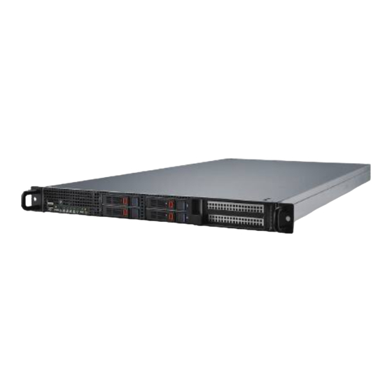
- Page 1 User Manual AGS-910 High Density 1U GPU Server, w/ up to 3 PCIe x16 FH/FL Double- depth &1 PCIe x8 FH/HL Single- depth Expansion Card...
- Page 2 No part of this manual may be reproduced, copied, translated or transmitted in any form or by any means without the prior written permission of Advantech Co., Ltd. Information provided in this manual is intended to be accurate and reliable. How- ever, Advantech Co., Ltd.
-
Page 3: Declaration Of Conformity
Whether your new Advantech equipment is destined for the labo- ratory or the factory floor, you can be assured that your product will provide the reliability and ease of operation for which the name Advantech has come to be known. -
Page 4: Safety Information
You must become familiar with the safety information in this guide before you install, operate, or service Advantech products. Machine Room Environment ... - Page 5 Adavantech, your authorized Advantech partner, or their agents. Equipment Modifications Do not make mechanical modifications to the system. Advantech is not respon- sible for the regulatory compliance of Advantech equipment that has been mod- ified. Equipment Repairs and Servicing ...
- Page 6 Xeon E5-2665/2.4GHz/8cores 115W Intel Xeon E5-2637/3.0GHz/2cores Intel Xeon E5-2643 v2/3.5GHz/6cores 130W Intel Xeon E5-2650 v2/2.6GHz/8cores Intel Xeon E5-2650L v2/1.7GHz/10cores Intel Xeon E5-2660 v2/2.2GHz/10cores Intel Xeon E5-2667 v2/3.3GHz/8cores 130W Intel Xeon E5-2670 v2/2.5GHz/10cores 115W Intel Xeon E5-2690 v2/3.0GHz/10cores 130W AGS-910 User Manual...
- Page 7 AGS-910 UL x16 riser Riser Card 9696910R10E Advantech AGS-910 LL x16 riser 9696910R30E Advantech AGS-910 LR x16 riser Power 96PSR-1K1W1U-AD 1100W power module supply 2112A Note! AGS-910 system MUST use the SSD or enterprise level SATA HDD or SAS HDD. AGS-910 User Manual...
- Page 8 It should be free of marks and scratches and in perfect working order upon receipt. When unpacking the AGS-910, check it for signs of ship- ping damage. (For example, damaged box, scratches, dents, etc.) If it is damaged or it fails to meet the specifications, notify our service department or local sales repre- sentative immediately.
-
Page 9: Table Of Contents
Chapter Chipset Software Installation Utility Before You Begin ..................72 Introduction ..................... 72 4.2.1 Main Menu .................. 72 Windows OS Driver Setup ..............73 Chapter VGA Setup ..........75 Introduction ..................... 76 Windows Series Driver Setup ..............76 AGS-910 User Manual... - Page 10 6.1.2 Features..................78 6.1.3 Installation................... 78 6.1.4 Windows Series Driver Setup (LAN)........... 79 AHCI & SATA RAID ................80 Appendix A Programming the Watchdog Timer . 81 Watchdog Timer Overview..............82 Programming the Watchdog Timer ............82 AGS-910 User Manual...
-
Page 11: Chapter 1 Overview
Chapter Overview... -
Page 12: Introduction
DDR3 1066/1333/1600/1866 MHz memory up to 128 GB. AGS-910 provides 3 x PCIe x16 slot (x16 link)* + 1 x PCIe x8 slot (x8 link)*. In addition, the AGS-910 has four Gigabit Ethernet LAN ports via four dedicated PCIe x1 gen2 bus, which offer bandwidth up to 500 MB/s, eliminating network bottlenecks. -
Page 13: System Specifications
Power 900 W @ 100 ~ 120 V 1100 W @ 200 ~ 240 V Power Connector Expansion 6 x 6 pin 12V power connector for 6 pin / 8 pin expansion card. Card power Expansion Slots AGS-910 User Manual... - Page 14 RoHS Compliant 6/6 Pb Free Operating Temperature: 0 to 40° C Non-operating Temperature: -10 to 70° C Environmental Spec. Operating Relative Humidity: 0% to 90% (non-condensing) Non-operating Relative Humidity: 5% to 95% (non-condensing) AGS-910 User Manual...
-
Page 15: System Layout, Led, Jumpers And Connectors
System Layout, LED, Jumpers and Connectors Connectors on the AGS-910 are linked to external devices such as hard disk drives. In addition, AGS-910 has a jumper that are used to clean CMOS for BIOS. The tables below list the functions of each jumper and connector. Later sections in this chapter give instructions for setting jumpers. -
Page 16: Led Definitions
Access activity Blinking HDD fail On (only work under the RAID mode) 4 Hz Blinking (only work under the RAID Identify (locate the HDD) mode) 1 Hz Blinking (only work under the RAID SATA/SAS RAID building mode) AGS-910 User Manual... -
Page 17: Jumpers
Power supply DC output ON and OK No AC power to power module 1.4.2 Jumpers Label Function Default JCMOS1 CMOS clear JME1 ME update Keep CMOS data / Disable ME update Clear CMOS data / Enable ME update AGS-910 User Manual... -
Page 18: Connectors
BP P1 ~ P2 5V power output connector for HDD back plane FP USB 1_2 USB port 3, 4 FP USB 3 USB port 5 (internal type-A, horizontal) FP USB 4 USB port 6 (internal type-A, vertical) AGS-910 User Manual... -
Page 19: Block Diagram
Block Diagram System Memory AGS-910 has eight 240-pin memory slots for DDR3 1066/1333/1600 MHz memory modules with maximum capacity of 128 GB (Maximum 16 GB for each DIMM). AGS-910 supports registered DIMMs or unbuffered DIMM with ECC / Non-ECC memory module. -
Page 20: Memory Installation Procedures
Memory Installation Procedures Single processor installed Dual processor installed (CPU0) (CPU0 & CPU1) Quantity of memory module installed DIMM A0 DIMM B0 DIMM C0 DIMM D0 DIMM E0 DIMM F0 DIMM G0 DIMM H0 AGS-910 User Manual... -
Page 21: Chapter 2 Setting Up
Chapter Setting up... -
Page 22: Before You Begin
Components and electronic circuit boards can be damaged by discharges of static electricity. Working on a system that is connected to a power supply can be extremely dangerous. Follow the guidelines below to avoid damage to AGS-910 or injury to yourself. -
Page 23: Installing Motherboard Components
This section describes how to install components on to the mainboard, including CPUs, memory modules and add on cards. 2.2.1 Removing the Chassis Cover Follow these instructions to remove AGS-910 chassis cover. Unscrew the top cover as follows. Slide the rear top cover out. AGS-910 User Manual... -
Page 24: Installing The Cpu And Heatsink
Follow the steps below to install CPUs and CPU heatsinks. Locate the CPU sockets - you must install into the CPU0 socket first. Pull the lever slightly away from the socket and then push it to a fully open posi- tion. AGS-910 User Manual... - Page 25 Push the CPU socket cover to a fully open position. Place the CPU into the socket and make sure that the gold arrow is located in the right direction. AGS-910 User Manual...
- Page 26 Take off the protection cap. Close the CPU socket cover and press the lever down to secure the CPU. AGS-910 User Manual...
- Page 27 Position the heatsink on top of the CPU and secure it with 4 screws. Repeat the procedures earlier to install the second processor and heatsink. Now follow the below image for CPU heatsink installation. AGS-910 User Manual...
-
Page 28: Installing The Memory
Align the memory module with the slot. When inserted properly, the memory slot locking levers lock automatically onto the indentations at the ends of the mod- ule. Follow the recommended memory population table to install the other memory modules. AGS-910 User Manual... -
Page 29: Installing Hard Drives
2.2.4 Installing Hard Drives The AGS-910 supports four 2.5” hard drives. Follow these instructions to install a hard drive. Press the locking lever latch and pull the locking lever open. Slide the HDD tray out. AGS-910 User Manual... - Page 30 Place a hard drive into the drive tray, then use the screws to secure the HDD. Reinsert the HDD tray into the chassis and press the locking lever to secure the tray. AGS-910 User Manual...
-
Page 31: Installing Pcie X16 Expansion Cards
Installing PCIe x16 Expansion Cards (We use PCIe x16 double-depth GPU card as sample) The AGS-910 supports three PCIe x16 expansion slots. Please follow these instructions to install the expansion cards. Unscrew the riser card cage and carefully place your fingers on the card cage holding positions. - Page 32 Release the expansion card holder. Unscrew the IO bracket from the card cage. AGS-910 User Manual...
- Page 33 Install the expansion card into the card cage. Screw the expansion card IO bracket onto the card cage. AGS-910 User Manual...
- Page 34 Move the card holder toward to the expansion card. Screw the card holder onto the expansion card. Connect the expansion card power cable to the expansion card power connec- tor. AGS-910 User Manual...
-
Page 35: Installing Pcie X8 Expansion Card
Installing PCIe x8 Expansion Card (We use PCIe x8 mini SAS to SATA RAID card as sample) The AGS-910 supports one PCIe x8 expansion slot. Please follow these instructions to install the expansion cards. Unscrew the riser card bracket and release the PCIe x8 riser card. - Page 36 Screw the expansion card onto the riser card bracket. Install the expansion card onto the riser card. AGS-910 User Manual...
- Page 37 Install the mini SAS to SATA cable into the expansion card, then make the cable pass through the plastic clip. Install the expansion card into the chassis and secure it. AGS-910 User Manual...
- Page 38 Remove the SATA / SATA SGPIO cable from the motherboard and HDD back plane. Install the SATA & SGPIO connector* into HDD back plane. AGS-910 User Manual...
-
Page 39: Rack Mounting
Please see SATA / SAS SGPIO pin header definition as below picture. Rack Mounting After installing the necessary components, the AGS-910 can be mounted in a rack using the supplied rack mounting kit. We strongly recommend that the minimum depth of cabinets is 1000mm. - Page 40 Follow these instructions to mount the AGS-910 into an industry standard 32” rack. Screws list M5 x16 M4 x9 Remove the chassis (inner) member. Pull the slide open. Then press the trigger down as shown on the drawing, and pull the chassis (inner) member out.
- Page 41 It might cause catastrophic damage to the chassis if ball retainer is not in fully open position while mounting the chassis. While you are pushing chassis back to the cabinet, you need to release the slide from locking position by pressing the trigger down. AGS-910 User Manual...
- Page 42 Fiabilité de la mise - Fiable mise à la terre de l'équipement monté en rack doit être maintenue. Une attention particulière devrait être accordée à fournir connexions autres que les connexions directes sur le circuit de branche (par exemple l'utilisation de multiprises). AGS-910 User Manual...
-
Page 43: Chapter 3 Ami Bios
Chapter AMI BIOS... -
Page 44: Introduction
The Setup program uses a number of menus for making changes and turning the special features on or off. This chapter describes the basic navigation of the AGS-910 setup screens. AMI's BIOS ROM has a built-in Setup program that allows users to modify the basic system configuration. -
Page 45: Bios Setup
System Date using the <Arrow> keys. Enter new values through the keyboard. Press the <Tab> key or the <Arrow> keys to move between fields. The date must be entered in MM/DD/YY format. The time must be entered in HH:MM:SS format. AGS-910 User Manual... -
Page 46: Advanced Bios Features Setup
3.2.2 Advanced BIOS Features Setup Select the Advanced tab from the AGS-910 setup screen to enter the Advanced BIOS setup screen. You can select any of the items in the left frame of the screen, such as CPU configuration, to go to the sub menu for that item. You can display an Advanced BIOS Setup option by highlighting it using the <Arrow>... - Page 47 Enables or disables 64-bit capability. Devices to be decoded in above 4G address space (Only if system supports 64-bit PCI decoding). PCI Latency Timer Value in units of PCI clocks for PCI device latency timer register. VGA Palette Snoop Enables or disables VGA palette register snooping. AGS-910 User Manual...
- Page 48 3.2.2.2 ACPI Settings Enable Hibernation "Enable or disable" Hibernation. ACPI Sleep State Specifies the ACPI sleep state when the system enters standby. Lock Legacy Resources "Enable" or "Disable" Lock Legacy Resources. AGS-910 User Manual...
- Page 49 3.2.2.3 Trusted Computing Security Device Support Enables or disables BIOS support for security device. Purchase Advantech LPC TPM module to enable TPM function. P/N: PCATPM- 00A1E. AGS-910 User Manual...
- Page 50 3.2.2.4 WHEA Support WHEA Support “Enable or disable” Windows Hardware Error Architecture. AGS-910 User Manual...
- Page 51 3.2.2.5 CPU Configuration Socket 0/Socket 1 CPU Information AGS-910 User Manual...
- Page 52 Set to enable or disable. DCU Streamer Prefetch Enable prefetch of next L1 data line based upon multiple loads in same cache line. DCU IP Prefetcher Enable prefetch of next L1 line based upon sequential load history. AGS-910 User Manual...
- Page 53 It does this by creating virtual machines, each running its own x86 operating system. CPU Power Management Configuration Power technology default is “Energy Efficient”. User can set “EIST”, “P-STATE”, “C3”, “C6”, “Package C State limit” under “Cus- tom” Mode. AGS-910 User Manual...
- Page 54 SATA devices are supported by controller 0 and two SATA devices are sup- ported by controller 1 when under these operating systems. – Serial-ATA Controller 1 This item appears only when SATA Mode item to [IDE Mode] is set. Set to [Enhanced] to support two SATA 3.0 Gb/s devices. AGS-910 User Manual...
- Page 55 Set to [AHCI Mode] to have the SATA hard disk drives use the AHCI (Advanced Host Controller Interface). The AHCI allows the onboard storage driver to enable advanced Serial ATA features that increase storage performance on ran- dom workloads by allowing the drive to internally optimize the order of com- mands. AGS-910 User Manual...
- Page 56 RAID Mode Set to [RAID Mode] to create a RAID configuration from the SATA hard disk drives. 3.2.2.7 Intel TXT(LT-SX) Configuration This item shows Intel trusted execution technology configuration. AGS-910 User Manual...
- Page 57 Selects the USB transfer time-out value. [1,5,10,20sec] Device Reset Time-out Selects the USB device reset time-out value. [10,20,30,40 sec] Device Power-up Delay This item appears only when Device power-up delay item is set to [manual]. AGS-910 User Manual...
- Page 58 H/W Monitor Case Open Warning Enable/Disable the Chassis Intrusion monitoring function. When enabled and the case is opened, the warning message will show in POST screen. Watchdog Timer Enable and Disable the watchdog timer function. AGS-910 User Manual...
- Page 59 ACPI OS to protect the system from overheat damage. Smart Fan Mode Configuration When set to manual mode, fan duty setting can be changed; the range is from 30%~100%, default setting is 50%. AGS-910 User Manual...
- Page 60 3.2.2.10 Super I/O Configuration Serial Port 0 Configuration AGS-910 User Manual...
- Page 61 Change Settings To select an optimal setting for serial port 0. Serial Port 1 Configuration – Serial Port “Enable” or “Disable” Serial Port 1. – Change Settings To select an optimal setting for serial port 1. AGS-910 User Manual...
- Page 62 3.2.2.11 Serial Port Console Redirection Console Redirection To “Enable or disable” console redirection feature. Console Redirection Settings AGS-910 User Manual...
- Page 63 When this mode enabled, only text will be send. This is to capture Terminal data. Options available: Enabled/Disabled. Legacy OS Redirection Resolution On Legacy OS, the number of Rows and Columns supported redirection. Options available: 80x24/80X25. Putty Keypad Select function key and keypad on putty. AGS-910 User Manual...
-
Page 64: Chipset
3.2.3 Chipset 3.2.3.1 North Bridge AGS-910 User Manual... - Page 65 Numa Enable/Disable non uniform memory access (NUMA). Patrol Scrub Enable/Disable patrol scrub feature. Demand Scrub Enable/Disable demand scrub feature. Data Scrambling Enable/Disable data scrambling. Device Tagging Enable/Disable device tagging. IOH Configuration AGS-910 User Manual...
- Page 66 IOU 1- PCIe Port Functions visible based on this setting: x4x4 PORT 1A Link Speed Select target link speed as Gen1, Gen2, Gen3 PCIE SLOT2 IOU2 - PCIe Port Functions visible based on this setting: x4x4x4x4 x4x4x8 x8x4x4 x8x8 AGS-910 User Manual...
- Page 67 Select Target Link Speed as Gen1, Gen2, Gen3. PCIE SLOT6 IOU3 - PCIe port Functions visible based on this setting : x4x4x4x4 x4x4x8 x8x4x4 x8x8 PORT 3A Link Speed Select Target Link Speed as Gen1, Gen2, Gen3. AGS-910 User Manual...
- Page 68 Intel® VT for Directed I/O Configuration – Intel VT-d Enable/Disable Intel Virtualization Technology for Directed I/O. QPI Configuration AGS-910 User Manual...
- Page 69 Select the QPI link speed as either the Fast mode or Slow Mode. – QPI Link Frequency Select Allows for selecting the QPI Link frequency. – QPI Link0s Enable/Disable QPI Link0s – QPI Link0p Enable/Disable QPI Link0p – QPI Link1 Enable/Disable QPI Link1 DIMM Information AGS-910 User Manual...
- Page 70 Specify what state to go to when power is re-applied after a power failure (G3 state). SLP_S4 Assertion Stretch Enable Enable/Disable SLP_S4 Assertion Stretch function. Onboard SATA RAID Oprom Enable/Disable onboard SATA RAID option rom if Launch Storage Oprom is enabled. AGS-910 User Manual...
- Page 71 LAN3 Controller Enable/Disable Intel I210AT Controller support. – LAN3 PXE Oprom Enable/Disable Boot option for Intel I210AT controller. – LAN4 Controller Enable/Disable Intel I210AT Controller support. – LAN4 PXE Oprom Enable/Disable Boot option for Intel I210AT controller. AGS-910 User Manual...
- Page 72 USB Configuration – All USB Devices Enable/Disable all USB devices. – EHCI Controller 1 Enable/Disable USB 2.0 (EHCI) support. – USB Port 0 ~ 5 Enable/Disable USB 2.0 port 0 ~ 5. AGS-910 User Manual...
-
Page 73: Server Management
3.2.3.3 ME Subsystem 3.2.4 Server Management AGS-910 User Manual... - Page 74 Wait for BMC counter for initialize host to BMC interfaces. The MB beep per 5 seconds to check it. BMC Self Test Log – Erase Log Erase log options. – When Log is Full Select the action to be taken when log is full. AGS-910 User Manual...
- Page 75 – When SEL is Full Choose options for reactions to a full SEL. – Log EFI Status Codes Disable the logging of EFI status codes or log only error code or only prog- ress code or both. AGS-910 User Manual...
- Page 76 BMC Network Configuration – Configuration Address Source Select to configure LAN channel parameters statically or dynamically (by BMC). Unspecified option will not modify any BMC network parameters dur- ing BIOS phase. AGS-910 User Manual...
-
Page 77: Boot
Enable/Disable quiet boot option. INT19 Trap Response BIOS reaction on INT19 trapping by option ROM: Immediate - execute the trap right away. Postponed - execute the trap during legacy boot. Boot Option Sets the system boot priorities. AGS-910 User Manual... -
Page 78: Security
3.2.6 Security AGS-910 User Manual... -
Page 79: Save & Exit
Restore Defaults Restore/Load default values for all the setup options. Save as User Defaults Save the changes done so far as user defaults. Restore User Defaults Restore the user defaults to all the setup options. AGS-910 User Manual... - Page 80 AGS-910 User Manual...
-
Page 81: Chapter 4 Chipset Software Installation Utility
Chapter Chipset Software Installation Utility... -
Page 82: Before You Begin
Before You Begin To facilitate the installation of the enhanced display drivers and utility software, read the instructions in this chapter carefully. The drivers for the AGS-910 are located on the software installation CD. Before beginning, it is important to note that most display drivers need to have the relevant software application already installed on the system prior to installing the enhanced display drivers. -
Page 83: Windows Os Driver Setup
Windows OS Driver Setup Insert the driver CD into your system's CD-ROM drive. When the folder is dis- played, move the mouse cursor over the folder "01_Intel INF". Find the execut- able in this folder, click to install the driver. AGS-910 User Manual... - Page 84 Click setup to execute program. AGS-910 User Manual...
-
Page 85: Chapter 5 Vga Setup
Chapter VGA Setup... -
Page 86: Introduction
"02_Graphic chip" folder and click the executable file to complete the installation of the drivers for OS that you need. Note! If AGS-910 carries an additional graphics card for VGA output, please set this additional graphic card as "major output" under the "Display properties" of OS. - Page 87 Chapter LAN Configuration & SATA RAID & AHCI Setup...
-
Page 88: Lan Configuration
6.1.1 Introduction The AGS-910 has four Gigabit Ethernet LAN connections via dedicated PCI Express x1 lanes: GbE LAN1 - Intel 82579LM; GbE LAN2 ~ LAN4 Intel I210AT. They offer bandwidth of up to 500 MB/sec, eliminating the bottleneck of network data flow and incorporating Gigabit Ethernet at 1000 Mbps. -
Page 89: Windows Series Driver Setup (Lan)
6.1.4 Windows Series Driver Setup (LAN) Insert the driver CD into your system's CD-ROM drive. Select folder "03_Lan chip" then click the proper Lan driver for the OS. AGS-910 User Manual... -
Page 90: Ahci & Sata Raid
AHCI & SATA RAID Intel C602J PCH chip offers SATA RAID with RAID 0, 1, 10, 5 under Windows operat- ing system. AGS-910 User Manual... -
Page 91: Appendix A Programming The Watchdog Timer
Appendix Programming the Watchdog Timer... -
Page 92: Watchdog Timer Overview
Soft Watch Dog Timer. The Soft Watch Dog will start count down. When the timer that we set to CR[E3h] is timeout , WDTRST# will issue low pulse signal. The Bank0 CR[E2h] is Watch Dog Status Register for reading. AGS-910 User Manual... - Page 93 AGS-910 User Manual...
- Page 94 No part of this publication may be reproduced in any form or by any means, electronic, photocopying, recording or otherwise, without prior written permis- sion of the publisher. All brand and product names are trademarks or registered trademarks of their respective companies. © Advantech Co., Ltd. 2014...
Need help?
Do you have a question about the AGS-910 and is the answer not in the manual?
Questions and answers