Table of Contents
Advertisement
Quick Links
Advertisement
Chapters
Table of Contents

Related Manuals for Technisonic Industries Limited TSC-4400


Summary of Contents for Technisonic Industries Limited TSC-4400
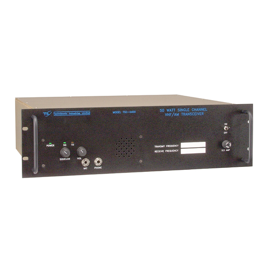
- Page 1 VHF/AM SINGLE CHANNEL 50 WATT TRANSCEIVER MODEL TSC-4400 P/N 011211-1 Installation and Operating Instructions TiL Document No. 04RE331 Rev. n/c March 2004 Technisonic Industries Limited 240 Traders Blvd., Mississauga, Ontario L4Z 1W7 Tel:(905)890-2113 Fax:(905)890-5338 web site: www.til.ca...
- Page 2 This unit contains static sensitive devices. Wear a grounded wrist strap and/or conductive gloves when handling printed circuit boards. WARRANTY INFORMATION The rack mounted Single Channel Transceiver, Model TSC-4400 is under warranty for one year from date of purchase. Failed units caused by defective parts, or workmanship should be returned to: Technisonic Industries Limited...
- Page 3 REVISIONS PAGE DESCRIPTION DATE APPROVED Complete Original release March H.D. document /2004...
-
Page 4: Table Of Contents
TABLE OF CONTENTS Paragraph Title Page SECTION 1 GENERAL DESCRIPTION Introduction ..........1-1 Description . - Page 5 TSC-4400 Configurations ........1-1...
-
Page 6: General Description
AC power or external DC power in local and remote operating modes. DESCRIPTION The TSC-4400 is a fully pre-programmable 50 Watt transceiver. It can be configured for 2 Wire and 4 Wire remote operation with a variety of remote keying methods (with 923051-1 standard card). -
Page 7: Transceiver Module
1.2.1 Transceiver Module The Single Channel Transceiver is based on Transceiver Model 90-6R/8.33. The transceiver module is a low power VHF/AM transceiver which can transmit or receive on independent, pre- programmable synthesized frequencies, with 25kHz or 8.33kHz channel spacing in the frequency range 118.000 MHz to 138.000 MHz. -
Page 8: Crystal Filter (Option 1)
Line Interface Board P/N 943180-1 Provides remote control transceiver operation on 2 wire dedicated 600 ohm lines utilizing the EIA multi-tone keying format found in the Land Mobile Industry. A high level 2175 tone followed by a 1950 Hz guard tone and then a low level 2175 Hz continuous tone is utilized to key the transceiver. -
Page 9: Ac And Dc Operation
1.3.1 AC and DC Operation The unit can be operated by external 120/240 VAC or external 50 VDC & 12 VDC. AC OPERATION - During AC operation, the unit can charge and trickle charge external batteries via the external connectors mounted on the rear panel of the unit. Refer to section 3 for remote connector pin details regarding DC operation. -
Page 10: Tsc-4400 Leading Particulars
TABLE 1-2 TSC-4400 LEADING PARTICULARS POWER REQUIREMENTS: AC Input Voltage/Current ....100 to 260 VAC @ 3.5 Amp DC Input Voltage/Current ....50 VDC Nominal @ 5.0 Amp . - Page 11 TABLE 1-2 TSC-4400 LEADING PARTICULARS (Continued) TRANSCEIVER MODULE: Dimensions & Weight: Width ......... 216 mm (8.5 in) MAX Height .
-
Page 12: Preparation For Use And Storage
SECTION 2 PREPARATION FOR USE AND STORAGE INTRODUCTION This section provides the information required for custom configuration and storage of the Single Channel Transceiver. Custom system configuration includes customizing remote control board functions, and Transmit/Receive frequency selection. CAUTION: Antenna must be connected to transceiver before transmitting or permanent damage to the output stage may occur. - Page 13 Figure 2-1Single Channel Transceiver - Internal View...
-
Page 14: Remove/Replace Control Board
Move the transceiver module slightly back from the front panel and disconnect the flat cable connecting the front panel assembly to the transceiver module, audio interface board A3. The connector is located on the A3 board. Lift transceiver module clear of chassis. REPLACEMENT Position the transceiver module into the chassis. - Page 15 Programming Interface Board with Crystal Filter Option Figure 2-2...
-
Page 16: Remove/Replace Crystal Filter Board, P/N 923069
CHANNEL FREQUENCY PROGRAMMING 2.3.1 Introduction Transceiver Model TSC-4400, as shipped from the factory, is preprogrammed with a test frequency. Before programming a new frequency, perform an operational check. If there is any deficiency or equipment malfunction, the transceiver is to be returned to the manufacturer, Technisonic Industries Limited, under warranty. - Page 17 A standard 9 pin serial cable must be temporarily connected between the front panel DB-9 connector on the transceiver and the computer serial port. The transceiver is capable of 25 kHz spacing (wide band) and 8.33 kHz spacing (narrow band) channels. The frequency entered will determine whether the channel will be wide or narrow mode, based on the Combined 8.33 kHz/25 kHz ICAO Frequency-Channel Pairing Plan.
-
Page 18: Programming A Frequency
2.3.4 Programming a Frequency Having ascertained the desired operating frequency, continue as follows: Run the TDP-90 program on the computer. Click on the Data pull-down list and select the serial port to which the transceiver is connected. Set the program for 1 channel. Turn on power to the transceiver. -
Page 19: Remote Operation Setup
REMOTE OPERATION SETUP The Procedures listed below enable the user to custom configure the unit for external remote control hardware. Refer to Table 2-3 for connector pin details on Remote Control D Connector located at rear of Single Channel Transceiver. Position Jumpers on Control board as indicated in Table 2-4 or Table 2-5 as required. -
Page 20: Remote Control Board P/N 923051-1
2.4.1 Two/Four Wire Remote Control Board P/N 923051-1 Provides remote control base station operation on 2 wire or 4 wire, 600 ohm lines. This board can be configured to key the transmitter using a 2175 Hz tone (2380 Hz upon request), plus/minus DC Voltages, ground keying and internal or external current loop keying. -
Page 21: Remote Control Board P/N 943180-1 Settings
2.4.2 Two Wire Line Interface Board P/N 943180-1 Provides remote control Base Station operation on 2 wire 600 ohm lines. Two wire Line Interface board with EIA multi-tone, standard 2175Hz continuous tone, DC keying of ground keying over audio lines. The multi-tone keying format consists of a high level 2175 tone followed by a 1950 Hz guard tone and then a low level 2175 Hz continuous tone is utilized to key the transceiver. - Page 22 Control Configuration for 2/4 Wire (+/-)DC/Ground/Tone/ (Current Loop) Keying Control Board. Assembly #: 923051 Tx Audio SW2: Selects either Local (-25 dBm sensitivity; or Land Line Current increases clockwise). Loop Keying. R10: 2 Wire Rx Balance @ 600O Selects DC or Current (1mV RF @ 1KHz, 30% Mod.) Loop Keying operation.
-
Page 23: Remote Control Board P/N 943180-1
Control Configuration for Multi-Tone Control Board. Assembly #: 943180 Tx audio level adjustment (-25 dBm). J1: Standard or EIA R24: Keying Tone Attenuator. Keying tone protocol. R26: 1950 Hz tone level adjustment Selects Tone and/or Current Loop/ R41: 2175 Hz tone level adjustment Ground Keying enable or disable Rx Audio level adjustment. -
Page 24: Optional Loudspeaker, Headphone Installation
OPTIONAL LOUDSPEAKER, HEADPHONE INSTALLATION Provision is made for connection of an external loudspeaker or headphone to the SPEAKER/PHONE jack of the transceiver, as shown in Figure 3-1. 2.5.1 External Loudspeaker When an external loudspeaker is to be installed, an 8-ohm nominal impedance loudspeaker should be used. - Page 25 Figure 2-5Transceiver Adjustments and Settings 2-14...
-
Page 26: Introduction
Operating instructions for transmit/receive and the special functions are also included. INSTALLATION The TSC-4400 Transceiver is designed to be mounted in a 19 inch rack. An AC Line cord P/N 927002-1 is supplied for connection to AC Power. A 9 Pin connector (mates with Positronic... -
Page 27: Single Channel Transceiver Controls And Indicators
Figure 3-1 Single Channel Transceiver Controls and Indicators... - Page 28 TABLE 3-1 OPERATOR'S SWITCHES, CONTROLS AND INDICATORS Item SWITCHES CONTROLS & FUNCTIONAL DESCRIPTION INDICATORS POWER ON/OFF A toggle switch applies the AC power to the power supply and the SWITCH DC voltage to the transceiver. The transceiver is switched to ON in the toggle UP position the transceiver is switched OFF in the toggle DOWN position.
- Page 29 TABLE 3-1 OPERATOR'S SWITCHES, CONTROLS AND INDICATORS (Continued) Item SWITCHES CONTROLS & FUNCTIONAL DESCRIPTION INDICATORS RX LABEL Indicates the frequency programmed for receive. LOUDSPEAKER An 8-ohm internal speaker reproduces the receiver audio output. The audio line is disconnected from the internal loudspeaker when transceiver operated mode...
-
Page 30: Transmitter Operation (Local Mode)
OPERATING INSTRUCTIONS NOTE Refer to appropriate Operating Instructions for use with Remote Control Unit. NOTE The following operating procedures are intended specifically for Local Operation. Ensure that the microphone connector is connected to the MIC/PTT connector of the transceiver. Set the SQUELCH control in the fully counter-clockwise (CCW) position. Set the VOLUME control in the 12 o'clock centre position. -
Page 31: Receiver Operation (Local Mode)
The transceiver is now operating in the receive mode. Verify that the Tx ON amber LED is OFF. 3.4.2 Receiver Operation (Local Mode) To operate the transceiver in the receive mode, proceed as follows: Ensure that the PRESS-TO-TALK switch on the microphone is NOT depressed, and verify that the Tx ON amber LED is OFF. -
Page 32: Switching Off
NOTE When an external loudspeaker or headset is connected to the SPEAKER/PHONE jack of the transceiver, the internal loudspeaker is automatically disconnected. The VOLUME control will now control the audio level applied to the external loudspeaker or headset, as applicable. 3.4.3 Switching OFF To switch off the transceiver: Set the POWER ON/OFF on transceiver to switch to OFF. - Page 33 Section 3 Addendum A Til Document No. 04RE332...
-
Page 34: Operating Instructions
United States Government, this document may not in whole or in part, be duplicated or disclosed or used for manufacture of the part disclosed herein, without the prior permission of Technisonic Industries Ltd. TiL TDP-90 Data Programming Software for the TSC-4400 Transceiver Installation and Operating Instructions TiL Document No. - Page 35 TABLE OF CONTENTS Paragraph Title Page SECTION 1 GENERAL DESCRIPTION Introduction ..........1-1 Description .
-
Page 36: Title Page
LIST OF ILLUSTRATIONS Figure No. Title Page 2.1.1 Setup Extraction Dialog ........2-1 2.1.2 Welcome Dialog . - Page 37 Copyright and Trademark acknowledgement Microsoft, Windows 95, Windows 98, Windows NT, Windows 2000, DCOM, and Internet Explorer are registered trademarks of Microsoft Corporation. DPL is a registered trademark of Motorola Inc. Adobe, Adobe Acrobat, and Adobe Acrobat Reader are registered trademark of Adobe Systems Inc.
-
Page 38: General Description
SECTION 1 GENERAL DESCRIPTION INTRODUCTION This publication provides operating and installation information on the TiL TDP-90 Programming Software for 8.33 kHz AM series transceivers. The TDP software allows a standard PC to retrieve data from a connected 8.33kHz AM series transceiver, for editing, storing, and sharing with other 8.33 kHz AM series transceivers. -
Page 39: Installation Instructions
SECTION 2 INSTALLATION INSTRUCTIONS SOFTWARE INSTALLATION Before the TDP software can be installed, all of the minimum computer system requirements outlined in the previous section must be met, otherwise difficulty may be encountered during installation or operation the software. The installation procedures outlined in this document assume some basic working knowledge of at least one of Microsoft's Windows 95/98/NT/2000 operating systems. - Page 40 Figure 2.1.3 - License Agreement In order to Install the TDP-90 Software onto your computer, you must agree to the terms of the license agreement, and confirm so by clicking on OK in the License dialog box. Figure 2.1.4 - Program Installation Dialog...
-
Page 41: Windows 95
2.1.1 Windows 95 If your computer does not have Microsoft Internet Explorer 5.0 or any other Microsoft application, no later than mid 1998 installed, then it is possible that certain essential system files are outdated. If these system files are outdated your system will not meet the minimum requirements for installing and operating a large variety of new software including the TDP software. -
Page 42: Windows 98 / Windows 2000
2.1.2 Windows 98 / Windows 2000 Windows 98 comes pre installed with Internet Explorer 5.0 embedded into the operating system. As a result, the operating system as a whole meets the requirements for the installation and operation of the TDP software. To install the TDP software, locate the TDP90_Install.exe file on the CD-ROM using Windows Explorer. - Page 43 After setup finishes unpacking the software, a dialog box will pop up with the option to continue (by clicking on the Next> button see Figure 2.1.4), exit the setup, or at this time you may choose an alternate location for the installation. If you have no objections to the default location just click on the Next>...
-
Page 44: Hardware Installation
HARDWARE INSTALLATION Rack Mount Transceiver: Plug the female end of a 9 pin serial cable into the 9 pin D connector on the front panel of the unit. Connect the other end of the serial cable to an available Serial (COM) Port on your PC. -
Page 45: Operating Instructions
The number of channels in the Frequency editing window changes accordingly. Select “1 Channel TxRx” for the TSC-4400. The frequency, as displayed in the Frequency editing window, can be changed by clicking on the channel window and entering the frequency. -
Page 46: Pull Down Menus
PULL DOWN MENUS The TDP-90 program has several functions available through the use of pull-down menus. Through these menus, you can invoke file functions, print the channel list, initiate communications with a connected TFM-90 and quit the TDP software. 3.3.1 File Menu Figure 3.3.1 - File Menu Open will allow you to select and load and existing file that was previously saved on disk. -
Page 47: Data Transfer Menu
The COM port setting is automatically saved. The next time the TDP-90 software is executed, the previously selected COM port will be used. NOTE: ** The TDP-90 software assumes you have an available and properly configured COM port, and assumes that a TSC-4400 transceiver is connected. **... -
Page 48: Help Menu
3.3.3 Help Menu Figure 3.3.3 - Help Menu TDP-90-6R Help Contents will start the Windows Help dialog for the TDP-90 software. Here, you will find hardware connection and operating information as well as troubleshooting tips and answers to some Frequently Asked Questions. About displays Technisonic company and contact information as well as the revision number of the TDP software in the “Terminal window”... -
Page 49: Channel Selection
Figure 3.3.4.1 - Single channel Figure 3.3.4.2 - Six channels The x Channel(s) pull-down tab allows you to select for single or six channel 8.33 kHz AM transceiver use. The frequency editing window changes accordingly. Select “1 Channel TX/RX” for the TSC-4400. -
Page 50: Sample Upload And Download
SAMPLE UPLOAD AND DOWNLOAD 1. Connect the computer to the transceiver and apply power as described in section 2.2. 2. Run the TDP-90 program on the computer. 3. Click on the Data pull-down list and select the serial port to which the transceiver is connected.
Need help?
Do you have a question about the TSC-4400 and is the answer not in the manual?
Questions and answers