Table of Contents
Advertisement
Quick Links
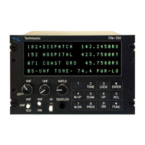
MODEL TFM-550
Airborne UHF and VHF High/Low band FM Transceiver
Technisonic Multi-Band VHF Lo/VHF Hi and UHF AirborneTransceiver
The Technisonic TFM-550 Multi-Band airborne VHF/UHF FM transceiver utilizes state of the art frequency synthesis techniques to
provide FM communications on every currently available channel within the General Radio Service VHF/FM Low Band, VHF/FM
High Band and UHF/FM Band. This transceiver covers VHF Low Band from 30 to 50 MHz in 2.5 KHz steps, VHF High Band from
138 to 174 MHz in 2.5 KHz increments and UHF from 403 to 512 MHz also in 2.5 KHz steps. Operating frequencies and other
related data are presented on a 96 character, four line LED matrix display, which is available in either red or green.
The TFM-550 can be installed to operate in "Single Mode" to function as a multi-band transceiver operating in VHF Lo, VHF Hi or
UHF bands with combined audio run through a single audio controller FM input. In this mode, the band select switch is positioned
by the operator to select one of the three bands which are accessed one at a time. Combined audio and transmit control are
available at J101 (15 pin connector) at the rear of the transceiver. Alternately, the TFM-550 can function in "Dual Mode" and be
installed to two FM positions (typically FM1 and FM2) on the audio controller, allowing for simultaneous operation on UHF and
either VHF Low or VHF High Band. In this mode, VHF Hi and VHF Lo audio are combined and output to a single audio controller
FM input. The front panel band select switch provides for VHF-Hi or VHF Lo transmitter selection. VHF Hi and VHF Lo audio and
transmit control functions are available at J102 (9 pin connector) at the rear of the transceiver. UHF receive and transmit
functions are totally independent and controlled via the second audio controller position allowing for simultaneous VHF (Hi or Lo)
and UHF operation. Additionally, the TFM-550 can operate as a VHF/UHF cross band repeater. The cross band function is front
panel controlled and requires only 2 key stokes to enable or disable. All data entry and control commands are entered via an
enhanced 12 button keypad situated on the face panel.
The TFM-550 can be operated in the Direct Entry or Simplex mode by simply keying in the desired operating frequency. It can
also function without restriction on any split frequency pair within any of it's three bands. This unit features 600 preset memory
positions (200 VHF Lo, 200 VHF Hi and 200 UHF) each capable of storing a receive frequency, a transmit frequency, a separate
CTCSS tone for each receive and transmit frequency, an alpha numeric identifier for each channel and a DPL or DCS coded
squelch identifier for each channel. The TFM-550 provides for either 25 kHz wide band or 12.5 kHz narrow band operation on any
or all of it's 600 preset channels. An upload/download function allows the operator to download channel information from a PC, or
upload stored data from the transceiver to a PC. Supporting software is supplied with each unit. Information stored in the
transceiver's memory is available for instant recall by keypad entry or, by pressing the M.UP or M.DOWN button which allows the
operator to scroll through all preset channels. The TFM-550 transceiver also features a DTMF encoder for signaling during
transmit, and a scan function which will scan any or all of the frequencies stored in up to five scan lists. Additionally, a remote
control head is offered (RC-550) which provides for slaved operation of the main transceiver from a remote location, allowing for a
second position in the aircraft to exercise frequency control. VHF Low band, VHF High Band and UHF operating frequencies as
well as the Direct/Repeat function can be controlled from the "remote" position. Active frequency for all three bands is displayed
on both remote and local displays.
The TFM-550 transceiver is panel mounted (Dzus) and completely self contained in a 8.0 x 3.75 x 5.75 inch chassis weighing just
5.0 pounds. Front panel controls are UHF for UHF audio level; VHF for VHF High Band audio level and VHFLO for VHF Low
Band audio level. The VHF/UHF/VLO band switch enables selection of the desired band as well as providing for manual
programming, a VHF/PRI select switch provides for a VHF priority channel, and a HI/LO switch controls transmitter power output.
Twenty eight (28) volt DC backlighting is standard, (5 Volt AC is optional) and controlled by the aircraft dimmer bus. Display
brightness is controlled from the front panel keypad. RC-550 "remote control" access is via a 9 pin connector (J102) located on
the rear panel of the TFM-550 transceiver. External access for mic level adjust (sidetone is software controlled and operator
adjustable) provides for easy installation and setup for optimum performance. The small size and light weight (5.0 lbs., 2.3 Kg) of
the TFM-550 Multi- Band transceiver makes this radio ideally suited to helicopter installations. Technisonic FM radios are
compliant with RTCA DO-160C categories relating to Vibration, Overpressure, Humidity, Temperature and Altitude, Magnetic
Effect, Power Input, Voltage Spike, Decompression, and RF Emission (including DO-160C, Section 21, Category Z).
Advertisement
Table of Contents

Related Manuals for Technisonic Industries Limited TFM-550


Summary of Contents for Technisonic Industries Limited TFM-550
- Page 1 96 character, four line LED matrix display, which is available in either red or green. The TFM-550 can be installed to operate in “Single Mode” to function as a multi-band transceiver operating in VHF Lo, VHF Hi or UHF bands with combined audio run through a single audio controller FM input.
- Page 2 TFM-550 General Specifications General Active frequency coverage 30.000 to 50.00 MHz, 138.000 to 174.000 MHz and 403.000 to 512.000 MHz Tuning increments 2.5 KHz, all three bands Operating mode F3E Simplex or Semi-Duplex Memory positions 600 Channels total (200 each band) Dimensions Approx.
- Page 3 MULTIBAND FM AIRBORNE TRANSCEIVER Installation and Operating Instructions TiL Document No. 99RE262 Rev. A Issue 10 AUGUST 2010 Technisonic Industries Limited 240 Traders Boulevard, Mississauga, Ontario L4Z 1W7 Tel: (905) 890-2113 Fax: (905) 890-5338 www.til.ca Copyright by Technisonic Industries Limited. All rights reserved.
- Page 4 USA after this date will no longer support wide band operation on those bands. VHF low band is not affected. Channels programmed by MultiTDP software on VHF and UHF to wide band will automatically change to narrow band when loaded into the TFM-550.
- Page 5 REVISION HISTORY [ 99RE262 ] SECTION EDITED DESCRIPTION DATE - PAGE - 99RE262 CR 08194 No change to fit, form or function. Grammar and spelling check was done, corrected typos, Rev A Overall etc. as needed or found. Issue 4 A-Page: Added NOTICE regarding new address change that may appear different throughout this manual.
- Page 7 Operation of this equipment in a residential area is likely to cause harmful interference in which case the user will be required to correct the interference at his/her own expense. Do not use the TFM-550 in the frequency band 406.0 MHz – 406.1 MHz. This frequency band reserved for distress beacons.
- Page 8 Summary of DO-160C Environmental Testing Summary of DO-160C Environmental Testing for Technisonic Model TFM-550, Low-band VHF, High-band VHF and UHF Transceiver: Conditions Section Description of Conducted Tests Temperature and Altitude Equipment tested to categories B2 and D1. Vibration Equipment is tested without shock mounts to categories B, M and N.
-
Page 9: Table Of Contents
3.7.8 MEMORY UP/MEMORY DOWN ................3.7.9 DATA INPUT ..................... INTERNAL PROGRAMMING ENABLE/DISABLE JUMPER .......... TRANSMITTER POWER ADJUSTMENTS ............... 3.10 TRANSMITTER MICROPHONE LEVEL ADJUSTMENT ..........3.11 SQUELCH ADJUSTMENT ................... 3.12 TRANSMITTER DEVIATION ADJUSTMENT ............TFM-550 Installation & Operating Instructions TiL 99RE262 Rev A Issue 8... - Page 10 FIGURE TITLE PAGE TFM-550 OPERATOR'S SWITCHES AND CONTROLS ..........TFM-550 TRANSCEIVER PC UP/DOWNLOAD CABLE - WIRING DIAGRAM ....TRANSCEIVER MOUNTED VIEW OF A 15 PIN FEMALE & 9-PIN MALE CONNECTOR .. 3.1A OUTLINE DRAWING FOR MODEL TFM-550 TRANSCEIVER ........3.1B LOW PASS FILTER OUTLINE DRAWING AND INSTALLATION DETAIL ......
-
Page 11: General Description
138-150 MHz portion of the VHF band. If the TFM-550 transceiver is used in CANADA, VHF operation is restricted to the following sub bands: 138-144, 148-148.99, 149.005- 150.005 and 150.05-174 MHz. - Page 12 Ω 2.5 Watts min. into 4 Back Lighting: 28 Volts (standard) or 5 Volts (specify) Display Colour: Green (standard) or Red (specify) DPL is a trademark of Motorola Corporation TFM-550 Installation & Operating Instructions TiL 99RE262 Rev A Issue 9...
- Page 13 ±6 kHz Hum and Noise Better than 40 dB Audio Distortion less than 5% Antenna Conducted Emission less than -70 dBm VHF LOW RECEIVER All specifications identical to VHF receiver TFM-550 Installation & Operating Instructions TiL 99RE262 Rev A Issue 9...
- Page 14 -60 dB below carrier level FM Hum And Noise -40 dB Audio Input 50 mV at 2.5 kHz into Ω input circuit for ±3.5kHz deviation, adjust. Audio Distortion Less than 5% TFM-550 Installation & Operating Instructions TiL 99RE262 Rev A Issue 9...
-
Page 15: Features
If set to ON, the UHF band is operated independently from the 2 VHF bands. (Example: UHF audio separately available on 9 pin connector). The radio is shipped with this feature OFF. TFM-550 Installation & Operating Instructions TiL 99RE262 Rev A Issue 9... -
Page 16: Tfm-550 Operator's Switches And Controls
NOTE: The sidetone level must be set every time you go through the configuration menu since it takes the setting of the volume knob regardless of whether you set it or not. FIGURE 2.1 TFM-550 Operator's Switches and Controls TFM-550 Installation & Operating Instructions TiL 99RE262 Rev A Issue 9... - Page 17 This will cause the transceiver to revert back to the normal operating mode and communications with the caller can proceed in the usual fashion. Pressing the FUNC key has the same effect. TFM-550 Installation & Operating Instructions TiL 99RE262 Rev A Issue 9...
-
Page 18: Programming Instructions
PRIORITY SCANNING, SELECTIVE MEMORY SCANNING AND SCAN LISTS Instead of breaking up the 200 channels into blocks for scanning, the TFM-550 has 5 scan lists per band (VHF high and UHF only). Any of the 200 channels can be assigned to any one or more of these 5 scan lists. -
Page 19: Scanning Function
UP to transmit on 152.555 MHz. To return to the split pair condition, you must recall the memory channel again. This is quickly done by pressing M.UP for one step up, then back down one step with the M.DN key. TFM-550 Installation & Operating Instructions TiL 99RE262 Rev A Issue 9... -
Page 20: Keyboard Lockout Function
See Table 2.2 for a list of all usable and unique octal 3 digit DPL/DCS codes. 8. Press ENTER. "TX DPL" appears on the display. Repeat step 6. TFM-550 Installation & Operating Instructions TiL 99RE262 Rev A Issue 9... - Page 21 526* 036* 212* 255* 325* 455* 145* 462* 225* 332* 050* TABLE 2.2 Usable and unique octal 3 digit DPL/DCS NOTE: * indicates GE Digital Coded Squelch (DCS) Code TFM-550 Installation & Operating Instructions TiL 99RE262 Rev A Issue 9...
-
Page 22: Cross Band Repeat
2.13 CROSS BAND REPEAT The TFM-550 can act as a cross band repeater between VHF (high band only) and UHF. To enter repeat mode, press FUNC and then 9. The status line will show REPEAT instead of the band switch selection. When a signal is received on one of the bands, the audio is routed to the transmitter of the other band. -
Page 23: Tfm-550 Transceiver Pc Up/Download Cable - Wiring Diagram
TFM-550 Upload/Download Programming Cable P/N 993390-1 Wiring Diagram FIGURE 2.2 TFM-550 Transceiver PC Up/Download Cable - wiring diagram NOTE: If your serial port is a 9 pin connector instead of the 25 pin, use a female 9 pin D connector, connecting:... - Page 24 TECHNISONIC INDUSTRIES LIMITED www.til.ca This page left intentionally blank. TFM-550 Installation & Operating Instructions TiL 99RE262 Rev A Issue 9 2-10...
-
Page 25: Installation Instructions
15 pin D connector and the VHF high band BNC connector is below the 9 pin D. If an external antenna tuner (ATU) is to be used, the ATC-550 (P/N 991102-1) will have to be utilized to control it. The ATC-550 is an external box to the TFM-550. See Figure 3.1b. INSTALLATION - PIN LOCATIONS AND CONNECTIONS The pin numbers and locations for the 15 pin and 9 pin Cannon D located on the rear of the TFM-550 transceiver are shown below. - Page 26 TECHNISONIC INDUSTRIES LIMITED www.til.ca FIGURE 3.1a Outline Drawing for Model TFM-550 Transceiver TFM-550 Installation & Operating Instructions TiL 99RE262 Rev A Issue 9...
- Page 27 TECHNISONIC INDUSTRIES LIMITED www.til.ca FIGURE 3.1b Low Pass Filter Outline Drawing and Installation Detail TFM-550 Installation & Operating Instructions TiL 99RE262 Rev A Issue 9...
-
Page 28: Main Power +28Vdc
Reset Background Debug Signal Ground Programming Voltage In Serial Data Out Serial Data In Mic Signal Input 2 TABLE 3.2 Wire connections on a 9 Pin MALE D Connector TFM-550 Installation & Operating Instructions TiL 99RE262 Rev A Issue 9... -
Page 29: Wiring Connections For The Tfm-550 Transceiver
TECHNISONIC INDUSTRIES LIMITED www.til.ca Figure 3.2 Wiring connections for the TFM-550 Transceiver. TFM-550 Installation & Operating Instructions TiL 99RE262 Rev A Issue 9... -
Page 30: Main Ground
WIRING INSTRUCTIONS Figure 3.2 shows all required connections and recommended wire sizes for the TFM-550 Transceiver. If problems with the correct operation of the UHF Transmit function of a TFM- 550 are encountered on a specific airframe, a DC power line filter may be required. Typical problems encountered are that UHF will not transmit on high power or will not open a repeater when using a CTCSS transmit tone. -
Page 31: Data Input
Data communications equipment requiring direct access to the modulator and discriminator can be connected via pins 2 and 11. Data cannot be transmitted in CANADA unless equipment is approved for use with the TFM-550 by the communications regulatory authority. INTERNAL PROGRAMMING AND GUARD ENABLE/DISABLE JUMPER The programming and direct frequency entry modes can be disabled by removing the internal enable/disable jumper strap from pins 1 and 2 of J10. -
Page 32: Transmitter Power Adjustments
LED is on. Verify the squelch opens at the desired level. 3. If not, re-adjust receiver squelch potentiometer through the access hole located on the bottom of the transceiver chassis (see Figure 3.5). TFM-550 Installation & Operating Instructions TiL 99RE262 Rev A Issue 9... -
Page 33: External Adjustment Access Holes
TECHNISONIC INDUSTRIES LIMITED www.til.ca FIGURE 3.4 External Adjustment Access Holes TFM-550 Installation & Operating Instructions TiL 99RE262 Rev A Issue 9... -
Page 34: Transmitter Deviation Adjustment
30.000 MHz, and 50.000 MHz. Re-adjust R21 or R16 as required, if the deviation exceeds ±5 kHz or ±2.5 kHz, respectively. 6. Replace the top cover. TFM-550 Installation & Operating Instructions TiL 99RE262 Rev A Issue 9 3-10... -
Page 35: Deviation Adjustment Potentiometer Location
VHF Receiver/Transmitter PCB Module Notes: R30 is for 25 kHz (wideband) Deviation Adjustment R76 is for 12.5 kHz (narrowband) Deviation Adjustment FIGURE 3.5 Deviation Adjustment Potentiometer Location TFM-550 Installation & Operating Instructions TiL 99RE262 Rev A Issue 9 3-11... -
Page 36: Deviation Adjustment Potentiometer Location
UHF Receiver/Transmitter PCB Module Notes: R11 is for 25 kHz (wideband) Deviation Adjustment R102 is for 12.5 kHz (narrowband) Deviation Adjustment FIGURE 3.6 Deviation Adjustment Potentiometer Location TFM-550 Installation & Operating Instructions TiL 99RE262 Rev A Issue 9 3-12... -
Page 37: Vhf Low Deviation Adjustment Potentiometer Location
VHF LOW Band Receiver/Transmitter PCB Module Notes: R21 is for 25 kHz (wideband) Deviation Adjustment R16 is for 12.5 kHz (narrowband) Deviation Adjustment FIGURE 3.7 VHF LOW Deviation Adjustment Potentiometer Location TFM-550 Installation & Operating Instructions TiL 99RE262 Rev A Issue 9 3-13... - Page 38 TECHNISONIC INDUSTRIES LIMITED www.til.ca This page left intentionally blank. TFM-550 Installation & Operating Instructions TiL 99RE262 Rev A Issue 9 3-14...
- Page 39 POST INSTALLATION EMI TEST PURPOSE The purpose of this test is to identify any interference that the TFM-550 may cause with existing aircraft systems. As the TFM-550 installation may include the ATC-550 antenna tuner controller, this test, as required, will also identify any interference caused by the ATC- 550.
- Page 40 For example, it is permissible for a VFR certified GPS to lose navigation capability while the TFM-550 unit is transmitting, providing that it recovers properly and promptly. It is not permissible for an IFR Approach certified GPS to be affected in the same way.
- Page 41 Determine if the image frequency for the VHF Comm falls within the range of the TFM-550. If so, select a set of frequencies that will cause the TFM-550 to be set as close as possible to the image frequency. Any one of the many possible sets will suffice. Record those values in the spaces provided in the following chart.
- Page 42 TECHNISONIC INDUSTRIES LIMITED www.til.ca FREQUENCIES RESULTS VHF #2 TFM-550 PASS FAIL 135.975 121.15 157.5 131.25 157.5 Image: NOTES: TFM-550 Installation & Operating Instructions TiL 99RE262 Rev A Issue 9...
- Page 43 Determine if the image frequency for the VOR/ILS Nav falls within the range of the TFM- 550. If so, select two sets of frequencies that will cause the TFM-550 to be set as close as possible to the image frequency. Choose one set in the localizer frequency range and one in the VOR frequency range.
- Page 44 TECHNISONIC INDUSTRIES LIMITED www.til.ca FREQUENCIES RESULTS VOR/ILS #2 TFM-550 PASS FAIL 108.1 36.0325 108.1 162.15 Image: NOTES: TFM-550 Installation & Operating Instructions TiL 99RE262 Rev A Issue 9...
- Page 45 ILS to be used. Divide the glide slope frequency by 2 and program into the TFM-550. Fly the aircraft to intercept the localizer and glide slope (both needles centered) at 26 nm from the runway. Transmit on the TFM-550 for 10 seconds and watch for any deflections or flags.
- Page 46 334.7 (108.1) 33.47 334.7 (108.1) 167.35 NOTES: Operate the TFM-550 transmitter on the following frequency for at least 20 seconds. Observe the Transponder for any spurious replies or loss of reply to test set. FREQUENCIES TRANSPONDER #1 TRANSPONDER #2 TFM-550...
- Page 47 TECHNISONIC INDUSTRIES LIMITED www.til.ca Modulate the TFM-550 transmitter on the following frequencies for at least 20 seconds. Observe the DME displays. Look for loss of distance information on the display. FREQUENCIES RESULTS DME 1 TFM-550 PASS FAIL 978 (108.0) 1020 (112.1)
- Page 48 * While turning the ATC-550 on and off as often as required, listen for any noise or detected audio signals on the HF receiver audio. FREQUENCIES RESULTS #1 HF #1 PASS FAIL 16 MHz FREQUENCIES TRANSPONDER #1 HF #2 PASS FAIL 16 MHz NOTES: TFM-550 Installation & Operating Instructions TiL 99RE262 Rev A Issue 9 A-10...
- Page 49 Observations: Perform a coupled ILS approach to the aircraft's certified limits. Modulate the TFM-550 transmitter on the above frequencies for at least 20 seconds. Observe any effect on the autopilot. Repeat for second flight director/autopilot if equipped.
- Page 50 VOR/LOC 1&2 (High Band) Compass Directional Gyro Fuel Pressure Oil Temp Amps Bus Voltage Fuel % Torque % Annunciators Digital Clock Oil Pressure DME 1&2 (Low Band and Mid Band) TFM-550 Installation & Operating Instructions TiL 99RE262 Rev A Issue 9 A-12...
- Page 51 TECHNISONIC INDUSTRIES LIMITED www.til.ca NOTES: TFM-550 Installation & Operating Instructions TiL 99RE262 Rev A Issue 9 A-13...
- Page 52 Tel: (905) 890-2113 Fax: (905) 890-5338 IMPORTANT WARRANTY All communication equipment manufactured by Technisonic Industries Limited is warranted to be free of defects in Material or Workmanship under normal use for a period of one year from Date of Purchase by the end user.
Need help?
Do you have a question about the TFM-550 and is the answer not in the manual?
Questions and answers