Table of Contents
Advertisement
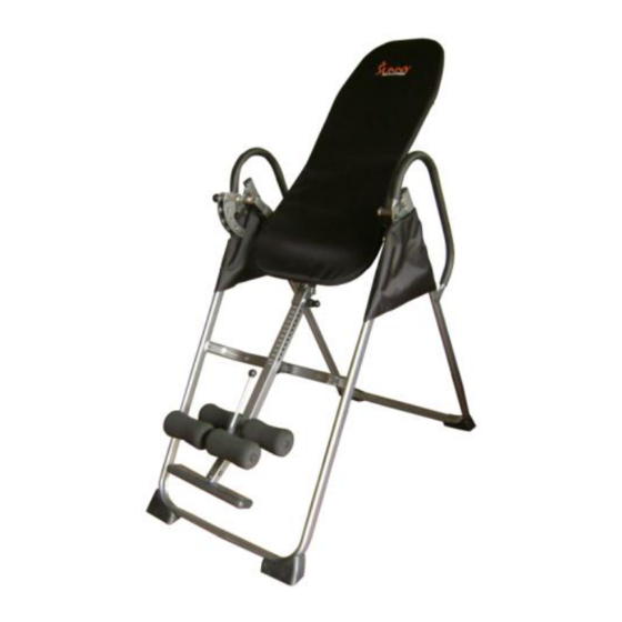
Deluxe Inversion Table
SF-1201
Take a few moments to familiarize yourself with the specific parts and hardware included with your
product. Make sure all the parts and hardware are included in the carton and examine them for any
damage that may have occurred in transport. Some parts may be pre-assembled and pre-installed.
Photo may differ from actual product
1
Owner's Manual
Advertisement
Table of Contents

Subscribe to Our Youtube Channel
Related Manuals for Sunny SF-1201


Summary of Contents for Sunny SF-1201
- Page 1 Deluxe Inversion Table SF-1201 Take a few moments to familiarize yourself with the specific parts and hardware included with your product. Make sure all the parts and hardware are included in the carton and examine them for any damage that may have occurred in transport. Some parts may be pre-assembled and pre-installed.
- Page 2 WARNING • Do not use this inversion table without approval from your physician. • Read all instructions carefully before using. • Leave adequate space to properly invert. • Tighten all bolts before using equipment. • Do not let children use the inversion table unsupervised.
-
Page 3: Exploded View
Exploded View... - Page 4 Hardware Bag Packing List Hex Head Bolt M8*25 Hex Head Bolt M8*45 Washer M8 Lock Nut M8 Ball Pin- φ8*72.5 Screw 6*25 Screw 6*20 Washer M6 Ball Pin- φ8*53 Hex Head Bolt M8*21 Hex Head Bolt M8*40 Hex Head Bolt M8*38 Tools...
-
Page 5: Parts List
Parts List Part # Description Quantity Front U-Frame Rear U-Frame Adjustment Boom Bed Frame Pivot Arm Adjustable Instep Frame Foam Leg Roller Left Folding Arm Right Folding Arm Leg Tube Hex Head Bolt 8*25mm Hex Head Bolt 8*45mm Hex Head Bolt 6*40 Washer M8 Left Foot Cap Lock Nut M8... -
Page 6: Base Frame Assembly
Base Frame Assembly Part # Description Washer M6 Right Foot Cap Left Foot Cap Screw M6*25 Screw M6*20 STEP 1 Stand up the base of the machine by separating the U-Frames. Pull the Front and Rear U-Frames (1&2) as far apart from each other as possible. - Page 7 Handlebar Protective Cover Assembly STEP 2 Slide one Protective Cover (37L&R) on to each side of the base, as shown, and pull down on the Cover until the bottom of the Covers are slightly lower than the Folding Arms (8L&R). Note: There is a hole in Right Protective Cover (37R), match this hole with the hole in the Front U-Frame.
-
Page 8: Backrest Assembly
Backrest Assembly STEP 3 Attach the Pivot Arms (5) to the Bed Frame (4) using 4 Bolts (38), 4 Washers (13) and 4 Lock Nuts (15). STEP 4 Mount the completed Bed Frame (4) to the Rear U-Frame (2) by inserting the ends of the Pivot Arms (5) into the grooves on the plates, as seen in above diagram. - Page 9 Body Height Adjustment Boom and Rollers STEP 5 Install Leg Tube (9) through the hole in Adjustment Boom (3) using Inner Hexagonal Bolt (11), Metal Bushing (34a) , Washer (13) and Lock Nut (15). Slide Foam Leg Rollers (7) over Leg Tube (9).
- Page 10 Adjustable Instep Frame Assembly STEP 7 Pull Adjustable Instep Frame (6) upward a little and rotate 90 degrees until the holes are aligned with those on the Adjustment Boom (3). Slide Foam Leg Rollers (7) over Adjustable Instep Frame (6), as shown above. Once the holes are aligned you can screw the Leg Tube Adjustment Knob (17) into threaded hole in Adjustment Boom (3) and tighten.
- Page 11 Body Height Adjustment Tube and Rollers STEP 8 Slide the Adjustment Boom (3) into the square bracket on the bottom of the bed Frame (4), as shown. Slide the boom upward, until the desired height on the Height Scale (A) is just below the bracket on the bed frame. Adjust the height by unscrewing the Height Adjustment Knob (18) a little and sliding the boom up or down slightly until the Height Adjustment Knob (18) “pops”...
-
Page 12: Handle Bar Assembly
Handle Bar Assembly STEP 9 Attach the Left Handle Bar (29L) and Metal Block Sleeve (32) onto the Rear U-Frame (2) by using 1 Hex Head Bolt (10) and 1 Hex Head Bolt (43), 4 Washers (13) and 2 Nylon Nuts (15) as shown on diagram. -
Page 13: Final Assembly
Final Assembly Make Sure All Nuts, Bolts and Screws are Completely Tightened Before Use. -
Page 14: Operation And Adjustments
Operation and Adjustments The Adjustment Boom (3) can be moved to a variety of different positions, in order to accommodate the height of the person on the machine. To adjust the Boom, first remove the ball Pin (24), then pull out the Height Adjustment Knob (18). -
Page 15: Usage Guidelines
Usage Guidelines NOTE: Right Handle INVERSION SELECTOR PIN Familiarize yourself with the Incline Adjustment Bolt (19) located on the Right Side of the Inversion Table. The positioning of the pin will determine the degree of inversion that you are comfortable with. The 4 selections are: 20- Slight Inversion 40- Moderate Inversion... - Page 16 Usage Guidelines-Securing Feet and Ankles WARNING ALWAYS WEAR ATHLETIC SHOES WITH LACES TO HELP SECURE YOUR FEET IN THE INVERSION SYSTEM, AND FOR FOOT PROTECTION WHILE EXERCISING. ALWAYS MAKE SURE THAT THE ANKLE LOCK IS SECURED SNUGLY AGAINST YOUR ANKLES AND THAT THE LEG TUBE ADJUSTMENT KNOB IS FULLY TIGHTENED BEFORE YOU USE THE INVERSION SYSTEM Step 1- Expand the front rollers by pulling up on...
- Page 17 Usage Guidelines Finding the Proper Height and Weight Adjustment With head flat on back pad, slowly raise one arm up toward the ceiling. If the bed starts to invert backward, the height adjustment should be correct. If the bed does not start to invert, adjust the Adjustment Boom (3) upward one position at a time, until the bed starts to invert backward.
- Page 18 Folding the Inversion Table For your storage convenience, the inversion table can be folded down to place against a wall, under a bed, or in storage area. To fold the inversion table pull out the Ball Pin (24) and Height Adjustment Knob (18). Now slide the Boom (3) all the way up into the frame, until the Instep Frame (6) is just below the bed frame, release the Height Adjustment Knob and slide the Boom slightly up or down until the Height Adjustment Knob (18) pops the Boom (3) into place.
- Page 19 To reduce the risk of serious injury, read all important precautions instructions and warnings in this manual before using the Inversion Table. Sunny Distributor assumes no responsibility for personal injury or property damage sustained by or through the use of the Inversion Table.
Need help?
Do you have a question about the SF-1201 and is the answer not in the manual?
Questions and answers