Table of Contents

Related Manuals for Sunny SF-RW5612


Summary of Contents for Sunny SF-RW5612
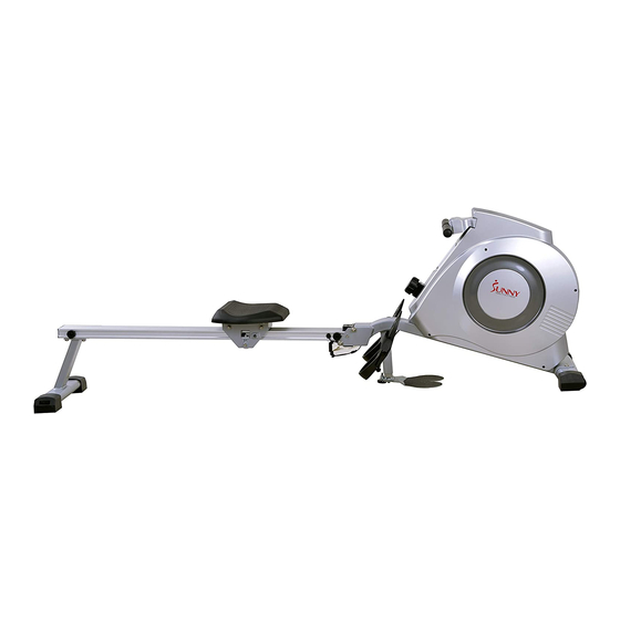
- Page 1 DUAL FUNCTION ROWING MACHINE SF-RW5612 USER MANUAL IMPORTANT: Read all instructions carefully before using this product. Retain owner’s manual future reference. customer service, please contact: support@sunnyhealthfitness.com...
-
Page 2: Important Safety Information
IMPORTANT SAFETY INFORMATION We thank you for choosing our product. To ensure your safety and health, please use this equipment correctly. It is important to read this entire manual before assembling and using the equipment. Safe and effective use can only be assured if the equipment is assembled, maintained, and used properly. -
Page 3: Exploded Drawing
EXPLODED DRAWING... -
Page 4: Parts List
PARTS LIST Description Description Pull pin Φ8*95*100 Left chain cover Screw ST4.2*19*Φ8 Washer d10*Φ20*2 Screw ST4.2*16*Φ8 Bolt Φ12*104.5*M10*15*S19 Screw ST4.2*25*Φ10.5 Bolt M6*10*S10 Bolt M6*12*S10 End cap with wheel R PT80*40*71.5*90*65 R Washer d6*Φ16*1.5 Bolt M8*50*20*S6 Washer d8*Φ16*1.5 Fixed plate t1.5*56*76 Bearing 6001-2RS Front stabilizer Bearing seat Φ72*11... - Page 5 Limit axle Φ12*80*M6 Adjustable end cap PT80*40*71.5*90*65 U shape baffle t2.0*183*38 Rear stabilizer Bolt M8*16*S6 Screw M8*20*S6 Round end cap Φ28*15 Spring washer d8 Foam grip Φ26*3*188 Saddle Handlebar Φ28*1.5*400 Right seat supporting board Spacer d8*Φ15*4 Sensor wire Length 600 Magnet Φ15*7 Pull pin Φ4.5*26 Washer d5*Φ10*1.0...
-
Page 6: Hardware Package
HARDWARE PACKAGE... -
Page 7: Assembly Instructions
ASSEMBLY INSTRUCTIONS STEP 1: Attach the Front Stabilizer (No. 53) to the Main Frame (No. 42) using 2 Bolts (No. 51) and 2 Washers (No. 52). Tighten and secure with Allen Wrench (No. 118). - Page 8 ASSEMBLY INSTRUCTIONS STEP 2: Fix the 2 Bolts (No. 44) into the bottom hole of Main Frame (No. 42) with Spanner (No.119). Insert the 2 Bolts (No. 44) through the Pedals (No. 43) into the upper hole of the Main Frame (No. 42) and tighten with Spanner (No.119).
- Page 9 ASSEMBLY INSTRUCTIONS STEP 3: Insert the Saddle (No. 95) into the Sliding Rail (No. 103). Insert the Limit Axle (No. 91) into the hole on the back of the Sliding Rail (No. 103). Attach the 2 Limit Mats (No. 86) onto the Limit Axle (No. 91) using 2 Screws (No. 84) and 2 Washers (No.
- Page 10 ASSEMBLY INSTRUCTIONS STEP 4: Attach the Sliding Rail (No. 103) onto the Rear Stabilizer (No. 108) using 4 Screws (No. 109), 4 Spring Washers (No. 94), and 4 Washers (No. 52). Tighten and secure with Allen Wrench (No. 118).
- Page 11 ASSEMBLY INSTRUCTIONS STEP 5: Attach the Sliding Rail (No. 103) to the bolt of the Main Frame (No. 42), then insert the Pull Pin (No. 46). Connect Trunk Wire 1 (No. 41) with the Sensor Wire (No. 113). Your rowing machine is now assembled.
- Page 12 This rowing machine has dual functions. You can row while seated or you can stand on the Foot Plates (No. 72 & 78) and pull the handlebar up vertically, giving you more options to exercise your arms and upper body. To use for standing exercises, turn Right Foot Plate (No.
- Page 13 To use the machine as rowing machine, turn Right Foot Plate (No. 72) counterclockwise and the Left Foot Plate (No. 78) clockwise, back to center. Note: when use as rowing machine, please turn back Pedals (No. 43) to position shown above.
-
Page 14: Adjustment Guide
ADJUSTMENT GUIDE PEDAL ADJUSTMENT The pedal strap is adjustable and can be personalized to fit the user’s foot size. To adjust the pedal strap, remove the Velcro end of the strap from the mesh side by pulling it upward then to the left. Once removed, you may increase the opening of the pedal strap by pulling the mesh end up and to the right. -
Page 15: Adjusting The Balance
ADJUSTMENT GUIDE ADJUSTING THE BALANCE If the machine is not level, turn the dials on the rear stabilizer to adjust the End Caps (No. 107) ADJUSTING THE RESISTANCE Rotate the Tension Control Knob (No. 36) clockwise to increase the level of resistance. Rotate the tension control counter-clockwise to decrease the level of resistance. - Page 16 Replacement of Battery If there is a problem with the computer display, replace the batteries. Take the Computer (No. 35) out from Main Frame (No. 42). Disconnect the Sensor Wire 1 (No. 41) and wire of Computer (No. 35). Open the back cover of Computer (No. 35) and replace the batteries. Connect Sensor Wire 1 (No.
-
Page 17: Function Key
EXERCISE METER Our computerized display console on the Dual Function Rowing Machine allows the user to tailor a personalized workout by monitoring their progress. During a workout, the display console will alternately and repeatedly display your Time, Count, Calories Burned, Total Count, and Scan (all of the above).
Need help?
Do you have a question about the SF-RW5612 and is the answer not in the manual?
Questions and answers