Table of Contents
Advertisement
Quick Links
Advertisement
Table of Contents

Related Manuals for IEI Technology KINO-DH610


Summary of Contents for IEI Technology KINO-DH610
-
Page 1: User Manual
KINO-DH610 KINO-DH610 CPU Card IEI Technology Corp. MODEL: KINO-DH610 Mini-ITX SBC Supports LGA1155 for Intel® Core™ i3/ Pentium®/ Celeron® CPU, DDR3, VGA/DVI-D/HDMI, Dual PCIe GbE, Ten USB 2.0, Four SATA 3Gb/s, HD Audio and RoHS User Manual Page I Rev. 1.00 - 30 December, 2011... - Page 2 KINO-DH610 Revision Date Version Changes 30 December, 2011 1.00 Initial release Page II...
- Page 3 KINO-DH610 Copyright COPYRIGHT NOTICE The information in this document is subject to change without prior notice in order to improve reliability, design and function and does not represent a commitment on the part of the manufacturer. In no event will the manufacturer be liable for direct, indirect, special, incidental, or consequential damages arising out of the use or inability to use the product or documentation, even if advised of the possibility of such damages.
-
Page 4: Table Of Contents
PTIONAL TEMS 3 CONNECTORS ......................14 3.1 P ..............15 ERIPHERAL NTERFACE ONNECTORS 3.1.1 KINO-DH610 Layout..................15 3.1.2 Peripheral Interface Connectors ..............16 3.1.3 External Interface Panel Connectors............... 17 3.2 I ..............17 NTERNAL ERIPHERAL ONNECTORS 3.2.1 Battery Connector.................... 17 3.2.2 BIOS Update Connector .................. - Page 5 KINO-DH610 3.2.13 Power Connector ................... 28 3.2.14 SATA Drive Connectors ................. 28 3.2.15 SATA Power Connectors ................29 3.2.16 Serial Port Connector (RS-232/422/485) ............30 3.2.17 TPM Connector....................31 3.2.18 USB Connectors..................... 32 3.3 E ......... 33 XTERNAL ERIPHERAL NTERFACE...
- Page 6 KINO-DH610 5.1 I ......................61 NTRODUCTION 5.1.1 Starting Setup....................61 5.1.2 Using Setup ...................... 61 5.1.3 Getting Help..................... 62 5.1.4 Unable to Reboot after Configuration Changes ..........62 5.1.5 BIOS Menu Bar....................62 5.2 M ........................63 5.3 A ....................... 64 DVANCED 5.3.1 ACPI Configuration ..................
- Page 7 KINO-DH610 6.5 LAN D .................. 103 RIVER NSTALLATION 6.6 A ................105 UDIO RIVER NSTALLATION A BIOS MENU OPTIONS ................... 108 B ONE KEY RECOVERY ....................111 B.1 O ..............112 ECOVERY NTRODUCTION B.1.1 System Requirement..................113 B.1.2 Supported Operating System ................114 B.2 S .................115...
- Page 8 Figure 3-16: SATA Power Connector Locations ...............29 Figure 3-17: RS-232/422/485 Serial Port Connector Location(RS-232+RS422/485)..30 Figure 3-18: TPM Connector Location..................31 Figure 3-19: USB Connector Locations..................32 Figure 3-20: KINO-DH610 External Peripheral Interface Connector........33 Figure 3-21: Audio Connector .....................34 Figure 3-22: LAN Connector......................35 Figure 3-23: Power Connector ....................36 Figure 3-24: RS-232 Serial Port Connector................37...
- Page 9 KINO-DH610 Figure 4-3: Insert the Socket LGA1155 CPU................44 Figure 4-4: Close the Socket LGA1155 ..................45 Figure 4-5: Cooling Kits (CF-1156A-RS, CF-1156B-RS, CF-1156C-RS, CF-1156D-RS)..45 Figure 4-6: Cooling Kit Support Bracket ..................46 Figure 4-7: DIMM Installation.......................47 Figure 4-8: Jumper Locations .....................48 Figure 4-9: AT/ATX Mode Select Jumper Location ..............49 Figure 4-10: Clear CMOS Jumper Location ................50...
- Page 10 KINO-DH610 Figure 6-20: Audio Driver Installation Complete ..............107 Figure B-1: IEI One Key Recovery Tool Menu ................ 112 Figure B-2: Launching the Recovery Tool ................117 Figure B-3: Recovery Tool Setup Menu .................. 117 Figure B-4: Command Mode..................... 117 Figure B-5: Partition Creation Commands................
- Page 11 KINO-DH610 List of Tables Table 1-1: Technical Specifications....................8 Table 3-1: Peripheral Interface Connectors ................16 Table 3-2: Rear Panel Connectors ....................17 Table 3-3: Battery Connector Pinouts ..................18 Table 3-4: BIOS Update Connector Pinouts ................19 Table 3-5: Debug Port Connector Pinouts .................21 Table 3-6: Digital I/O Connector Pinouts..................22...
- Page 12 KINO-DH610 List of BIOS Menus BIOS Menu 1: Main ........................63 BIOS Menu 2: Advanced ......................65 BIOS Menu 3: ACPI Configuration ....................65 BIOS Menu 4: TPM Configuration ....................66 BIOS Menu 5: CPU Configuration ....................67 BIOS Menu 6: CPU Configuration ....................68 BIOS Menu 7: IDE Configuration....................69 BIOS Menu 9: USB Configuration ....................71...
-
Page 13: Introduction
KINO-DH610 Chapter Introduction Page 1... -
Page 14: Introduction
SATA 3Gb/s drives and provides 5 V SATA power. The KINO-DH610 includes a VGA, DVI-D and HDMI port. Expansion and I/O include one PCI slot, one PCIe x1 slot, four USB 2.0 ports on the rear panel and six USB 2.0 ports by pin header. -
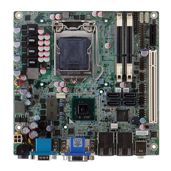
Page 15: Figure 1-2: Connectors
KINO-DH610 Figure 1-2: Connectors Page 3... -
Page 16: Dimensions
KINO-DH610 1.3 Dimensions The dimensions of the board are listed below: Length: 170 mm Width: 170 mm Figure 1-3: KINO-DH610 Dimensions (mm) Page 4... -
Page 17: Data Flow
KINO-DH610 1.4 Data Flow Figure 1-4 shows the data flow between the system chipset, the CPU and other components installed on the motherboard. Figure 1-4: Data Flow Diagram Page 5... -
Page 18: Technical Specifications
KINO-DH610 1.5 Technical Specifications KINO-DH610 technical specifications are listed in table below. Specification KINO-DH610 Form Factor Mini-ITX Socket LGA1155 Socket 1155 Intel® Core™ i3/ Pentium®/ Celeron® dual core CPU Supported processor Intel® H61 System Chipset Two 204-pin 1066/1333 MHz dual-channel DDR3 SO-DIMM Memory supported (system max. - Page 19 KINO-DH610 Specification KINO-DH610 Display Ports One VGA integrated in Intel® H61 One DVI-D integrated in Intel® H61 One HDMI integrated in Intel® H61 Ethernet Two RJ-45 GbE ports Keyboard/Mouse One internal keyboard and mouse connector via 6-pin wafer One 20-pin header...
-
Page 20: Table 1-1: Technical Specifications
KINO-DH610 Specification KINO-DH610 1100 g / 700 g Weight GW/NW Table 1-1: Technical Specifications Page 8... -
Page 21: Unpacking
KINO-DH610 Chapter Unpacking Page 9... -
Page 22: Anti-Static Precautions
Only handle the edges of the PCB: Don't touch the surface of the motherboard. Hold the motherboard by the edges when handling. 2.2 Unpacking Precautions When the KINO-DH610 is unpacked, please do the following: Follow the antistatic guidelines above. -
Page 23: Packing List
If any of the components listed in the checklist below are missing, do not proceed with the installation. Contact the IEI reseller or vendor the KINO-DH610 was purchased from or contact an IEI sales representative directly by sending an email to sales@iei.com.tw. -
Page 24: Optional Items
KINO-DH610 2.4 Optional Items The following are optional components which may be separately purchased: Item and Part Number Image Dual-port USB cable with bracket (P/N: 19800-003100-100-RS) High-performance LGA1155/LGA1156 cooler kit, 1U chassis compatible, 73W (P/N: CF-1156A-RS) High-performance LGA1155/LGA1156 cooler kit, 95W... - Page 25 KINO-DH610 SATA to CF converter board (P/N: SACF-KIT01-R10) Keyboard/Mouse Y cable (P/N: 32000-023800-RS) Page 13...
-
Page 26: Connectors
KINO-DH610 Chapter Connectors Page 14... -
Page 27: Peripheral Interface Connectors
KINO-DH610 3.1 Peripheral Interface Connectors This chapter details all the jumpers and connectors. 3.1.1 KINO-DH610 Layout The figures below show all the connectors and jumpers. Figure 3-1: Connector and Jumper Locations Page 15... -
Page 28: Peripheral Interface Connectors
KINO-DH610 3.1.2 Peripheral Interface Connectors The table below lists all the connectors on the board. Connector Type Label Battery connector 2-pin wafer BAT2 BIOS update connector 6-pin header SPI1 DDR3 SO-DIMM slots DDR3 SO-DIMM slot CHA_DIMM1,CHB_DIMM1 Debug port connector 18-pin header... -
Page 29: External Interface Panel Connectors
VGA and DVI connector 15-pin female, DVI_CRT1 24-pin female Table 3-2: Rear Panel Connectors 3.2 Internal Peripheral Connectors The section describes all of the connectors on the KINO-DH610. 3.2.1 Battery Connector CN Label: BAT2 CN Type: 2-pin wafer CN Location:... -
Page 30: Bios Update Connector
KINO-DH610 Figure 3-2: Battery Connector Location PIN NO. DESCRIPTION PIN NO. DESCRIPTION VBATT Table 3-3: Battery Connector Pinouts 3.2.2 BIOS Update Connector CN Label: SPI1 CN Type: 6-pin wafer (1x6) See Figure 3-3 CN Location: CN Pinouts: See Table 3-4 The connector is for BIOS updating. -
Page 31: Ddr3 So-Dimm Slots
KINO-DH610 Figure 3-3: BIOS Update Connector Location PIN NO. DESCRIPTION PIN NO. DESCRIPTION +SPI_VCC SPI_CS0#_CN SPI_SO0_CN SPI_CLK0_CN SPI_SI0_CN Table 3-4: BIOS Update Connector Pinouts 3.2.3 DDR3 SO-DIMM Slots CN Label: CHA_DIMM1, CHB_DIMM1 CN Type: DDR3 SO-DIMM slot CN Location: See Figure 3-4 The DDR3 DIMM slots are for DDR3 SO-DIMM memory modules. -
Page 32: Debug Port Connector
KINO-DH610 Figure 3-4: DDR3 SO-DIMM Slot Locations 3.2.4 Debug Port Connector CN Label: CN Type: 18-pin header (2x9) CN Location: See Figure 3-5 CN Pinouts: See Table 3-5 The debug port connector is for system debug. Figure 3-5: Debug Port Connector Location... -
Page 33: Digital I/O Connector
KINO-DH610 PIN NO. DESCRIPTION PIN NO. DESCRIPTION EC_EPP_STB# EC_EPP_AFD# EC_EPP_PD0 EC_EPP_ERR# EC_EPP_PD1 EC_EPP_INIT# EC_EPP_PD2 EC_EPP_SLIN# EC_EPP_PD3 EC_EPP_PD4 EC_EPP_ACK# EC_EPP_PD5 EC_EPP_BUSY EC_EPP_PD6 EC_EPP_PE EC_EPP_PD7 EC_EPP_SLCT Table 3-5: Debug Port Connector Pinouts 3.2.5 Digital I/O Connector CN Label: DIO2 CN Type: 10-pin header (2x5) -
Page 34: Ec Update Connector
KINO-DH610 PIN NO. DESCRIPTION PIN NO. DESCRIPTION D_IN0 D_OUT0 D_IN1 D_OUT1 D_IN2 D_OUT2 D_IN3 D_OUT3 Table 3-6: Digital I/O Connector Pinouts 3.2.6 EC Update Connector CN Label: JSPI2 CN Type: 6-pin connector CN Location: See Figure 3-7 CN Pinouts: See Table 3-7 The connector is for EC updating. -
Page 35: Fan Connector (Cpu)
KINO-DH610 PIN NO. DESCRIPTION +V3.3A_EC_CONN FSCE# FMISO FSCK FMOSI SGND Table 3-7: EC Update Connector Pinouts 3.2.7 Fan Connector (CPU) CN Label: CPU_FAN1 CN Type: 4-pin wafer CN Location: See Figure 3-8 CN Pinouts: See Table 3-8 The fan connector attaches to a CPU cooling fan. -
Page 36: Fan Connector (Pch)
KINO-DH610 3.2.8 Fan Connector (PCH) CN Label: PCH_FAN1 3-pin wafer CN Type: CN Location: See Figure 3-9 CN Pinouts: See Table 3-9 The fan connector connects to a PCH cooling fan. Figure 3-9: PCH Fan Connector Location PIN NO. DESCRIPTION... -
Page 37: Keyboard/Mouse Connector
KINO-DH610 The front panel connector connects to the indicator LEDs and buttons on the computer’s front panel. Figure 3-10: Front Panel Connector Location PIN NO. DESCRIPTION PIN NO. DESCRIPTION IDELED PWRLED IDELED# EXTRST# PWRBTN_SW# Table 3-10: Front Panel Connector Pinouts 3.2.10 Keyboard/Mouse Connector... -
Page 38: Pci Slot
KINO-DH610 Figure 3-11: Keyboard/Mouse Connector Location PIN NO. DESCRIPTION MSDATA MSCLK KBDATA KBCLK Table 3-11: Keyboard/Mouse Connector Pinouts 3.2.11 PCI Slot CN Label: PCI1 CN Type: PCI Slot CN Location: See Figure 3-12 The PCI slot enables a PCI expansion module to be connected to the board. -
Page 39: Pcie X1 Slot
KINO-DH610 Figure 3-12: PCI Slot Location 3.2.12 PCIe x1 Slot CN Label: PCIE1 CN Type: PCIe x1 slot CN Location: See Figure 3-13 The PCIe x1 slot is for PCIe x1 expansion cards. Figure 3-13: PCIe x1 Slot Location Page 27... -
Page 40: Power Connector
KINO-DH610 3.2.13 Power Connector CN Label: DC_IN2 CN Type: 4-pin header CN Location: See Figure 3-16 CN Pinouts: See Table 3-13 The power connector provides 12 V power to the motherboard. Figure 3-14: Power Connector Location PIN NO. DESCRIPTION WIDE_VIN... -
Page 41: Sata Power Connectors
KINO-DH610 The four SATA 3Gb/s drive connectors are each connected to a SATA 3Gb/s drive. The SATA 3Gb/s drives transfer data at speeds as high as 3Gb/s. Figure 3-15: SATA Drive Connector Locations 3.2.15 SATA Power Connectors CN Label: SATA_PWR1, SATA_PWR2... -
Page 42: Serial Port Connector (Rs-232/422/485)
KINO-DH610 PIN NO. DESCRIPTION Table 3-13: SATA Power Connector Pinouts 3.2.16 Serial Port Connector (RS-232/422/485) CN Label: COM3 14-pin header CN Type: CN Location: See Figure 3-17 CN Pinouts: See Table 3-14 This connector provides one RS-232 and one RS-422/485 communications. -
Page 43: Tpm Connector
KINO-DH610 PIN NO. DESCRIPTION TXD485+_B_R TXD485_B_R RXD485+_B_R RXD485_B_R Table 3-14: RS-232/422/485 Serial Port Connector Pinouts(RS-232+RS422/485) 3.2.17 TPM Connector CN Label: TPM1 20-pin connector CN Type: CN Location: See Figure 3-18 CN Pinouts: See Table 3-15 The Trusted Platform Module (TPM) connector secures the system on bootup. -
Page 44: Usb Connectors
KINO-DH610 PIN NO. DESCRIPTION PIN NO. DESCRIPTION TPMPCLK LPC_FRAME# BUF_PCIRST# LPC_AD3 LPC_AD2 +3.3V LPC_AD1 LPC_AD0 SMBCLK_RESUME SMBDATA_RESUME +3V_DUAL SERIRQ +3.3V LPCPD_N LDRQ0# Table 3-15: TPM Connector Pinouts 3.2.18 USB Connectors CN Label: USB2, USB3, USB4 CN Type: 8-pin header (2x4) -
Page 45: External Peripheral Interface Connector Panel
USB20_C_P9 USB20_C_P8 USB20_C_N9 Table 3-16: USB Connector Pinouts 3.3 External Peripheral Interface Connector Panel Figure 3-20 shows the KINO-DH610 external peripheral interface connector (EPIC) panel. The EPIC panel consists of the following: 2 x Audio jacks 1 x DVI connector ... -
Page 46: Audio Connector
KINO-DH610 3.3.1 Audio Connector CN Label: AUDIO_JACK2 CN Type: Audio jack CN Location: See Figure 3-20 The audio jacks connect to external audio devices. Line Out port (Lime): Connects to a headphone or a speaker. With multi-channel configurations, this port can also connect to front speakers. -
Page 47: Hdmi Connector
KINO-DH610 Figure 3-22: LAN Connector The USB connector can be connected to a USB device. PIN NO. DESCRIPTION PIN NO. DESCRIPTION +V3.3A_LAN1 LAN1_MDIP0 LAN1_MDIN0 LAN1_MDIP1 LAN1_MDIN1 LAN1_MDIP2 LAN1_MDN2 LAN1_MDIP3 LAN1_MDIN3 LAN1_LINK100 LAN1_LINK1000 LAN1_ACT-1 +V3.3A_LAN1 +USB_PWR1 USB20_C_N0 USB20_C_P0 +USB_PWR1 USB20_C_N1 USB20_C_P1 Table 3-17: LAN and USB Connector Pinouts 3.3.3 HDMI Connector... -
Page 48: Power Connector
KINO-DH610 PIN NO. DESCRIPTION PIN NO. DESCRIPTION HDMI_TMDS_C_DATA2 HDMI_TMDS_C_DATA2# HDMI_TMDS_C_DATA1 HDMI_TMDS_C_DATA1# HDMI_TMDS_C_DATA0 HDMI_TMDS_C_DATA0# HDMI_TMDS_C_CLK HDMI_TMDS_C_CLK# HDMI_DDC_SCLK HDMI_DDC_SDATA +5V_HDMI HDMI_HPD Table 3-18: HDMI Connector Pinouts 3.3.4 Power Connector CN Label: DC_CN1 CN Type: 4-pin Mini-DIN CN Location: See Figure 3-20 CN Pinouts: See Figure 3-23 and Table 3-19 The connector supports 12 V power adapter. -
Page 49: Serial Port
KINO-DH610 PIN NO. DESCRIPTION Table 3-19: Power Connector Pinouts 3.3.5 RS-232 Serial Port CN Label: COM1 CN Type: DB-9 Male CN Location: See Figure 3-20 CN Pinouts: See Figure 3-24 and Table 3-20 The serial port connects to a RS-232 serial communications device. -
Page 50: Vga And Dvi Connector
KINO-DH610 3.3.6 VGA and DVI Connector CN Label: DVI_CRT1 15-pin female (VGA) , 24-pin female (DVI) CN Type: CN Location: See Figure 3-20 CN Pinouts: See Figure 3-25 and Table 3-21 The VGA port connects to a monitor that accepts a standard VGA input. -
Page 51: Installation
KINO-DH610 Chapter Installation Page 39... -
Page 52: Anti-Static Precautions
Electrostatic discharge (ESD) can cause serious damage to electronic components, including the KINO-DH610. Dry climates are especially susceptible to ESD. It is therefore critical that whenever the KINO-DH610 or any other electrical component is handled, the following anti-static precautions are strictly adhered to. -
Page 53: Installation Considerations
KINO-DH610 is installed. All installation notices pertaining to the installation of the KINO-DH610 should be strictly adhered to. Failing to adhere to these precautions may lead to severe damage of the KINO-DH610 and injury to the person installing the motherboard. WARNING:... -
Page 54: Basic Installation
Running a CPU without a cooling kit may also result in injury to the user. The CPU, CPU cooling kit and DIMM are the most critical components of the KINO-DH610. If one of these component is not installed the KINO-DH610 cannot run. 4.3.1 Socket LGA1155 CPU Installation WARNING: CPUs are expensive and sensitive components. -
Page 55: Figure 4-1: Disengage The Cpu Socket Load Lever
KINO-DH610 To install the CPU, follow the steps below. Step 1: Disengage the load lever by pressing the lever down and slightly outwards to clear the retention tab. Fully open the lever. See Figure 4-1. Figure 4-1: Disengage the CPU Socket Load Lever Step 2: Open the socket and remove the protective cover. -
Page 56: Figure 4-3: Insert The Socket Lga1155 Cpu
KINO-DH610 Step 4: Orientate the CPU properly. The contact array should be facing the CPU socket. Step 5: Correctly position the CPU. Match the Pin 1 mark with the CPU edge on the CPU socket. Step 6: Align the CPU pins. Locate pin 1 and the two orientation notches on the CPU. -
Page 57: Cooling Kit Installation
KINO-DH610 Figure 4-4: Close the Socket LGA1155 Step 9: Connect the 12 V power to the board. Connect the 12 V power from the power supply to the board. 4.3.2 Cooling Kit Installation WARNING: DO NOT attempt to install a push-pin cooling fan. -
Page 58: Figure 4-6: Cooling Kit Support Bracket
KINO-DH610 WARNING: Do not wipe off (accidentally or otherwise) the pre-sprayed layer of thermal paste on the bottom of the heat sink. The thermal paste between the CPU and the heat sink is important for optimum heat dissipation. To install the cooling kit, follow the instructions below. -
Page 59: Dimm Installation
Secure the cooling kit by fastening the four retention screw of the cooling kit. Step 5: Connect the fan cable. Connect the cooling kit fan cable to the fan connector on the KINO-DH610. Carefully route the cable and avoid heat generating chips and fan blades. 4.3.3 DIMM Installation To install a DIMM, please follow the steps below and refer to Figure 4-7. -
Page 60: Jumper Settings
OPEN a jumper means removing the Figure 4-8: Jumper Locations plastic clip from a jumper. Before the KINO-DH610 is installed in the system, the jumpers must be set in accordance with the desired configuration. The jumpers on the KINO-DH610 are listed in Table 4-1. Description... -
Page 61: Clear Cmos Jumper
Jumper Location: See Figure 4-10 If the KINO-DH610 fails to boot due to improper BIOS settings, the clear CMOS jumper clears the CMOS data and resets the system BIOS information. To do this, use the jumper cap to close pins 2 and 3 for a few seconds then reinstall the jumper clip back to pins 1 and 2. -
Page 62: Internal Peripheral Device Connections
KINO-DH610 If the “CMOS Settings Wrong” message is displayed during the boot up process, the fault may be corrected by pressing the F1 to enter the CMOS Setup menu. Do one of the following: Enter the correct CMOS setting ... -
Page 63: Sata Drive Connection
KINO-DH610 4.5.1 SATA Drive Connection The KINO-DH610 is shipped with two SATA drive cables and one SATA drive power cable. To connect the SATA drives to the connectors, please follow the steps below. Step 1: Locate the connectors. The locations of the SATA drive connectors are shown in Chapter 3. -
Page 64: External Peripheral Interface Connection
Serial port devices USB devices VGA monitor To install these devices, connect the corresponding cable connector from the actual device to the corresponding KINO-DH610 external peripheral interface connector making sure the pins are properly aligned. Page 52... -
Page 65: Audio Connection
KINO-DH610 4.6.1 Audio Connection The audio jacks on the external audio connector enable the KINO-DH610 to be connected to a stereo sound setup. To install the audio devices, follow the steps below. Step 1: Identify the audio plugs. The plugs on your home theater system or speakers may not match the colors on the rear panel. -
Page 66: Hdmi Display Device Connection
4.6.3 HDMI Display Device Connection The KINO-DH610 has one female HDMI connector on the external peripheral interface panel. The HDMI connectors are connected to digital display devices. To connect a digital display device to the KINO-DH610, please follow the instructions below. -
Page 67: Lan Connection
Locate the RJ-45 connectors. The location of the LAN connectors is shown in Chapter 3. Step 2: Align the connectors. Align the RJ-45 connector on the LAN cable with one of the RJ-45 connectors on the KINO-DH610. See Figure 4-15. Page 55... -
Page 68: Serial Device Connection
RJ-45 connector into the on-board RJ-45 connector. 4.6.5 Serial Device Connection The KINO-DH610 has a single female DB-9 connector on the external peripheral interface panel for a serial device. Follow the steps below to connect a serial device to the KINO-DH610. -
Page 69: Usb Connection
KINO-DH610 Figure 4-16: Serial Device Connector Step 3: Secure the connector. Secure the serial device connector to the external interface by tightening the two retention screws on either side of the connector 4.6.6 USB Connection The external USB Series "A" receptacle connectors provide easier and quicker access to external USB devices. -
Page 70: Vga Monitor Connection
Figure 4-17: USB Connector 4.6.7 VGA Monitor Connection The KINO-DH610 has a single female DB-15 connector on the external peripheral interface panel. The DB-15 connector is connected to a CRT or VGA monitor. To connect a monitor to the KINO-DH610, please follow the instructions below. -
Page 71: Figure 4-18: Vga Connector
KINO-DH610 Figure 4-18: VGA Connector Step 4: Secure the connector. Secure the DB-15 VGA connector from the VGA monitor to the external interface by tightening the two retention screws on either side of the connector. Page 59... -
Page 72: Bios Screens
KINO-DH610 Chapter BIOS Screens Page 60... -
Page 73: Introduction
KINO-DH610 5.1 Introduction The BIOS is programmed onto the BIOS chip. The BIOS setup program allows changes to certain system settings. This chapter outlines the options that can be changed. 5.1.1 Starting Setup The AMI BIOS is activated when the computer is turned on. The setup program can be activated in one of two ways. -
Page 74: Getting Help
KINO-DH610 Function F4 key Save changes and Exit BIOS Esc key Main Menu – Quit and not save changes into CMOS Status Page Setup Menu and Option Page Setup Menu -- Exit current page and return to Main Menu Table 5-1: BIOS Navigation Keys 5.1.3 Getting Help... -
Page 75: Main
KINO-DH610 5.2 Main The Main BIOS menu (BIOS Menu 1) appears when the BIOS Setup program is entered. The Main menu gives an overview of the basic system information. Aptio Setup Utility – Copyright (C) 2011 American Megatrends, Inc. Main... -
Page 76: Advanced
KINO-DH610 iWDD Version The iWDD Version displays the current iWDD version. The fields in iWDD Version cannot be changed. Memory Information The Memory Information lists a brief summary of the on-board memory. The fields in Memory Information cannot be changed. -
Page 77: Acpi Configuration
KINO-DH610 Aptio Setup Utility – Copyright (C) 2011 American Megatrends, Inc. Main Advanced Chipset Boot Security Save & Exit > ACPI Settings System ACPI Parameters > Trusted Computing > CPU Configuration > SATA Configuration > USB Configuration ---------------------- : Select Screen >... -
Page 78: Trusted Computing
KINO-DH610 ACPI Sleep State [S1 (CPU Stop Clock)] Use the ACPI Sleep State option to specify the sleep state the system enters when it is not being used. Suspend Disabled The system enters S1 (POS) sleep state. The... -
Page 79: Cpu Configuration
KINO-DH610 TPM Support [Disable] Use the TPM Support option to configure support for the TPM. TPM support is disabled. Disable EFAULT Enable TPM support is enabled. 5.3.3 CPU Configuration Use the CPU Configuration menu (BIOS Menu 5) to enter the CPU Information submenu or enable Intel Virtualization Technology. -
Page 80: Cpu Information
KINO-DH610 5.3.3.1 CPU Information Use the CPU Information submenu (BIOS Menu 6) to view detailed CPU specifications and configure the CPU. Aptio Setup Utility – Copyright (C) 2011 American Megatrends, Inc. Advanced CPU Configuration Intel(R) Core (TM) i3-2100T CPU @ 2.50GHz... -
Page 81: Sata Configuration
KINO-DH610 5.3.4 SATA Configuration Use the SATA Configuration menu (BIOS Menu 7) to change and/or set the configuration of the SATA devices installed in the system. Aptio Setup Utility – Copyright (C) 2011 American Megatrends, Inc. Advanced SATA Configuration (1) IDE Mode. (2) AHCI Mode. - Page 82 KINO-DH610 Enhanced Configures the Serial-ATA controller to be in enhanced mode. In this mode, IDE channels and SATA channels are separated. Some legacy OS do not support this mode. Configures the Serial-ATA controller to be in compatible Compatible DEFAULT mode.
-
Page 83: Usb Configuration
KINO-DH610 5.3.5 USB Configuration Use the USB Configuration menu (BIOS Menu 8) to read USB configuration information and configure the USB settings. Aptio Setup Utility – Copyright (C) 2011 American Megatrends, Inc. Advanced USB Configuration Enables BIOS USB support. This item does... -
Page 84: Super Io Configuration
KINO-DH610 keyboard can control the system even when there is no USB driver loaded onto the system. Disabled Legacy USB support disabled Enabled Legacy USB support enabled EFAULT 5.3.6 Super IO Configuration Use the Super IO Configuration menu (BIOS Menu 9) to set or change the configurations for the FDD controllers, parallel ports and serial ports. -
Page 85: Serial Port N Configuration
KINO-DH610 5.3.6.1 Serial Port n Configuration Use the Serial Port n Configuration menu (BIOS Menu 14) to configure the serial port n. Aptio Setup Utility – Copyright (C) 2011 American Megatrends, Inc. Advanced Serial Port n Configuration Enable or Disable Serial... - Page 86 KINO-DH610 IO=3F8h; Serial Port I/O port address is 3F8h and the interrupt IRQ=3, 4 address is IRQ3,4 Serial Port I/O port address is 2F8h and the interrupt IO=2F8h; address is IRQ3,4 IRQ=3, 4 IO=2C0h; Serial Port I/O port address is 2C0h and the interrupt...
- Page 87 KINO-DH610 IO=2C8h; Serial Port I/O port address is 2C8h and the interrupt IRQ=10, 11 address is IRQ10, 11 5.3.6.1.3 Serial Port 3 Configuration Serial Port [Enabled] Use the Serial Port option to enable or disable the serial port.
-
Page 88: H/W Monitor
KINO-DH610 5.3.7 H/W Monitor The H/W Monitor menu (BIOS Menu 11) shows the operating temperature, fan speeds and system voltages. Aptio Setup Utility – Copyright (C) 2011 American Megatrends, Inc. Advanced PC Health Status CPU Temperature :+50 C SYS Temperature... -
Page 89: Cpu Fan Configuration
KINO-DH610 VDDR VSB3V VBAT 5VSB 5.3.7.1 CPU Fan Configuration Use the CPU Fan Configuration submenu (BIOS Menu 12) to configure CPU fan temperature and speed settings. Aptio Setup Utility – Copyright (C) 2011 American Megatrends, Inc. Advanced PC Health Status... -
Page 90: Sys Fan 1 Configuration
KINO-DH610 Manual The fan spins at the speed set in Manual by PWM settings Target Temp. Sensor [CPU Temperature] Use the Target Temp. Sensor option to set the target CPU temperature. Sets the target temperature sensor to the CPU EFAULT temperature. - Page 91 KINO-DH610 Aptio Setup Utility – Copyright (C) 2011 American Megatrends, Inc. Advanced PC Health Status SYS Smart Fan control [Auto by PWM] Target Temp Sensor [CPU Temperature] Temperature Bound 1 Temperature Bound 2 Temperature Bound 3 Temperature Bound 4 Segment 1 Speed (PWM) --------------------- : Select Screen...
-
Page 92: Serial Port Console Redirection
KINO-DH610 System Sets the target temperature sensor to the System Temperature1 Temperature1 setting. Sets the target temperature sensor to the System System Temperature2 setting. Temperature2 Temperature Bound n Use the + or – key to change the fan Temperature Bound n value. Enter a decimal number between 0 and 127. -
Page 93: Iei Feature
KINO-DH610 Console Redirection Use Console Redirection option to enable or disable the console redirection function. Disabled the console redirection function Disabled Enabled Enabled the console redirection function 5.3.9 IEI Feature Use the IEI Feature menu (BIOS Menu 15) to configure One Key Recovery function. -
Page 94: Chipset
KINO-DH610 Enabled Auto recovery function enabled 5.4 Chipset Use the Chipset menu (BIOS Menu 16) to access the Northbridge and Southbridge configuration menus WARNING! Setting the wrong values for the Chipset BIOS selections in the Chipset BIOS menu may cause the system to malfunction. -
Page 95: Northbridge Configuration
KINO-DH610 5.4.1 Northbridge Configuration Use the Northbridge Chipset Configuration menu (BIOS Menu 17) to configure the Northbridge chipset. Aptio Setup Utility – Copyright (C) 2011 American Megatrends, Inc. Chipset Memory Information Select which graphics controller to use as the Total Memory 1024 MB (DDR3 1333) primary boot device. - Page 96 KINO-DH610 IGD Memory [64 M] Use the IGD Memory option to specify the amount of system memory that can be used by the Internal graphics device. Disable 32 MB of memory used by internal graphics device 32 M ...
-
Page 97: Southbridge Configuration
KINO-DH610 480 M 480 MB of memory used by internal graphics device 512 MB of memory used by internal graphics 512 M device VT-d [Disabled] Use the VT-d option to enable or disable VT-d support. Disabled Disables VT-d support. - Page 98 KINO-DH610 Aptio Setup Utility – Copyright (C) 2011 American Megatrends, Inc. Chipset Auto Power Button Status [Enabled] Enabled/Disabled All USB controllers Audio Configuration Azalia HD Audio [Enabled] Azalia internal HDMI codec [Enabled] --------------------- : Select Screen : Select Item Enter Select +/-: Change Opt.
-
Page 99: Integrated Graphics
KINO-DH610 5.4.3 Integrated Graphics Use the Integrated Graphics menu (BIOS Menu 19) to configure the video device connected to the system. Aptio Setup Utility – Copyright (C) 2011 American Megatrends, Inc. Advanced Intel IGD SWSCI OpRegion Configuration Select DVMT Mode used by... -
Page 100: Me Subsystem
KINO-DH610 128 MB 256 MB Maximum EFAULT IGD - Boot Type [AUTO] Use the IGD - Boot Type option to select the display device used by the system when it boots. For dual display support, select “Auto.” Configuration options are listed below. -
Page 101: Boot
KINO-DH610 Normal Enables normal mode EFAULT Enables hidden Ctrl+P function Hidden Ctrl + P Enter Enables user to enter MEBx setup MEBx Setup Unconfigure AMT/ME [Disabled] Use the Unconfigure AMT/ME option to perform AMT/ME unconfigure without password operation. - Page 102 KINO-DH610 Bootup NumLock State [On] Use the Bootup NumLock State BIOS option to specify if the number lock setting must be modified during boot up. Allows the Number Lock on the keyboard to be EFAULT enabled automatically when the computer system boots up.
-
Page 103: Security
KINO-DH610 PCIe LAN PXE Boot [Disabled] Use the PCIe LAN PXE Boot option to enable or disable the boot option for the PCIe LAN PXE. Disabled Disables PCIe LAN PXE Boot option EFAULT Enables PCIe LAN PXE Boot option Enabled 5.6 Security... -
Page 104: Save & Exit
KINO-DH610 5.7 Save & Exit Use the Save & Exit menu (BIOS Menu 23) to load default BIOS values, optimal failsafe values and to save configuration changes. Aptio Setup Utility – Copyright (C) 2011 American Megatrends, Inc. Main Advanced Chipset... - Page 105 KINO-DH610 Save as User Defaults Use the Save as User Defaults option to save the changes done so far as user defaults. Restore User Defaults Use the Restore User Defaults option to restore the user defaults to all the setup options.
-
Page 106: Software Drivers
KINO-DH610 Chapter Software Drivers Page 94... -
Page 107: Available Software Drivers
Audio Installation instructions are given below. 6.2 Software Installation All the drivers for the KINO-DH610 are on the CD that came with the system. To install the drivers, please follow the steps below. Step 1: Insert the CD into a CD drive connected to the system. -
Page 108: Figure 6-1: Introduction Screen
KINO-DH610 Figure 6-1: Introduction Screen Step 3: Click KINO-DH610. Step 4: A new screen with a list of available drivers appears (Figure 6-2). Figure 6-2: Available Drivers Page 96... -
Page 109: Chipset Driver Installation
KINO-DH610 Step 5: Install all of the necessary drivers in this menu. 6.3 Chipset Driver Installation To install the chipset driver, please do the following. Step 1: Access the driver list. (See Section 6.2) Step 2: Click “Chipset”. Step 3: Locate the setup file and double click on it. -
Page 110: Figure 6-4: Chipset Driver Welcome Screen
KINO-DH610 Figure 6-4: Chipset Driver Welcome Screen Step 7: The license agreement in Figure 6-5 appears. Step 8: Read the License Agreement. Step 9: Click Yes to continue. Figure 6-5: Chipset Driver License Agreement Step 10: The Read Me file in Figure 6-6 appears. -
Page 111: Figure 6-6: Chipset Driver Read Me File
KINO-DH610 Step 11: Click Next to continue. Figure 6-6: Chipset Driver Read Me File Step 12: Setup Operations are performed as shown in Figure 6-7. Step 13: Once the Setup Operations are complete, click Next to continue. Figure 6-7: Chipset Driver Setup Operations... -
Page 112: Graphics Driver Installation
KINO-DH610 Step 14: The Finish screen in Figure 6-8 appears. Step 15: Select “Yes, I want to restart this computer now” and click Finish.Step 0: Figure 6-8: Chipset Driver Installation Finish Screen 6.4 Graphics Driver Installation To install the Graphics driver, please do the following. -
Page 113: Figure 6-9: Graphics Driver Welcome Screen
KINO-DH610 Figure 6-9: Graphics Driver Welcome Screen Step 6: The License Agreement in Figure 6-10 appears. Step 7: Click Yes to accept the agreement and continue. Figure 6-10: Graphics Driver License Agreement Step 8: Setup Operations are performed as shown in Figure 6-11. -
Page 114: Figure 6-11: Graphics Driver Setup Operations
KINO-DH610 Step 9: Once the Setup Operations are complete, click Next to continue. Figure 6-11: Graphics Driver Setup Operations Step 10: The Finish screen in Figure 6-12 appears. Select “Yes, I want to restart this computer now” and click Finish.Step 0:... -
Page 115: Lan Driver Installation
KINO-DH610 6.5 LAN Driver Installation To install the LAN driver, please do the following. Step 1: Access the driver list. (See Section 6.2) Step 2: Click “LAN” and select the folder which corresponds to the operating system. Step 3: Double click the setup file. -
Page 116: Figure 6-14: Lan Driver Ready To Install Screen
KINO-DH610 Figure 6-14: LAN Driver Ready to Install Screen Step 8: The program begins to install. Step 9: The Setup Status screen in Figure 6-15 appears. Figure 6-15: LAN Driver Setup Status Screen Step 10: When the driver installation is complete, the screen in Figure 6-16 appears. -
Page 117: Audio Driver Installation
KINO-DH610 Figure 6-16: LAN Driver Installation Complete 6.6 Audio Driver Installation To install the audio driver, please do the following. Step 1: Access the driver list. (See Section 6.2) Step 2: Click “Audio” and select the folder which corresponds to the operating system. -
Page 118: Figure 6-17: Audio Driver - Extracting Files
KINO-DH610 Figure 6-17: Audio Driver – Extracting Files Step 5: The Audio Driver Welcome message in Figure 6-18 appears. Step 6: Click Yes to install the audio driver. Figure 6-18: Audio Driver Welcome Screen Step 7: The audio driver installation begins. See Figure 6-19. -
Page 119: Figure 6-20: Audio Driver Installation Complete
KINO-DH610 Figure 6-20: Audio Driver Installation Complete Page 107... -
Page 120: Abios Menu Options
KINO-DH610 Appendix BIOS Menu Options Page 108... - Page 121 KINO-DH610 BIOS Information .........................63 iWDD Vendor ........................63 iWDD Version ........................64 Memory Information ......................64 System Date [xx/xx/xx] ......................64 System Time [xx:xx:xx] .......................64 ACPI Sleep State [S1 (CPU Stop Clock)] ................66 TPM Support [Disable] ......................67 ...
- Page 122 KINO-DH610 Initiate Graphic Adapter [PEG/IGD]..................83 IGD Memory [64 M] ......................84 VT-d [Disabled]........................85 Azalia HD Audio [Enabled]....................86 Azalia internal HDMI codec [Enabled] ................86 DVMT Mode Select [DVMT Mode]..................87 DVMT Memory [Maximum] ....................87 IGD - Boot Type [AUTO] ......................88 ...
-
Page 123: B One Key Recovery
KINO-DH610 Appendix One Key Recovery Page 111... -
Page 124: One Key Recovery Introduction
KINO-DH610 B.1 One Key Recovery Introduction The IEI one key recovery is an easy-to-use front end for the Norton Ghost system backup and recovery tool. The one key recovery provides quick and easy shortcuts for creating a backup and reverting to that backup or for reverting to the factory default settings. -
Page 125: System Requirement
KINO-DH610 NOTE: Specialized tools are required to change the partition size if the operating system is already installed. B.1.1 System Requirement NOTE: The recovery CD can only be used with IEI products. The software will fail to run and a warning message will appear when used on non-IEI hardware. -
Page 126: Supported Operating System
KINO-DH610 OS Image after Ghost Compression Ratio Windows® 7 7 GB 5 GB Windows® XPE 776 MB 560 MB Windows® CE 6.0 36 MB 28 MB NOTE: Specialized tools are required to change the partition size if the operating system is already installed. -
Page 127: Setup Procedure For Windows
KINO-DH610 SuSe 11.2 SuSe 11.3 NOTE: Installing unsupported OS versions may cause the recovery tool to fail. B.2 Setup Procedure for Windows Prior to using the recovery tool to backup or restore system, a few setup procedures are required. Step 1:... -
Page 128: Create Partitions
Step 2: Install a hard driver or SSD in the KINO-DH610. An unformatted and unpartitioned disk is recommended. Step 3: Connect an optical disk drive to the KINO-DH610 and insert the recovery CD. Step 4: Turn on the system. Step 5: Press the <DELETE>... -
Page 129: Figure B-2: Launching The Recovery Tool
KINO-DH610 Figure B-2: Launching the Recovery Tool Step 3: The recovery tool setup menu is shown as below. Figure B-3: Recovery Tool Setup Menu Step 4: Press <5> then <Enter>. Figure B-4: Command Mode Step 5: The command prompt window appears. Type the following commands (marked in red) to create two partitions. - Page 130 KINO-DH610 saving recovery files and images which will be an invisible partition. (Press <Enter> after entering each line below) system32>diskpart DISKPART>list vol DISKPART>sel disk 0 DISKPART>create part pri size= DISKPART>assign letter=N DISKPART>create part pri size= DISKPART>assign letter=F DISKPART>exit system32>format N: /fs:ntfs /q /y system32>format F: /fs:ntfs /q /v:Recovery /y...
-
Page 131: Figure B-5: Partition Creation Commands
KINO-DH610 Figure B-5: Partition Creation Commands Page 119... -
Page 132: Install Operating System, Drivers And Applications
KINO-DH610 NOTE: Use the following commands to check if the partitions were created successfully. Step 6: Press any key to exit the recovery tool and automatically reboot the system. Please continue to the following procedure: Build-up Recovery Partition. B.2.3 Install Operating System, Drivers and Applications Install the operating system onto the unlabelled partition. -
Page 133: Figure B-6: Launching The Recovery Tool
KINO-DH610 Step 2: Start the system. Step 3: Boot the system from recovery CD. When prompted, press any key to boot from the recovery CD. It will take a while to launch the recovery tool. Please be patient! Figure B-6: Launching the Recovery Tool Step 4: When the recovery tool setup menu appears, press <2>... -
Page 134: Figure B-8: Build-Up Recovery Partition
KINO-DH610 Figure B-8: Build-up Recovery Partition Step 6: After completing the system configuration, press any key in the following window to reboot the system. Figure B-9: Press any key to continue Step 7: Eject the recovery CD. S t e p 0 :... -
Page 135: Create Factory Default Image
KINO-DH610 B.2.5 Create Factory Default Image NOTE: Before creating the factory default image, please configure the system to a factory default environment, including driver and application installations. To create a factory default image, please follow the steps below. Step 1: Turn on the system. -
Page 136: Figure B-12: About Symantec Ghost Window
KINO-DH610 Figure B-12: About Symantec Ghost Window Step 4: Use mouse to navigate to the option shown below (Figure B-13). Figure B-13: Symantec Ghost Path Step 5: Select the local source drive (Drive 1) as shown in Figure B-14. Then click OK. -
Page 137: Figure B-14: Select A Local Source Drive
KINO-DH610 Figure B-14: Select a Local Source Drive Step 6: Select a source partition (Part 1) from basic drive as shown in Figure B-15. Then click OK. Figure B-15: Select a Source Partition from Basic Drive Step 7: Select 1.2: [Recovery] NTFS drive and enter a file name called (Figure B-16). -
Page 138: Figure B-16: File Name To Copy Image To
KINO-DH610 Figure B-16: File Name to Copy Image to Step 8: When the Compress Image screen in Figure B-17 prompts, click High to make the image file smaller. Figure B-17: Compress Image Step 9: The Proceed with partition image creation window appears, click Yes to continue. -
Page 139: Figure B-18: Image Creation Confirmation
KINO-DH610 Figure B-18: Image Creation Confirmation Step 10: The Symantec Ghost starts to create the factory default image (Figure B-19). Figure B-19: Image Creation Complete Step 11: When the image creation completes, a screen prompts as shown in Figure B-20 Click Continue and close the Ghost window to exit the program. -
Page 140: Setup Procedure For Linux
KINO-DH610 Figure B-21: Press Any Key to Continue B.3 Setup Procedure for Linux The initial setup procedures for Linux system are mostly the same with the procedure for Microsoft Windows. Please follow the steps below to setup recovery tool for Linux OS. -
Page 141: Figure B-22: Partitions For Linux
KINO-DH610 Figure B-22: Partitions for Linux Step 3: Create a recovery partition. Insert the recovery CD into the optical disk drive. Follow Step 1 Step 3 described in Section B.2.2. Then type the following commands (marked in red) to create a partition for recovery images. -
Page 142: Figure B-23: System Configuration For Linux
KINO-DH610 Figure B-23: System Configuration for Linux Step 5: Access the recovery tool main menu by modifying the “menu.lst”. To first access the recovery tool main menu, the menu.lst must be modified. In Linux system, enter Administrator (root). When prompt appears, type: cd /boot/grub vi menu.lst... -
Page 143: Recovery Tool Functions
KINO-DH610 Step 7: The recovery tool menu appears. (Figure B-25) Figure B-25: Recovery Tool Menu Step 8: Create a factory default image. Follow Step 2 Step 12 described in Section B.2.5 to create a factory default image. B.4 Recovery Tool Functions After completing the initial setup procedures as described above, users can access the recovery tool by pressing <F3>... -
Page 144: Figure B-26: Recovery Tool Main Menu
KINO-DH610 Figure B-26: Recovery Tool Main Menu The recovery tool has several functions including: 1. Factory Restore: Restore the factory default image (iei.GHO) created in Section B.2.5. 2. Backup system: Create a system backup image (iei_user.GHO) which will be saved in the hidden partition. -
Page 145: Factory Restore
KINO-DH610 B.4.1 Factory Restore To restore the factory default image, please follow the steps below. Step 1: Type <1> and press <Enter> in the main menu. Step 2: The Symantec Ghost window appears and starts to restore the factory default. A factory default image called iei.GHO is created in the hidden Recovery partition. -
Page 146: Backup System
KINO-DH610 B.4.2 Backup System To backup the system, please follow the steps below. Step 1: Type <2> and press <Enter> in the main menu. Step 2: The Symantec Ghost window appears and starts to backup the system. A backup image called iei_user.GHO is created in the hidden Recovery partition. -
Page 147: Restore Your Last Backup
KINO-DH610 B.4.3 Restore Your Last Backup To restore the last system backup, please follow the steps below. Step 1: Type <3> and press <Enter> in the main menu. Step 2: The Symantec Ghost window appears and starts to restore the last backup image (iei_user.GHO). -
Page 148: Manual
KINO-DH610 B.4.4 Manual To restore the last system backup, please follow the steps below. Step 1: Type <4> and press <Enter> in the main menu. Step 2: The Symantec Ghost window appears. Use the Ghost program to backup or recover the system manually. - Page 149 KINO-DH610 Step 3: Insert the One Key Recovery CD into the system and boot the system from the Step 4: When launching the recovery tool, press <F6>. Step 5: When the following window appears, press <S> to select “Specify Additional Device”.
-
Page 150: System Memory Requirement
KINO-DH610 Step 6: In the following window, select a SATA controller mode used in the system. Then press <Enter>. The user can now start using the SATA HDD. Step 7: After pressing <Enter>, the system will get into the recovery tool setup menu. -
Page 151: C Terminology
KINO-DH610 Appendix Terminology Page 139... - Page 152 KINO-DH610 AC ’97 Audio Codec 97 (AC’97) refers to a codec standard developed by Intel® in 1997. ACPI Advanced Configuration and Power Interface (ACPI) is an OS-directed configuration, power management, and thermal management interface. AHCI Advanced Host Controller Interface (AHCI) is a SATA Host controller register-level interface.
- Page 153 KINO-DH610 computer is usually a male DE-9 connector. The Digital-to-Analog Converter (DAC) converts digital signals to analog signals. Double Data Rate refers to a data bus transferring data on both the rising and falling edges of the clock signal. Direct Memory Access (DMA) enables some peripheral devices to bypass the system processor and communicate directly with the system memory.
- Page 154 KINO-DH610 PCIe PCI Express (PCIe) is a communications bus that uses dual data lines for full-duplex (two-way) serial (point-to-point) communications between the SBC components and/or expansion cards and the SBC chipsets. Each line has a 2.5 Gbps data transmission rate and a 250 MBps sustained data transfer rate.
- Page 155 KINO-DH610 USB 2.0 supports 480Mbps data transfer rates. The Video Graphics Array (VGA) is a graphics display system developed by IBM. Page 143...
-
Page 156: D Watchdog Timer
KINO-DH610 Appendix Watchdog Timer Page 144... - Page 157 KINO-DH610 NOTE: The following discussion applies to DOS environment. IEI support is contacted or the IEI website visited for specific drivers for more sophisticated operating systems, e.g., Windows and Linux. The Watchdog Timer is provided to ensure that standalone systems can always recover from catastrophic conditions that cause the CPU to crash.
- Page 158 KINO-DH610 NOTE: When exiting a program it is necessary to disable the Watchdog Timer, otherwise the system resets. Example program: ; INITIAL TIMER PERIOD COUNTER W_LOOP: AX, 6F02H ;setting the time-out value BL, 30H ;time-out value is 48 seconds ; ADD THE APPLICATION PROGRAM HERE EXIT_AP, 1 ;is the application over?
-
Page 159: E Hazardous Materials Disclosure
KINO-DH610 Appendix Hazardous Materials Disclosure Page 147... -
Page 160: Hazardous Material Disclosure Table For Ipb Products Certified As Rohs Compliant Under 2002/95/Ec Without Mercury
KINO-DH610 E.1 Hazardous Material Disclosure Table for IPB Products Certified as RoHS Compliant Under 2002/95/EC Without Mercury The details provided in this appendix are to ensure that the product is compliant with the Peoples Republic of China (China) RoHS standards. The table below acknowledges the presences of small quantities of certain materials in the product, and is applicable to China RoHS only. - Page 161 KINO-DH610 Part Name Toxic or Hazardous Substances and Elements Lead Mercury Cadmium Hexavalent Polybrominated Polybrominated (Pb) (Hg) (Cd) Chromium Biphenyls Diphenyl Ethers (CR(VI)) (PBB) (PBDE) Housing Display Printed Circuit Board Metal Fasteners Cable Assembly Fan Assembly Power Supply Assemblies Battery...
- Page 162 KINO-DH610 此附件旨在确保本产品符合中国 RoHS 标准。以下表格标示此产品中某有毒物质的含量符 合中国 RoHS 标准规定的限量要求。 本产品上会附有”环境友好使用期限”的标签,此期限是估算这些物质”不会有泄漏或突变”的 年限。本产品可能包含有较短的环境友好使用期限的可替换元件,像是电池或灯管,这些元 件将会单独标示出来。 部件名称 有毒有害物质或元素 铅 汞 镉 六价铬 多溴联苯 多溴二苯醚 (Pb) (Hg) (Cd) (CR(VI)) (PBB) (PBDE) 壳体 显示 印刷电路板 金属螺帽 电缆组装 风扇组装 电力供应组装 电池 O: 表示该有毒有害物质在该部件所有物质材料中的含量均在 SJ/T11363-2006 标准规定的限量要求以下。 X: 表示该有毒有害物质至少在该部件的某一均质材料中的含量超出 SJ/T11363-2006 标准规定的限量要求。...
Need help?
Do you have a question about the KINO-DH610 and is the answer not in the manual?
Questions and answers