Table of Contents
Advertisement
Quick Links
Product User Manual
IEI
and enterprise branch and head offices KINO-G410
www.enochsystems.com
1-877-722-1116
sales@enochsystems.com
Copyright © 2013 Enoch Systems, LLC, Enoch Systems and the Enoch Systems logo are trademarks or registered trademarks of Enoch Systems, LLC and/or its affiliates in the U.S. and other countries.
Third-party trademarks mentioned are the property of their respective owners. All rights reserved.
Advertisement
Chapters
Table of Contents

Subscribe to Our Youtube Channel
Related Manuals for IEI Technology Kino-g410


Summary of Contents for IEI Technology Kino-g410
- Page 1 Product User Manual and enterprise branch and head offices KINO-G410 www.enochsystems.com 1-877-722-1116 sales@enochsystems.com Copyright © 2013 Enoch Systems, LLC, Enoch Systems and the Enoch Systems logo are trademarks or registered trademarks of Enoch Systems, LLC and/or its affiliates in the U.S. and other countries.
- Page 2 KINO-G410 Min i-ITX Mo th e rb o a rd IEI Te c h n o lo g y Co rp . MODEL: KINO-G410 Min i-ITX Mo th e rb o a rd fo r In te l® Co re ™2 Du o /Qu a d /Extre m e...
- Page 3 KINO-G410 Min i-ITX Mo th e rb o a rd Re vis io n Date Version Changes 6 March, 2012 2.00 Update the version number 20 January, 2012 1.03 Update the BIOS section 17 August, 2011 1.02 Modified Figure 4-9 4 March, 2011 1.01...
- Page 4 KINO-G410 Min i-ITX Mo th e rb o a rd Co p yrig h t COP YRIGHT NOTICE The information in this document is subject to change without prior notice in order to improve reliability, design and function and does not represent a commitment on the part of the manufacturer.
-
Page 5: Table Of Contents
KINO-G410 Min i-ITX Mo th e rb o a rd Ta b le o f Co n te n ts 1 INTRODUCTION ......................1 1.1 I ......................2 NTRODUCTION 1.2 B ........................2 ENEFITS 1.3 F ........................2 EATURES 1.4 C ...................... - Page 6 KINO-G410 Min i-ITX Mo th e rb o a rd 3.2.11 RS-232/422/485 Serial Port Connector ............25 3.2.12 SATA Drive Connectors ................. 26 3.2.13 SMBus Connector ..................26 3.2.14 SPI Flash Connector ..................27 3.2.15 USB Connectors ..................... 28 3.2.16 VGA to LVDS Connector ................29 3.3 E...
- Page 7 KINO-G410 Min i-ITX Mo th e rb o a rd 4.7 S ..................55 OFTWARE NSTALLATION 5 BIOS ..........................56 5.1 I ......................57 NTRODUCTION 5.1.1 Starting Setup ....................57 5.1.2 Using Setup ...................... 57 5.1.3 Getting Help ..................... 58 5.1.4 Unable to Reboot after Configuration Changes ..........
- Page 8 KINO-G410 Min i-ITX Mo th e rb o a rd C.1.2 Supported Operating System ................. 106 C.2 S ................ 107 ETUP ROCEDURE FOR INDOWS C.2.1 Hardware and BIOS Setup ................107 C.2.2 Create Partitions ................... 108 C.2.3 Install Operating System, Drivers and Applications ........111 C.2.4 Build-up Recovery Partition ................
- Page 9 KINO-G410 Min i-ITX Mo th e rb o a rd Lis t o f Fig u re s Figure 1-1: KINO-G410 ........................2 Figure 1-2: Connectors ........................3 Figure 1-3: Dimensions (mm) ......................4 Figure 1-4: Data Flow Diagram ...................... 5 Figure 3-1: Connectors and Jumpers ..................
- Page 10 KINO-G410 Min i-ITX Mo th e rb o a rd Figure 4-5: Cooling Kits ....................... 41 Figure 4-6: Securing the Heat sink to the KINO-G410 .............. 42 Figure 4-7: DIMM Installation ....................... 43 Figure 4-8: Clear BIOS Jumper Location ................... 45 Figure 4-9: COM 6 Function Select Jumper Location ...............
- Page 11 KINO-G410 Min i-ITX Mo th e rb o a rd Figure C-22: Partitions for Linux ....................120 Figure C-23: System Configuration for Linux ................121 Figure C-24: Access menu.lst in Linux (Text Mode) ...............121 Figure C-25: Recovery Tool Menu ....................122 Figure C-26: Recovery Tool Main Menu ...................123 Figure C-27: Restore Factory Default ..................124...
- Page 12 KINO-G410 Min i-ITX Mo th e rb o a rd Lis t o f Ta b le s Table 1-1: Technical Specifications ....................7 Table 2-1: Packing List ......................... 10 Table 2-2: Optional Items ......................12 Table 3–1: Internal Peripheral Connectors ................15 Table 3–2: External Peripheral Connectors ................
- Page 13 KINO-G410 Min i-ITX Mo th e rb o a rd BIOS Me n u s BIOS Menu 1: Main ........................59 BIOS Menu 2: Advanced ......................60 BIOS Menu 3: CPU Configuration ....................61 BIOS Menu 4: IDE Configuration ....................62 BIOS Menu 5: IDE Master and IDE Slave Configuration ............
-
Page 14: Introduction
KINO-G410 Min i-ITX Mo th e rb o a rd Ch a p te r In tro d u c tio n P a g e 1... -
Page 15: Introduction
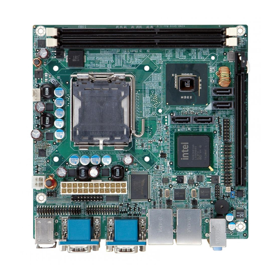
The LGA775 socket accepts Intel® Core™2 Duo/Quad/Extreme processors and the card supports two DDR3 DIMMs up to 2.0 GB each (4.0 GB total). The KINO-G410 includes VGA output and an optional 24-bit LVDS output. One PCIe x16 expansion card may be added. -
Page 16: Connectors
Six serial ports Support 24-bit LVDS by the optional VGA to LVDS converter module 1.4 Co n n e c to rs The connectors on the KINO-G410 are shown in the figure below. Figure 1-2: Connectors P a g e 3... -
Page 17: Dimensions
KINO-G410 Min i-ITX Mo th e rb o a rd 1.5 Dim e n s io n s The main dimensions of the KINO-G410 are shown in the diagram below. Figure 1-3: Dimensions (mm) P a g e 4... -
Page 18: Data Flow
KINO-G410 Min i-ITX Mo th e rb o a rd 1.6 Da ta Flo w Figure 1-4 shows the data flow between the system chipset, the CPU and other components installed on the motherboard. Figure 1-4: Data Flow Diagram P a g e 5... -
Page 19: Technical Specifications
KINO-G410 Min i-ITX Mo th e rb o a rd 1.7 Te c h n ic a l Sp e c ific a tio n s KINO-G410 technical specifications are shown below. S p e c ific a tio n s... -
Page 20: Table 1-1: Technical Specifications
KINO-G410 Min i-ITX Mo th e rb o a rd Five RS-232 COM connectors S e ria l P o rts One RS-232/422/485 COM connector Four internal via pin header US B 2.0/1.1 p o rts Four external USB ports... -
Page 21: Packing List
KINO-G410 Min i-ITX Mo th e rb o a rd Ch a p te r P a c kin g Lis t P a g e 8... -
Page 22: Anti - Static Precautions
KINO-G410 Min i-ITX Mo th e rb o a rd 2.1 An ti-s ta tic P re c a u tio n s WARNING! Static electricity can destroy certain electronics. Make sure to follow the ESD precautions to prevent damage to the product, and injury to the user. -
Page 23: Packing List
NOTE: If any of the components listed in the checklist below are missing, do not proceed with the installation. Contact the IEI reseller or vendor the KINO-G410 was purchased from or contact an IEI sales representative directly by sending an email to sales@iei.com.tw. -
Page 24: Optional Items
KINO-G410 Min i-ITX Mo th e rb o a rd 2.4 Op tio n a l Ite m s The following are optional components which may be separately purchased: Ite m a n d P a rt Nu m b e r... -
Page 25: Table 2-2: Optional Items
KINO-G410 Min i-ITX Mo th e rb o a rd Ite m a n d P a rt Nu m b e r Im a g e SATA power cable (P/N: 32100-088600-RS 32102-000100-100-RS 32102-000100-200-RS) VGA to LVDS (24-bit) converter module... -
Page 26: Connectors
KINO-G410 Min i-ITX Mo th e rb o a rd Ch a p te r Co n n e c to rs P a g e 13... -
Page 27: Peripheral Interface Connectors
KINO-G410 Min i-ITX Mo th e rb o a rd 3.1 P e rip h e ra l In te rfa c e Co n n e c to rs This chapter details all the jumpers and connectors. 3.1.1 La yo u t The figure below shows all the connectors and jumpers. -
Page 28: Peripheral Interface Connectors
KINO-G410 Min i-ITX Mo th e rb o a rd 3.1.2 P e rip h e ra l In te rfa c e Co n n e c to rs The table below lists all the connectors on the board. -
Page 29: Internal Peripheral Connectors
KINO-G410 Min i-ITX Mo th e rb o a rd Co n n e c to r Typ e La b e l Audio connector Audio jack AUDIO_CV1 Keyboard/Mouse connector PS/2 KBMS1 LAN connector RJ-45 LAN1, LAN2 Serial port connector... -
Page 30: Cpu Fan Connector
KINO-G410 Min i-ITX Mo th e rb o a rd Description Battery+ (+3V) Ground Table 3-3: Battery Connector Pinouts 3.2.2 CP U Fa n Co n n e c to r CN La b e l: CP U_FAN1 4-pin wafer... -
Page 31: System Fan Connector
KINO-G410 Min i-ITX Mo th e rb o a rd 3.2.3 S ys te m Fa n Co n n e c to r CN La b e l: S YS _FAN1 3-pin wafer CN Typ e : CN Lo c a tio n :... -
Page 32: Digital I/O Connector
KINO-G410 Min i-ITX Mo th e rb o a rd Figure 3-5: CPU Power Input Connector Location Description +12 V +12 V Table 3-6: CPU Power Input Connector Pinouts 3.2.5 Dig ita l I/O Co n n e c to r... -
Page 33: Front Panel Connector
KINO-G410 Min i-ITX Mo th e rb o a rd Description Description VCC5S Output 3 Output 2 Output 1 Output 0 Input 3 Input 2 Input 1 Input 0 Table 3-7: Digital I/O Connector Pinouts 3.2.6 Fro n t P a n e l Co n n e c to r... -
Page 34: Memory Slot
KINO-G410 Min i-ITX Mo th e rb o a rd FUNCTION DESCRIPTION FUNCTION DESCRIPTION Power LED LED+ Buzzer BEEP_PWR LED- Power BUTTON1 PC_BEEP Button BUTTON2 HDD LED HDD LED+ Reset RESET HDD LED- Table 3-8: Front Panel Connector Pinouts 3.2.7 Me m o ry S lo t... -
Page 35: Figure 3-9: Parallel Port Connector Location
KINO-G410 Min i-ITX Mo th e rb o a rd CN Lo c a tio n : See Figure 3-9 See Table 3-9 CN P in o u ts : The parallel port connector connects to a parallel port connector interface or some other parallel port device such as a printer. -
Page 36: Power Connector
KINO-G410 Min i-ITX Mo th e rb o a rd 3.2.9 P o we r Co n n e c to r CN La b e l: ATX1 24-pin connector CN Typ e : CN Lo c a tio n :... -
Page 37: Serial Port Connector
KINO-G410 Min i-ITX Mo th e rb o a rd 3.2.10 RS -232 S e ria l P o rt Co n n e c to r CN La b e l: COM4, COM5 10-pin header CN Typ e :... -
Page 38: Rs-232/422/485 Serial Port Connector
KINO-G410 Min i-ITX Mo th e rb o a rd 3.2.11 RS -232/422/485 S e ria l P o rt Co n n e c to r CN La b e l: COM6 14-pin header CN Typ e : CN Lo c a tio n :... -
Page 39: Sata Drive Connectors
KINO-G410 Min i-ITX Mo th e rb o a rd 3.2.12 S ATA Drive Co n n e c to rs CN La b e l: S ATA1, S ATA2, S ATA3, S ATA4 7-pin SATA drive connectors CN Typ e :... -
Page 40: Spi Flash Connector
KINO-G410 Min i-ITX Mo th e rb o a rd Figure 3-14: SMBus Connector Location Description SDAT SCLK Table 3-13: SMBus Connector Pinouts 3.2.14 S P I Fla s h Co n n e c to r CN La b e l:... -
Page 41: Usb Connectors
KINO-G410 Min i-ITX Mo th e rb o a rd Description Description +3.3V CLOCK Table 3-14: SPI Flash Connector 3.2.15 US B Co n n e c to rs CN La b e l: US B45, US B67 8-pin header... -
Page 42: Vga To Lvds Connector
KINO-G410 Min i-ITX Mo th e rb o a rd 3.2.16 VGA to LVDS Co n n e c to r CN La b e l: J P 4 20-pin header CN Typ e : CN Lo c a tio n :... -
Page 43: External Peripheral Interface Connector Panel
KINO-G410 Min i-ITX Mo th e rb o a rd 3.3 Exte rn a l P e rip h e ra l In te rfa c e Co n n e c to r P a n e l The figure below shows the external peripheral interface connector (EPIC) panel. The... -
Page 44: Keyboard/Mouse Connector
KINO-G410 Min i-ITX Mo th e rb o a rd 3.3.2 Ke yb o a rd /Mo u s e Co n n e c to r CN La b e l: KBMS 1 PS/2 CN Typ e : CN Lo c a tio n :... -
Page 45: Serial Port Connectors (Com1, Com2 And Com3)
KINO-G410 Min i-ITX Mo th e rb o a rd Description Description MDIA3- MDIA1+ MDIA3+ MDIA2+- MDIA2- MDIA0- MDIA1- MDIA0+ Table 3-18: LAN Pinouts 3.3.4 S e ria l P o rt Co n n e c to rs (COM1, COM2 a n d COM3) -
Page 46: Usb Connector
KINO-G410 Min i-ITX Mo th e rb o a rd 3.3.5 US B Co n n e c to r CN La b e l: US B01, US B23 USB port CN Typ e : CN Lo c a tio n :... -
Page 47: Table 3-21: Vga Connector Pinouts
KINO-G410 Min i-ITX Mo th e rb o a rd Description Description GREEN BLUE VCC / NC DDC DAT HSYNC VSYNC DDCCLK Table 3-21: VGA Connector Pinouts P a g e 34... -
Page 48: Installation
KINO-G410 Min i-ITX Mo th e rb o a rd Ch a p te r In s ta lla tio n P a g e 35... -
Page 49: Anti Static Precautions
Electrostatic discharge (ESD) can cause serious damage to electronic components, including the KINO-G410. Dry climates are especially susceptible to ESD. It is therefore critical that whenever the KINO-G410 or any other electrical component is handled, the following anti-static precautions are strictly adhered to. - Page 50 Turn all power to the KINO-G410 off: When working with the KINO-G410, make sure that it is disconnected from all power supplies and that no electricity is being fed into the system. Before and during the installation of the KINO-G410 DO NOT: ...
-
Page 51: Basic Installation
KINO-G410 Min i-ITX Mo th e rb o a rd 4.3 Ba s ic In s ta lla tio n This section outlines the parts that must be installed for the system to function correctly. 4.3.1 CP U In s ta lla tio n NOTE: To enable Hyper-Threading, the CPU and chipset must both support it. -
Page 52: Figure 4-2: Remove Protective Cover
KINO-G410 Min i-ITX Mo th e rb o a rd WARNING: DO NOT touch the pins at the bottom of the CPU. When handling the CPU, only hold it on the sides. S te p 1: Remove the protective cover. The black protective cover can be removed by pulling up on the tab labeled "Remove". -
Page 53: Figure 4-4: Insert The Socket Lga775 Cpu
KINO-G410 Min i-ITX Mo th e rb o a rd Inspect the CPU socket. Make sure there are no bent pins and make sure the S te p 3: socket contacts are free of foreign material. If any debris is found, remove it with compressed air. -
Page 54: Cooling Kit Installation
DO NOT use the original Intel® heat sink and fan. A proprietary one is recommended. Figure 4-5: Cooling Kits The cooling kit can be bought from IEI. The cooling kit has a heatsink and fan. WARNING: Do not wipe off (accidentally or otherwise) the pre-sprayed layer of thermal paste on the bottom of the heat sink. -
Page 55: Figure 4-6: Securing The Heat Sink To The Kino-G410
S te p 6: Connect the fan cable. Connect the cooling kit fan cable to the fan connector on the KINO-G410. Carefully route the cable and avoid heat generating chips and fan blades. S te p 0:... -
Page 56: Dimm Installation
0: 4.3.4 Mo th e rb o a rd In s ta lla tio n To install the KINO-G410 motherboard into the chassis please refer to the reference material that came with the chassis. P a g e 43... -
Page 57: Jumper Settings
KINO-G410 Min i-ITX Mo th e rb o a rd 4.4 J u m p e r S e ttin g s NOTE: A jumper is a metal bridge used to close an electrical circuit. It consists of two or... -
Page 58: Com 6 Function Select Jumper
KINO-G410 Min i-ITX Mo th e rb o a rd Description Short 1-2 Normal (Default) Short 2-3 Clear BIOS Table 4-2: Clear BIOS Jumper Settings Figure 4-8: Clear BIOS Jumper Location 4.4.2 COM 6 Fu n c tio n S e le c t J u m p e r... -
Page 59: Internal Peripheral Device Connections
This section outlines the installation of peripheral devices to the onboard connectors. 4.5.1 S ATA Drive Co n n e c tio n The KINO-G410 is shipped with two SATA drive cables and one SATA drive power cable. To connect the SATA drives to the connectors, please follow the steps below. -
Page 60: Figure 4-10: Sata Drive Cable Connection
KINO-G410 Min i-ITX Mo th e rb o a rd Figure 4-10: SATA Drive Cable Connection Connect the cable to the SATA disk. Connect the connector on the other end S te p 3: of the cable to the connector at the back of the SATA drive. See Figure 4-11. -
Page 61: Usb Cable (Dual Port) With Slot Bracket
4.5.2 US B Ca b le (Du a l P o rt) with S lo t Bra c ke t The KINO-G410 is shipped with a dual port USB 2.0 cable. To connect the USB cable connector, please follow the steps below. -
Page 62: External Peripheral Interface Connection
This section describes connecting devices to the external connectors on the KINO-G410. 4.6.1 Au d io Co n n e c to r The audio jacks on the external audio connector enable the KINO-G410 to be connected to a stereo sound setup. To install the audio devices, follow the steps below. -
Page 63: Ps/2 Keyboard And Mouse Connection
4.6.2 P S /2 Ke yb o a rd a n d Mo u s e Co n n e c tio n The KINO-G410 has a dual PS/2 connector on the external peripheral interface panel. The dual PS/2 connector is used to connect to a keyboard and mouse to the system. Follow the steps below to connect a keyboard and mouse to the KINO-G410. -
Page 64: Lan Connection
KINO-G410 Min i-ITX Mo th e rb o a rd Figure 4-14: PS/2 Keyboard/Mouse Connector 4.6.3 LAN Co n n e c tio n There are two external RJ-45 LAN connectors. The RJ-45 connectors enable connection to an external network. To connect a LAN cable with an RJ-45 connector, please follow the instructions below. -
Page 65: Serial Device Connection
4.6.4 S e ria l De vic e Co n n e c tio n The KINO-G410 has three male DB-9 connectors on the external peripheral interface panel for a serial device. Follow the steps below to connect a serial device to the KINO-G410. -
Page 66: Usb Device Connection
4.6.5 US B De vic e Co n n e c tio n The external USB Series "A" receptacle connectors provide easier and quicker access to external USB devices. Follow the steps below to connect USB devices to the KINO-G410. Locate the USB Series "A" receptacle connectors. The location of the USB S te p 1: Series "A"... -
Page 67: Vga Monitor Connection
4.6.6 VGA Mo n ito r Co n n e c tio n The KINO-G410 has a single female DB-15 connector on the external peripheral interface panel. The DB-15 connector is connected to a CRT or VGA monitor. To connect a monitor to the KINO-G410, please follow the instructions below. -
Page 68: Software Installation
S te p 0: 4.7 S o ftwa re In s ta lla tio n All the drivers for the KINO-G410 are on the CD that came with the system. To install the drivers, please follow the steps below. S te p 1: Insert the CD into a CD drive connected to the system. -
Page 69: Bios
KINO-G410 Min i-ITX Mo th e rb o a rd Ch a p te r BIOS P a g e 56... -
Page 70: Introduction
KINO-G410 Min i-ITX Mo th e rb o a rd 5.1 In tro d u c tio n The BIOS is programmed onto the BIOS chip. The BIOS setup program allows changes to certain system settings. This chapter outlines the options that can be changed. -
Page 71: Getting Help
KINO-G410 Min i-ITX Mo th e rb o a rd Ke y Fu n c tio n F2/F3 key Change color from total 3 colors. F2 to select color forward Save all the CMOS changes, only for Main Menu Table 5-1: BIOS Navigation Keys 5.1.3 Ge ttin g He lp... -
Page 72: Main
KINO-G410 Min i-ITX Mo th e rb o a rd 5.2 Ma in The Main BIOS menu (BIOS Menu 1) appears when the BIOS Setup program is entered. The Main menu gives an overview of the basic system information. BIOS SETUP UTILITY... -
Page 73: Advanced
KINO-G410 Min i-ITX Mo th e rb o a rd The System Overview field also has two user configurable fields: S ys te m Tim e [xx:xx:xx] Use the System Time option to set the system time. Manually enter the hours, minutes and seconds. -
Page 74: Cpu Configuration
KINO-G410 Min i-ITX Mo th e rb o a rd 5.3.1 CP U Co n fig u ra tio n Use the CPU Configuration menu (BIOS Menu 3) to view detailed CPU specifications and configure the CPU. BIOS SETUP UTILITY... -
Page 75: Bios Menu 4: Ide Configuration
KINO-G410 Min i-ITX Mo th e rb o a rd BIOS SETUP UTILITY Advanced IDE Configuration Options Disabled ATA/IDE Configuration [Enhanced] Compatible Configure SATA as [IDE] Enhanced > Primary IDE Master : [Not Detected] > Primary IDE Slave : [Not Detected] ... -
Page 76: Ide Master, Ide Slave
KINO-G410 Min i-ITX Mo th e rb o a rd When entering setup, BIOS auto detects the presence of IDE devices. BIOS displays the status of the auto detected IDE devices. The following IDE devices are detected and are shown in the IDE Configuration menu: ... - Page 77 KINO-G410 Min i-ITX Mo th e rb o a rd The “grayed-out” items in the left frame are IDE disk drive parameters automatically detected from the firmware of the selected IDE disk drive. The drive parameters are listed as follows: ...
- Page 78 KINO-G410 Min i-ITX Mo th e rb o a rd BIOS does not attempt to search for other types of IDE disk drives on the specified channel. ARMD This option specifies an ATAPI Removable Media Device. These include, but are not limited to: LS-120 ...
- Page 79 KINO-G410 Min i-ITX Mo th e rb o a rd P IO Mo d e [Au to ] Use the PIO Mode option to select the IDE PIO (Programmable I/O) mode program timing cycles between the IDE drive and the programmable IDE controller. As the PIO mode increases, the cycle time decreases.
- Page 80 KINO-G410 Min i-ITX Mo th e rb o a rd MWDMA2 Multi Word DMA mode 2 selected with a maximum data transfer rate of 16.6MBps Ultra DMA mode 0 selected with a maximum data transfer UDMA1 rate of 16.6MBps ...
-
Page 81: Super Io Configuration
KINO-G410 Min i-ITX Mo th e rb o a rd Enabled Allows BIOS to use 32-bit data transfers on supported EFAULT hard disk drives. 5.3.3 S u p e r IO Co n fig u ra tio n Use the Super IO Configuration menu (BIOS Menu 6) to set or change the configurations for the serial ports. - Page 82 KINO-G410 Min i-ITX Mo th e rb o a rd Use the Serial Port1 IRQ option to select the interrupt address for serial port 1. IRQ4 Serial port 1 IRQ address is IRQ4 EFAULT IRQ3 Serial port 1 IRQ address is IRQ3 ...
- Page 83 KINO-G410 Min i-ITX Mo th e rb o a rd S e ria l P o rt4 Ad d re s s [2E8] Use the Serial Port4 Address option to select the Serial Port 4 base address. No base address is assigned to Serial Port 4 Disabled ...
-
Page 84: Ir Function [Com6]
KINO-G410 Min i-ITX Mo th e rb o a rd Serial Port 6 I/O port address is 328 EFAULT S e ria l P o rt6 IRQ [IRQ10] Use the Serial Port6 IRQ option to select the interrupt address for serial port 6. -
Page 85: Parallel Port Irq [Irq7]
KINO-G410 Min i-ITX Mo th e rb o a rd Normal The normal parallel port mode is the standard mode EFAULT for parallel port operation. Parallel port outputs are 8-bits long. Inputs are Bi-Directional accomplished by reading 4 of the 8 bits on the status register. -
Page 86: Hardware Health Configuration
KINO-G410 Min i-ITX Mo th e rb o a rd 5.3.4 Ha rd wa re He a lth Co n fig u ra tio n The Hardware Health Configuration menu (BIOS Menu 7) shows the operating temperature, fan speed and system voltages. - Page 87 KINO-G410 Min i-ITX Mo th e rb o a rd CP U FAN1 Mo d e S e ttin g [Au to Fa n b y RP M] Use the CPU FAN1 Mode Setting option to configure the CPU Fan.
-
Page 88: Sys Fan1 Second / Third / Fourth / Lowest Setting [N]
KINO-G410 Min i-ITX Mo th e rb o a rd Manual Mode The fan spins at the speed set in Manual Mode by by RPM RPM settings The fan spins at the speed set in Manual Mode by... -
Page 89: Power Configuration
KINO-G410 Min i-ITX Mo th e rb o a rd VBAT 5.3.5 P o we r Co n fig u ra tio n The Power Configuration menu (BIOS Menu 8) configures the Advanced Configuration and Power Interface (ACPI) and Power Management (APM) options. -
Page 90: Acpi Configuration
KINO-G410 Min i-ITX Mo th e rb o a rd 5.3.5.1 ACP I c o n fig u ra tio n The ACPI Configuration menu (BIOS Menu 9) configures the Advanced Configuration and Power Interface (ACPI). BIOS SETUP UTILITY Advanced... -
Page 91: Bios Menu 10: Advanced Power Management Configuration
KINO-G410 Min i-ITX Mo th e rb o a rd BIOS SETUP UTILITY Advanced APM Configuration If the AT/ATX power been set to AT mode, this item will be Restore on AC Power Loss [Last State] changed to “power on”... -
Page 92: Remote Access Configuration
KINO-G410 Min i-ITX Mo th e rb o a rd RTC Alarm Date (Days) System Time After setting the alarm, the computer turns itself on from a suspend state when the alarm goes off. 5.3.6 Re m o te Ac c e s s Co n fig u ra tio n Use the Remote Access Configuration menu (BIOS Menu 11) to configure remote access parameters. - Page 93 KINO-G410 Min i-ITX Mo th e rb o a rd Serial Port Mode Redirection after BIOS POST Terminal Type These configuration options are discussed below. When the Remote Access option is set to Enabled, the following sub-menus appear. Serial port number ...
- Page 94 KINO-G410 Min i-ITX Mo th e rb o a rd Use the Serial Port Mode option to select baud rate through which the console redirection is made. The following configuration options are available 115200 8,n,1 D EFAULT 57600 8,n,1 ...
-
Page 95: Usb Configuration
KINO-G410 Min i-ITX Mo th e rb o a rd 5.3.7 US B Co n fig u ra tio n Use the USB Configuration menu (BIOS Menu 12) to read USB configuration information and configure the USB settings. BIOS SETUP UTILITY... -
Page 96: Pci/P N P
KINO-G410 Min i-ITX Mo th e rb o a rd Normally if this option is not enabled, any attached USB mouse or USB keyboard does not become available until a USB compatible operating system is fully booted with all USB drivers loaded. -
Page 97: Bios Menu 13: Pci/Pnp Configuration
KINO-G410 Min i-ITX Mo th e rb o a rd BIOS SETUP UTILITY Main Advanced PCIPnP Boot Security Chipset Exit Advanced PCI/PnP Settings Available: Specified IRQ is available to be used by PCI/PnP WARNING: Setting wrong values in below sections devices may cause system to malfunction. - Page 98 KINO-G410 Min i-ITX Mo th e rb o a rd IRQ9 IRQ10 IRQ 11 IRQ 14 IRQ 15 DMA Ch a n n e l# [Ava ila b le ] Use the DMA Channel# option to assign a specific DMA channel to a particular PCI/PnP device.
-
Page 99: Boot
KINO-G410 Min i-ITX Mo th e rb o a rd 5.5 Bo o t Use the Boot menu (BIOS Menu 14) to configure system boot options. BIOS SETUP UTILITY Main Advanced PCIPnP Boot Security Chipset Exit Boot Settings Configure settings ... -
Page 100: Bootup Num-Lock [On]
KINO-G410 Min i-ITX Mo th e rb o a rd Qu ic k Bo o t [En a b le d ] Use the Quick Boot BIOS option to make the computer speed up the boot process. No POST procedures are skipped Disabled ... -
Page 101: Security
KINO-G410 Min i-ITX Mo th e rb o a rd automatically when the computer system boots up. This allows the immediate use of the 10-key numeric keypad located on the right side of the keyboard. To confirm this, the Number Lock LED light on the keyboard is lit. - Page 102 KINO-G410 Min i-ITX Mo th e rb o a rd this field and enter the password. After the password has been added, Install appears next to Change Supervisor Password. Ch a n g e Us e r P a s s wo rd Use the Change User Password to set or change a user password.
-
Page 103: Chipset
KINO-G410 Min i-ITX Mo th e rb o a rd 5.7 Ch ips e t Use the Chipset menu (BIOS Menu 17) to access the NorthBridge and SouthBridge configuration menus. WARNING! Setting the wrong values for the Chipset BIOS selections in the Chipset BIOS menu may cause the system to malfunction. -
Page 104: Bios Menu 18: North Bridge Chipset Configuration
KINO-G410 Min i-ITX Mo th e rb o a rd BIOS SETUP UTILITY Chipset North Bridge Chipset Configuration Options Disabled Memory Hole [Disabled] 15MB-16MB Initate Graphic Adapter [PEG/IGD] Internal Graphics Mode Select [Enabled, 32MB] Boot Display Device [CRT] ... -
Page 105: South Bridge Chipset Configuration
KINO-G410 Min i-ITX Mo th e rb o a rd Disabled 32MB of memory used by internal graphics device Enabled, 32MB EFAULT Enabled, 64MB 64MB of memory used by internal graphics device Enabled, 128MB 128MB of memory used by internal graphics device ... -
Page 106: Exit
KINO-G410 Min i-ITX Mo th e rb o a rd Auto The on-board audio controller is detected and EFAULT automatically enabled. The on-board audio controller is disabled. Disabled Sp re a d Sp e c tru m Fu n c tio n [Dis a b le d ] Use the Spread Spectrum Function option to reduce the EMI. - Page 107 KINO-G410 Min i-ITX Mo th e rb o a rd Use the Save Changes and Exit option to save the changes made to the BIOS options and to exit the BIOS configuration setup program. Dis c a rd Ch a n g e s a n d Exit Use the Discard Changes and Exit option to exit the BIOS configuration setup program without saving the changes made to the system.
-
Page 108: A Bios Options
KINO-G410 Min i-ITX Mo th e rb o a rd Ap p e n d ix BIOS Op tio n s P a g e 95... - Page 109 KINO-G410 Min i-ITX Mo th e rb o a rd Below is a list of BIOS configuration options in the BIOS chapter. System Overview ......................... 59 System Time [xx:xx:xx] ....................... 60 System Date [xx/xx/xx] ......................60 ...
- Page 110 KINO-G410 Min i-ITX Mo th e rb o a rd CPU Fan1 Highest Setting [100] ..................74 CPU Fan1 Second / Third / Fourth / Lowest Setting [n] ........... 74 SYS FAN1 Mode Setting [Auto Fan by RPM] ..............74 ...
- Page 111 KINO-G410 Min i-ITX Mo th e rb o a rd Audio Controller [Auto] ....................... 92 Spread Spectrum Function [Disabled] ................93 Save Changes and Exit ....................... 93 Discard Changes and Exit ....................94 Discard Changes ........................94 ...
-
Page 112: B Terminology
KINO-G410 Min i-ITX Mo th e rb o a rd Ap p e n d ix Te rm in o lo g y P a g e 99... - Page 113 KINO-G410 Min i-ITX Mo th e rb o a rd AC ’97 Audio Codec 97 (AC’97) refers to a codec standard developed by Intel® in 1997. Advanced Configuration and Power Interface (ACPI) is an OS-directed ACP I configuration, power management, and thermal management interface.
- Page 114 KINO-G410 Min i-ITX Mo th e rb o a rd DIMM Dual Inline Memory Modules are a type of RAM that offer a 64-bit data bus and have separate electrical contacts on each side of the module. The digital inputs and digital outputs are general control signals that control the on/off circuit of external devices or TTL devices.
- Page 115 KINO-G410 Min i-ITX Mo th e rb o a rd LVDS Low-voltage differential signaling (LVDS) is a dual-wire, high-speed differential electrical signaling system commonly used to connect LCD displays to a computer. P OS T The Power-on Self Test (POST) is the pre-boot actions the system performs when the system is turned-on.
-
Page 116: C One Key Recovery
KINO-G410 Min i-ITX Mo th e rb o a rd Ap p e n d ix On e Ke y Re c o ve ry P a g e 103... -
Page 117: One Key Recovery Introduction
The IEI One Key Recovery tool menu is shown below. Figure C-1: IEI One Key Recovery Tool Menu Prior to using the IEI One Key Recovery tool (as shown in Figure C-1) to backup or restore Windows system, five setup procedures are required. -
Page 118: System Requirement
C.1.1 S ys te m Re q u ire m e n t NOTE: The recovery CD can only be used with IEI products. The software will fail to run and a warning message will appear when used on non-IEI hardware. -
Page 119: Supported Operating System
KINO-G410 Min i-ITX Mo th e rb o a rd NOTE: Specialized tools are required to change the partition size if the operating system is already installed. C.1.2 S u p p o rte d Op e ra tin g S ys te m The recovery CD is compatible with both Microsoft Windows and Linux operating system (OS). -
Page 120: Setup Procedure For Windows
KINO-G410 Min i-ITX Mo th e rb o a rd NOTE: Installing unsupported OS versions may cause the recovery tool to fail. C.2 S e tu p P ro c e d u re fo r Win d o ws Prior to using the recovery tool to backup or restore Windows system, a few setup procedures are required. -
Page 121: Create Partitions
KINO-G410 Min i-ITX Mo th e rb o a rd Turn on the system. S te p 4: Press the <DELETE> key as soon as the system is turned on to enter the BIOS. S te p 5: boot device. (Boot Boot... -
Page 122: Figure C-3: Recovery Tool Setup Menu
KINO-G410 Min i-ITX Mo th e rb o a rd The recovery tool setup menu is shown as below. S te p 3: Figure C-3: Recovery Tool Setup Menu S te p 4: Press <5> then <Enter>. Figure C-4: Command Mode S te p 5: The command prompt window appears. -
Page 123: Figure C-5: Partition Creation Commands
KINO-G410 Min i-ITX Mo th e rb o a rd system32>format F: /fs:ntfs /q /v:Recovery /y system32>exit Figure C-5: Partition Creation Commands P a g e 110... -
Page 124: Install Operating System, Drivers And Applications
KINO-G410 Min i-ITX Mo th e rb o a rd NOTE: Use the following commands to check if the partitions were created successfully. Press any key to exit the recovery tool and automatically reboot the system. S te p 6: Please continue to the following procedure: Build-up Recovery Partition.S t e p 0 :... -
Page 125: Build-Up Recovery Partition
KINO-G410 Min i-ITX Mo th e rb o a rd C.2.4 Bu ild -u p Re c o ve ry P a rtitio n Put the recover CD in the optical drive. S te p 1: S te p 2: Start the system. -
Page 126: Figure C-8: Build-Up Recovery Partition
KINO-G410 Min i-ITX Mo th e rb o a rd recovery files in Section C.2.2 is hidden and the recovery tool is saved in this partition. Figure C-8: Build-up Recovery Partition S te p 6: After completing the system configuration, press any key in the following window to reboot the system. -
Page 127: Create Factory Default Image
KINO-G410 Min i-ITX Mo th e rb o a rd C.2.5 Cre a te Fa c to ry De fa u lt Im a g e NOTE: Before creating the factory default image, please configure the system to a factory default environment, including driver and application installations. -
Page 128: Figure C-12: About Symantec Ghost Window
KINO-G410 Min i-ITX Mo th e rb o a rd Figure C-12: About Symantec Ghost Window Use mouse to navigate to the option shown below (Figure C-13). S te p 4: Figure C-13: Symantec Ghost Path Select the local source drive (Drive 1) as shown in Figure C-14. Then click OK. -
Page 129: Figure C-14: Select A Local Source Drive
KINO-G410 Min i-ITX Mo th e rb o a rd Figure C-14: Select a Local Source Drive S te p 6: Select a source partition (Part 1) from basic drive as shown in Figure C-15. Then click OK. Figure C-15: Select a Source Partition from Basic Drive Select 1.2: [Recovery] NTFS drive and enter a file name called... -
Page 130: Figure C-16: File Name To Copy Image To
KINO-G410 Min i-ITX Mo th e rb o a rd Figure C-16: File Name to Copy Image to When the Compress Image screen in Figure C-17 prompts, click High to make S te p 8: the image file smaller. Figure C-17: Compress Image... -
Page 131: Figure C-18: Image Creation Confirmation
KINO-G410 Min i-ITX Mo th e rb o a rd The Proceed with partition image creation window appears, click Yes to S te p 9: continue. Figure C-18: Image Creation Confirmation The Symantec Ghost starts to create the factory default image (Figure C-19). -
Page 132: Setup Procedure For Linux
KINO-G410 Min i-ITX Mo th e rb o a rd The recovery tool main menu window is shown as below. Press any key to S te p 12: reboot the system. S t e p 0 : Figure C-21: Press Any Key to Continue C.3 S e tu p P ro c e d u re fo r Lin u x... -
Page 133: Figure C-22: Partitions For Linux
KINO-G410 Min i-ITX Mo th e rb o a rd NOTE: Please reserve enough space for partition 3 for saving recovery images. Figure C-22: Partitions for Linux S te p 3: Create a recovery partition. Insert the recovery CD into the optical disk drive. -
Page 134: Figure C-23: System Configuration For Linux
KINO-G410 Min i-ITX Mo th e rb o a rd Figure C-23: System Configuration for Linux S te p 5: Access the recovery tool main menu by modifying the “menu.lst”. To first access the recovery tool main menu, the menu.lst must be modified. In Linux system, enter Administrator (root). -
Page 135: Recovery Tool Functions
KINO-G410 Min i-ITX Mo th e rb o a rd S te p 7: The recovery tool menu appears. (Figure C-25) Figure C-25: Recovery Tool Menu Create a factory default image. Follow Step 2 Step 12 described in S te p 8: Section C.2.5 to create a factory default image. -
Page 136: Figure C-26: Recovery Tool Main Menu
KINO-G410 Min i-ITX Mo th e rb o a rd Figure C-26: Recovery Tool Main Menu The recovery tool has several functions including: 1. Factory Restore: Restore the factory default image (iei.GHO) created in Section C.2.5. 2. Backup system: Create a system backup image (iei_user.GHO) which will be saved in the hidden partition. -
Page 137: Factory Restore
Type <1> and press <Enter> in the main menu. The Symantec Ghost window appears and starts to restore the factory default. A S te p 2: factory default image called iei.GHO is created in the hidden Recovery partition. Figure C-27: Restore Factory Default S te p 3: The screen is shown as in Figure C-28 when completed. -
Page 138: Backup System
KINO-G410 Min i-ITX Mo th e rb o a rd C.4.2 Ba c ku p S ys te m To backup the system, please follow the steps below. S te p 1: Type <2> and press <Enter> in the main menu. -
Page 139: Restore Your Last Backup
KINO-G410 Min i-ITX Mo th e rb o a rd C.4.3 Re s to re Yo u r La s t Ba c ku p To restore the last system backup, please follow the steps below. S te p 1: Type <3>... -
Page 140: Manual
KINO-G410 Min i-ITX Mo th e rb o a rd C.4.4 Ma n u a l To restore the last system backup, please follow the steps below. S te p 1: Type <4> and press <Enter> in the main menu. -
Page 141: Other Information
KINO-G410 Min i-ITX Mo th e rb o a rd C.5 Oth e r In fo rm a tio n C.5.1 Us in g AHCI Mo d e o r ALi M5283 / VIA VT6421A Co n tro lle r... - Page 142 KINO-G410 Min i-ITX Mo th e rb o a rd When the following window appears, press <S> to select “Specify Additional S te p 5: Device”. In the following window, select a SATA controller mode used in the system. Then S te p 6: press <Enter>.
-
Page 143: System Memory Requirement
KINO-G410 Min i-ITX Mo th e rb o a rd After pressing <Enter>, the system will get into the recovery tool setup menu. S te p 7: Continue to follow the setup procedure from Step 4 in Section C.2.2 Create Partitions to finish the whole setup process. -
Page 144: D Watchdog Timer
KINO-G410 Min i-ITX Mo th e rb o a rd Ap p e n d ix Wa tc h d o g Tim e r P a g e 131... - Page 145 KINO-G410 Min i-ITX Mo th e rb o a rd NOTE: The following discussion applies to DOS. Contact IEI support or visit the IEI website for drivers for other operating systems. The Watchdog Timer is a hardware-based timer that attempts to restart the system when it stops working.
- Page 146 KINO-G410 Min i-ITX Mo th e rb o a rd NOTE: The Watchdog Timer is activated through software. The software application that activates the Watchdog Timer must also deactivate it when closed. If the Watchdog Timer is not deactivated, the system will automatically restart after the Timer has finished its countdown.
-
Page 147: E Digital I/O Interface
KINO-G410 Min i-ITX Mo th e rb o a rd Ap p e n d ix Dig ita l I/O In te rfa c e P a g e 134... -
Page 148: Introduction
KINO-G410 Min i-ITX Mo th e rb o a rd E.1 In tro d u c tio n The digital I/O is used for machine control and automation. E.2 DIO Co n n e c to r P in o u ts Located in the Connectors section of this document. -
Page 149: F Hazardous Materials Disclosure
KINO-G410 Min i-ITX Mo th e rb o a rd Ap p e n d ix Ha za rd o u s Ma te ria ls Dis c lo s u re P a g e 136... -
Page 150: Hazardous Materials Disclosure Table For Ipb Products Certified As R Ohs Compliant Under 2002/95/Ec Without Mercury
KINO-G410 Min i-ITX Mo th e rb o a rd F.1 Ha za rd o u s Ma te ria ls Dis c lo s u re Ta b le fo r IP B P ro d u c ts... - Page 151 KINO-G410 Min i-ITX Mo th e rb o a rd P a rt Na m e To xic o r Ha za rd o u s S u b s ta n c e s a n d Ele m e n ts...
- Page 152 KINO-G410 Min i-ITX Mo th e rb o a rd 此附件旨在确保本产品符合中国 RoHS 标准。以下表格标示此产品中某有毒物质的含量符 合中国 RoHS 标准规定的限量要求。 本产品上会附有”环境友好使用期限”的标签,此期限是估算这些物质”不会有泄漏或突变”的 年限。本 产品可能包含有较短的环境友好使用期限的可替换元件,像是电池或灯管,这些元 件将会单独标示出来。 部件名称 有毒有害物质或元素 铅 汞 镉 六价铬 多溴联苯 多溴二苯 醚 (P b ) (Hg ) (Cd ) (CR(VI)) (P BB) (P BDE) 壳体...
Need help?
Do you have a question about the Kino-g410 and is the answer not in the manual?
Questions and answers