Advertisement
Quick Links
Advertisement

Related Manuals for IEI Technology KINO-6614


Summary of Contents for IEI Technology KINO-6614
- Page 1 KINO-6614 Motherboard KINO-6614 Motherboard User Manual...
- Page 2 REVISION HISTORY Title KINO-6614 Intel Pentium 4 Motherboard Revision Number Description Date of Issue Initial release November 2006 COPYRIGHT NOTICE The information in this document is subject to change without prior notice in order to improve reliability, design and function and does not represent a commitment on the part of the manufacturer.
-
Page 3: Table Of Contents
................... 16 VERVIEW 1.1.1 KINO-6614 Benefits..................16 1.1.2 KINO-6614 Features..................16 1.2 KINO-6614 B ................17 OARD VERVIEW 1.2.1 KINO-6614 Connectors ................... 17 1.2.2 Technical Specifications................... 18 DETAILED SPECIFICATIONS ................21 2.1 O ....................... 22 VERVIEW 2.2 CPU S ......................22 UPPORT ®... -
Page 4: Table Of Contents
2.18.2 Optional Accessory Items................30 CONNECTORS AND JUMPERS ................. 33 3.1 P ..............34 ERIPHERAL NTERFACE ONNECTORS 3.1.1 KINO-6614 Layout................... 34 3.1.2 Peripheral Interface Connectors ..............35 3.1.3 Rear Panel Connectors ..................36 3.1.4 On-board Jumpers ................... 36 3.2 I ..............37 NTERNAL... -
Page 5: Table Of Contents
KINO-6614 Motherboard 4.3.1 Unpacking Precautions..................59 4.3.2 Checklist......................60 4.4 KINO-6614 ............60 MOTHERBOARD NSTALLATION 4.5 S LGA775 CPU I ..............61 OCKET NSTALLATION 4.5.1 CPU Selection: HT Functionality Requirements ..........61 4.5.1.1 CPU Installation..................61 4.5.2 Socket LGA775 Cooling Kit Installation ............64 4.5.3 DIMM Module Installation ................ -
Page 6: Table Of Contents
5.3.2 IDE Configuration ................... 83 5.3.2.1 IDE Master, IDE Slave ................86 5.3.3 Floppy Configuration..................91 5.3.4 Super IO Configuration..................92 5.3.5 Hardware Health Configuration..............95 5.3.6 ACPI Configuration ..................96 5.3.6.1 Advanced ACPI Configuration ..............97 5.3.7 MPS Configuration ..................98 5.3.8 USB Configuration................... -
Page 7: Table Of Contents
KINO-6614 Motherboard C.2 1 MB M ................. 163 EMORY DDRESS C.3 IRQ M .................... 164 APPING ABLE C.4 DMA C ................164 HANNEL SSIGNMENTS EXTERNAL AC’97 AUDIO CODEC ..............166 D.1 I ..................... 167 NTRODUCTION D.1.1 Accessing the AC’97 CODEC ............... 167 D.1.2 Driver Installation.................. -
Page 8: Table Of Contents
Figure 3-10: SATA Drive Connector Locations............46 Figure 3-11: SMBus Connector Location..............47 Figure 3-12: Internal USB Connector Locations ............48 Figure 3-13: KINO-6614 External Interface Connectors ..........49 Figure 3-14: Audio Connector..................49 Figure 3-15: RJ-45 Ethernet Connector ..............50 Figure 3-16: Ethernet Connector and USB Ports Pinout Locations ......51 Figure 3-17: PS/2 Pinouts...................52... -
Page 9: Table Of Contents
KINO-6614 Motherboard Figure 4-8: Locking the DIMM Module ..............68 Figure 4-9: Connection of IDE Connector ..............69 Figure 4-10: Connection of SATA Connector............71 Figure 4-11: Connection of a USB Connector............71 Figure 4-12 Jumper .....................72 Figure 4-13: Jumper Location..................73 Figure 6-1: SIS Solution CD Main Menu..............129 Figure 6-2: CD VGA Folder.................. -
Page 10: Table Of Contents
Figure 6-28: Starting Install Shield Wizard ............145 Figure 6-29: Preparing Setup .................. 145 Figure 6-30: Install Shield..................146 Figure 6-31: License Agreement................147 Figure 6-32: Install Application Directory .............. 148 Figure 6-33: Select Needed Components .............. 149 Figure 6-34: Ready to Install ................... 150 Figure 6-35: Setup Status.................. -
Page 11: Table Of Contents
KINO-6614 Motherboard List of Tables Table 1-1: Technical Specifications ................19 Table-2-1: Supported CPUs..................22 Table 2-2: Power Consumption .................30 Table 3-1: Peripheral Interface Connectors..............36 Table 3-2: Rear Panel Connectors................36 Table 3-3: On-board Jumper ..................36 Table 3-4: Power Connector Pinouts ................38 Table 3-5: CPU 12V Power Connector Pinouts ............38 Table 3-6: Digital I/O Connector Pinouts ..............39... -
Page 12: Table Of Contents
List of BIOS Menus BIOS Menu 1: Main......................79 BIOS Menu 2: Advanced.....................81 BIOS Menu 3: CPU Configuration................82 BIOS Menu 4: IDE Configuration ................83 BIOS Menu 5: IDE Master and IDE Slave Configuration..........87 BIOS Menu 6: Floppy Configuration .................91 BIOS Menu 7: Super IO Configuration ..............92 BIOS Menu 8: Hardware Health Configuration............95 BIOS Menu 9: ACPI Configuration................96 BIOS Menu 10: Advanced ACPI Configuration ............97... - Page 13 KINO-6614 Motherboard Glossary AC ’97 Audio Codec 97 Hard Disk Drive ACPI Advanced Configuration and Integrated Data Electronics Power Interface Input/Output Advanced Power Management ICH4 I/O Controller Hub 4 ARMD ATAPI Removable Media Device L1 Cache Level 1 Cache ASKIR...
- Page 14 KINO-6614 Motherboard THIS PAGE IS INTENTIONALLY LEFT BLANK IEI ® Technology, Corp.
-
Page 15: Introduction
KINO-6614 Motherboard Chapter Introduction... -
Page 16: Kino-6614 O Verview
KINO-6614 Motherboard 1.1 KINO-6614 Overview The Mini-ITX form factor KINO-6614 with Pentium 4 / Celeron D CPU platform is fully equipped with latest technology and advanced multi-mode I/Os. The KINO-6614 is designed for system manufacturers, integrators, and VARs that want performance, reliability, and quality at a reasonable price. -
Page 17: Kino-6614 B Oard O Verview 1.2.1 Kino-6614 Connectors
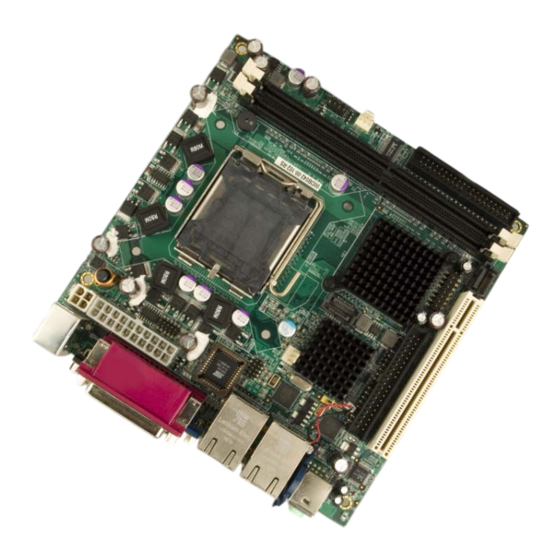
KINO-6614 Motherboard 1.2 KINO-6614 Board Overview Figure 1-1: KINO-6614 Board Overview 1.2.1 KINO-6614 Connectors The KINO-6614 has the following connectors on-board: 1 x ATX power connector 1 x CPU power connector 2 x DDR DIMM sockets 1 x Digital I/O connector... -
Page 18: Technical Specifications
The location of these connectors on the motherboard can be seen in Figure 1-1. These connectors are fully described in Chapter 3. 1.2.2 Technical Specifications KINO-6614 technical specifications are listed in Table 1-1. Detailed descriptions of each specification can be found in Chapter 2 Detailed Specifications. SPECIFICATION ®... -
Page 19: Table 1-1: Technical Specifications
KINO-6614 Motherboard Display Memory Dual channel DDR 400/333MHz memory modules (Max. 2GB) PCI Bus Interface 33MHz, Revision 2.3 Serial ATA (SATA) Four SATA connectors with 1.5Gb/s transfer rates Two IDE channels support four Ultra ATA 100 devices HDD Interface USB Interfaces Eight USB 2.0 connectors supported... - Page 20 KINO-6614 Motherboard THIS PAGE IS INTENTIONALLY LEFT BLANK IEI ® Technology, Corp.
-
Page 21: Detailed Specifications
KINO-6614 Motherboard Chapter Detailed Specifications... -
Page 22: O Verview
KINO-6614 Motherboard 2.1 Overview This chapter describes the specifications and on-board features of the KINO-6614 in detail. 2.2 CPU Support Table-2-1 lists the CPUs supported by the KINO-6614 board. Model Clock Speed L2 Cache FSB Architecture Intel ® Pentium ® 4 processor 651 3.40 GHz... -
Page 23: On-Board Chipset
KINO-6614 Motherboard giving the core faster access to larger amounts of the data used most often. Streaming SIMD Extensions Accelerates performance on a wide variety of applications including multimedia, video and audio. Minimize the acoustic noise levels generated from running the fan at higher speed for thermal performance. -
Page 24: Sis966 Southbridge Chipset
KINO-6614 Motherboard 2.3.3 SiS966 Southbridge Chipset The SiS966 southbridge chipset comes with the following features: SiS MuTIOL® 1G Delivering 1GB/s Bandwidth - Proprietary Interconnect between SiS north bridge and SiS966 - Bi-Directional 16 bit Data Bus at 133MHz x4 mode Integrated Serial Host Controller - Provides 4 independent ports for SATA, compliant with Serial ATA 1.0... -
Page 25: Data Flow
KINO-6614 Motherboard 2.4 Data Flow Figure 2-1 shows the data flow between the two onboard chipsets and other components installed on the Motherboard and described in the following sections of this chapter. Figure 2-1: Data Flow Block Diagram... -
Page 26: G Raphics S Upport
Graphics support mode CRT highest resolution mode: 2048x1536x32@75NI 2.6 Memory Support The KINO-6614 has two 184-pin DDR DIMM sockets and supports two 400MHz or 333MHz DDR DIMM with a maximum RAM of up to 2GB. 2.7 PCI Bus Interface Support The PCI bus on the KINO-6614 has the following features: 33MHz Revision 2.3 is implemented... -
Page 27: D Rive I Nterfaces
Supports Ultra ATA 33/66/100/133 devices with data transfer rates up to 133MB/s 2.9.2 SATA Drives The KINO-6614 supports four first generation SATA drives with transfer rates of up to 1.5 Gb/s. 2.10 Serial Ports The KINO-6614 has two high-speed UART serial ports. The serial ports have the following specifications. -
Page 28: Pci I Nterfaces
2.13 PCI Interfaces The KINO-6614 motherboard offers one PCI Slot Expansion Module for board expansion. 2.14 BIOS The KINO-6614 uses a licensed copy of AMI BIOS. The features of the flash BIOS used are listed below: SMIBIOS (DMI) compliant Console redirection function support... -
Page 29: Audio Codec
2.16 Audio Codec The KINO-6614 has an integrated REALTEK ALC655 CODEC. The ALC655 CODEC is a 16-bit, full-duplex AC'97 Rev. 2.3 compatible six-channel audio CODEC designed for PC multimedia systems, including host/soft audio and AMR/CNR-based designs. Some of the features of the codec are listed below. -
Page 30: P Ower C Onsumption
Configuration Panel for improved user convenience 2.17 Power Consumption Table 2-2 shows the power consumption parameters for the KINO-6614 when a Pentium 4 processor with a clock speed of 2.8GHz and 533MHz FSB is running with two DDR 400MHz 1GB DIMM modules. - Page 31 KINO-6614 Motherboard USB cable CPU cooler...
- Page 32 KINO-6614 Motherboard THIS PAGE IS INTENTIONALLY LEFT BLANK IEI ® Technology, Corp.
-
Page 33: Connectors And Jumpers
KINO-6614 Motherboard Chapter Connectors and Jumpers... -
Page 34: P Eripheral I Nterface C Onnectors
3.1 Peripheral Interface Connectors Section 3.1.1 shows peripheral interface connector locations. Section 3.1.2 lists all the peripheral interface connectors seen in Section 3.1.1. 3.1.1 KINO-6614 Layout Figure 3-1 shows the on-board peripheral connectors, backplane peripheral connectors and on-board jumpers. Figure 3-1: Connector and Jumper Locations... -
Page 35: Peripheral Interface Connectors
KINO-6614 Motherboard 3.1.2 Peripheral Interface Connectors Table 3-1 shows a list of the peripheral interface connectors on the KINO-6614. Detailed descriptions of these connectors can be found in Section 3.2. Connector Type Label ATX power connector 20-pin connector ATX20 CPU power connector... -
Page 36: Rear Panel Connectors
KINO-6614 Motherboard Table 3-1: Peripheral Interface Connectors 3.1.3 Rear Panel Connectors Table 3-2 lists the rear panel connectors on the KINO-6614. Detailed descriptions of these connectors can be found in Section 3.3. Connector Type Label Audio connector Audio Jacks AUDIO_CV1... -
Page 37: I Nternal P Eripheral C Onnectors
Internal peripheral connectors are found on the motherboard and are only accessible when the motherboard is outside of the chassis. This section has complete descriptions of all the internal, peripheral connectors on the KINO-6614. 3.2.1 ATX Power Connector CN Label:... -
Page 38: Cpu Power Connector
KINO-6614 Motherboard PIN NO. DESCRIPTION PIN NO. DESCRIPTION +5Vdc PWR-OK -5Vdc +5VSby +5Vdc +12Vdc +5Vdc Table 3-4: Power Connector Pinouts 3.2.2 CPU Power Connector CN Label: CPU12V1 CN Type: 4-pin connector (2x2) CN Location: See Figure 3-3 CN Pinouts: See Table 3-5 The connector supports the 12V power supply. -
Page 39: Digital Input/Output Connector
See Table 3-6 The DIO connector is managed through a Super I/O chip. The DIO connector pins are user programmable. The digital IO port of KINO-6614 is 5V CMOS level. Figure 3-4: Digital I/O Connector Location PIN NO. DESCRIPTION PIN NO. DESCRIPTION... -
Page 40: Front Panel Connector
CN Location: See Figure 3-5 CN Pinouts: See Table 3-7 The cooling fan connectors on the KINO-6614 provide a 12V, 500mA current to a CPU cooling fan and a system cooling fan. Figure 3-5: Fan Connector Locations PIN NO. DESCRIPTION... -
Page 41: Ide Connectors
KINO-6614 Motherboard The front panel connector connects to several external switches and indicators to monitor and control the motherboard. These indicators and switches include: Power LED ATX Power button Reset button HDD LED Figure 3-6: Front Panel Connector Location DESCRIPTION... -
Page 42: Figure 3-7: Ide Device Connector Location
KINO-6614 Motherboard One 40-pin IDE device connector on the KINO-6614 motherboard supports connectivity to ATA 133 IDE devices with data transfer rates up to 133MB/s. Figure 3-7: IDE Device Connector Location PIN NO. DESCRIPTION PIN NO. DESCRIPTION RESET# DATA 7 DATA 8 IEI ®... -
Page 43: Irda Infrared Interface Connector
KINO-6614 Motherboard PIN NO. DESCRIPTION PIN NO. DESCRIPTION DATA 6 DATA 9 DATA 5 DATA 10 DATA 4 DATA 11 DATA 3 DATA 12 DATA 2 DATA 13 DATA 1 DATA 14 DATA 0 DATA 15 IDE DRQ IOW# IOR# IDE CHRDY BALE –... -
Page 44: Serial Port Connector
KINO-6614 Motherboard Figure 3-8: IR Connector Location PIN NO. DESCRIPTION IR-RX IR-TX CIR-RX Table 3-10: IR Connector Pinouts 3.2.8 Serial Port Connector CN Label: COM2 CN Type: 10-pin header (2x5) CN Location: See Figure 3-9 CN Pinouts: See Table 3-11 The serial ports connectors connect to RS-232 serial port device. -
Page 45: Sata Drive Connectors
KINO-6614 Motherboard Figure 3-9: Serial Port Connector Location Description DATA CARRIER DETECT (DCD) RECEIVE DATA (RXD) TRANSMIT DATA (TXD) DATA TERMINAL READY (DTR) Ground (GND) DATA SET READY (DSR) REQUEST TO SEND (RTS) CLEAR TO SEND (CTS) RING INDICATOR (RI) -
Page 46: Smbus Connector
KINO-6614 Motherboard Figure 3-10: SATA Drive Connector Locations PIN NO. DESCRIPTION Table 3-12: SATA Drive Connector Pinouts 3.2.10 SMBus Connector CN Label: J_SMB1 CN Type: 4-pin header (1x4) CN Location: See Figure 3-11 CN Pinouts: See Table 3-13 The SMBus connector is a multi-device bus that permits multiple chips to work on the same bus and enables each one to act as master device by initiating data transfers. -
Page 47: Internal Usb Connectors
KINO-6614 Motherboard Figure 3-11: SMBus Connector Location PIN NO. DESCRIPTION SMBCLK SMBDATA Table 3-13: SMBus Connector Pinouts 3.2.11 Internal USB Connectors CN Label: USB46 and USB57 CN Type: 8-pin header (2x4) CN Location: See Figure 3-12 CN Pinouts: See Table 3-14 One 2x4 pin connector provides connectivity to two USB 2.0 ports. -
Page 48: E Xternal I Nterface C Onnectors
3.3 External Interface Connectors The peripheral connectors on the back panel are connected to devices externally when the KINO-6614 is installed in a chassis. The peripheral connectors on the rear panel are: 2 x Audio jacks 1 x VGA connector... -
Page 49: Audio Connectors
KINO-6614 Motherboard Figure 3-13: KINO-6614 External Interface Connectors 3.3.1 Audio Connectors CN Label: AUDIO_CV1 CN Type: Audio jack CN Location: See Figure 3-13 (labeled number 7) CN Pinouts: See Figure 3-14 Line Out port (Lime): Connects to a headphone or a speaker. With multi-channel configurations, this port can also connect to front speakers. -
Page 50: Ethernet Connectors
CN Pinouts: See Table 3-15 The KINO-6614 is equipped with two built-in GbE Ethernet controllers. The controllers can connect to the LAN through two RJ-45 LAN connectors. There are two LEDs on the connector indicating the status of LAN. The pin assignments are listed in the following... -
Page 51: Usb Connectors
KINO-6614 Motherboard SPEED LED ACT/LINK LED STATUS DESCRIPTION STATUS DESCRIPTION GREEN 100Mbps connection YELLOW Linked ORANGE 1Gbps connection BLINKING Data Activity Table 3-16: RJ-45 Ethernet Connector LEDs 3.3.3 USB Connectors CN Label: LAN1_USB01 and LAN2_USB23 CN Type: USB port CN Location:... -
Page 52: Keyboard/Mouse Connector
PS/2 connector CN Location: See Figure 3-13 (labeled number 1) CN Pinouts: See Table 3-18 and Table 3-19 The KINO-6614 keyboard and mouse connectors are standard PS/2 connectors. Figure 3-17: PS/2 Pinouts DESCRIPTION Keyboard DATA Keyboard CLOCK Table 3-18: Keyboard Connector Pinouts... -
Page 53: Serial Port Connectors
KINO-6614 Motherboard Table 3-19: Mouse Connector Pinouts 3.3.5 Serial Port Connectors CN Label: COM_C1 CN Type: D-sub 9 male connector CN Location: See Figure 3-13 (labeled number 9) CN Pinouts: See Table 3-20 The serial ports can be connected to a serial communications device directly. -
Page 54: Vga Connector
KINO-6614 Motherboard 3.3.6 VGA Connector CN Label: VGA1 CN Type: 15-pin female connector CN Location: See Figure 3-13 (labeled number 8) CN Pinouts: See Table 3-21 The standard 15-pin VGA connector connects to a CRT or LCD display monitor. Figure 3-19: VGA Connector PIN NO. -
Page 55: Figure 3-20: Parallel Connector Pinout Locations
See Figure 3-13 (labeled 2) CN Pinouts: See Figure 3-20 and Table 3-22 The KINO-6614 motherboard includes one external parallel port, accessed through 25-pin D-type female connector LPT1. These ports are usually connected to a printer. Figure 3-20: Parallel Connector Pinout Locations... - Page 56 KINO-6614 Motherboard THIS PAGE IS INTENTIONALLY LEFT BLANK IEI ® Technology, Corp.
-
Page 57: Installation And Configuration
KINO-6614 Motherboard Chapter Installation and Configuration... -
Page 58: A Nti - Static P Recautions
4.1 Anti-static Precautions Electrostatic discharge (ESD) can cause serious damage to electronic components, including the KINO-6614. (Dry climates are especially susceptible to ESD.) It is therefore critical that whenever the KINO-6614 (or any other electrical component) is handled, the following anti-static precautions are strictly adhered to. -
Page 59: U Npacking
4.3.1 Unpacking Precautions Before installing the KINO-6614, unpack the motherboard. Some components on KINO-6614 are very sensitive to static electricity and can be damaged by a sudden rush of power. To protect it from being damaged, follow these precautions: The user should ground them self to remove any static charge before touching the KINO-6614. -
Page 60: Checklist
CPU cooler (optional) USB cable (optional) If one or more of these items are missing, please contact the reseller or vendor the KINO-6614 was purchased from and do not proceed any further with the installation. 4.4 KINO-6614 motherboard Installation WARNING! 1. -
Page 61: S Ocket Lga775 Cpu I Nstallation
CPU: An Intel® Pentium 4 Processor with HT Technology must be installed Chipset: An Intel® Chipset that supports HT Technology (that has been met by the KINO-6614) OS: An operating system that has optimizations for HT Technology 4.5.1.1 CPU Installation WARNING: CPUs are expensive and sensitive components. -
Page 62: Figure 4-1: Intel Lga775 Socket
When handling the CPU, only hold it on the sides. DO NOT touch the pins at the bottom of the CPU. To install Socket LGA775 CPU onto the KINO-6614, follow the steps below: Step 1: Remove the protective cover. Remove the black protective cover by prying it off the load plate. -
Page 63: Figure 4-2: Remove The Cpu Socket Protective Shield
KINO-6614 Motherboard Figure 4-2: Remove the CPU Socket Protective Shield Step 2: Open the socket. Disengage the load lever by pressing the lever down and slightly outward to clear the retention tab. Rotate the load lever to a fully open position. -
Page 64: Socket Lga775 Cooling Kit Installation
4.5.2 Socket LGA775 Cooling Kit Installation WARNING: It is strongly recommended that you DO NOT use the original heat sink and cooler provided by Intel on the KINO-6614. Intel’s heat sink does not come with a support bracket on the soldering IEI ® Technology, Corp. -
Page 65: Figure 4-5: Iei Lga-775 Cooling Kit
KINO-6614 Motherboard side, the PCB may be bent by the weight of the cooling kit. IEI’s cooling kit (CF-520 and CF-775A) includes a support bracket that is combined with the heat sink mounted on the CPU to counterweigh and balance the load on both sides of the PCB. -
Page 66: Dimm Module Installation
Step 6: Connect the fan cable. Connect the cooling kit fan cable to the fan connector on the KINO-6614. Carefully route the cable and avoid heat generating chips and fan blades.Step 0: 4.5.3 DIMM Module Installation... - Page 67 Please only use DDR1 DIMM modules. 4.5.3.2 DIMM Module Installation The KINO-6614 has two DDR DIMM sockets. Follow the steps below to install the DIMM module. Step 1: Make sure the two handles of the DIMM socket are in the "open" position, leaning outward (Figure 4-7).
-
Page 68: Peripheral Device Connection
KINO-6614 Motherboard and the two handles have automatically locked the memory module into place (Figure 4-8). Figure 4-8: Locking the DIMM Module Step 3: To remove the memory module, push both handles outward, and the memory module is ejected by the mechanism in the socket. -
Page 69: Ide Disk Drive Connector
KINO-6614 Motherboard 4.5.4.1 IDE Disk Drive Connector The cable used to connect the motherboard to the IDE HDD is a standard 40-pin ATA 66/100 flat cable. To connect an IDE HDD to the motherboard, follow the instructions below. Step 1: Find the ATA 66/100 flat cable in the kit that came with the motherboard. -
Page 70: Com Port Connectors
4.5.4.2 COM Port Connectors The KINO-6614 provides two serial ports interfaced through one 10-pin male header (COM2) and one DB-9 connector. The serial ports facilitate the connection to serial devices or a communications network, e.g., terminal console. -
Page 71: Usb Port Installation
KINO-6614 Motherboard Figure 4-10: Connection of SATA Connector 4.5.6 USB Port Installation To connect a USB port to the motherboard, follow the instructions below. Step 1: Connect the 8-pin connector end of a USB port to pin header cable to the USB23, USB45 or USB67 header on the motherboard. -
Page 72: On-Board Jumper
Jumper Location: See Figure 4-13 If the KINO-6614 fails to boot due to improper BIOS settings, use this jumper to clear the CMOS data and reset the system BIOS information. To do this, use the jumper cap to close pins 2 and 3 for a few seconds then reinstall the jumper clip back to pins 1 and 2. -
Page 73: C Hassis I Nstallation
KINO-6614 Motherboard Load Optimal Defaults Load Failsafe Defaults. After having done one of the above, save the changes and exit the CMOS Setup menu. Clear CMOS DESCRIPTION Short 1-2 Normal Operation (Default) Short 2-3 Clear CMOS Setup Table 4-2: Clear CMOS Jumper Settings The clear CMOS jumper is located in Figure 4-13. -
Page 74: R Ear P Anel C Onnectors
KINO-6614 Motherboard 4.8 Rear Panel Connectors 4.8.1 CRT Connection The conventional CRT monitor connector is a 15-pin, female D-SUB connector. Pin assignments can be seen in that can be connected to external monitors. 4.8.2 Ethernet Connection The rear panel RJ-45 connectors can be connected to an external LAN and communicate with data transfer rates up to 1Gb/s. - Page 75 KINO-6614 Motherboard THIS PAGE IS INTENTIONALLY LEFT BLANK...
-
Page 76: Ami Bios Setup
KINO-6614 Motherboard Chapter AMI BIOS Setup IEI ® Technology, Corp. -
Page 77: I Ntroduction
KINO-6614 Motherboard 5.1 Introduction A licensed copy of AMI BIOS is preprogrammed into the ROM BIOS. The BIOS setup program allows users to modify the basic system configuration. This chapter describes how to access the BIOS setup program and the configuration options that may be changed. -
Page 78: Getting Help
KINO-6614 Motherboard F2 /F3 key Change color from total 16 colors. F2 to select color forward. F10 key Save all the CMOS changes, only for Main Menu Table 5-1: BIOS Navigation Keys 5.1.3 Getting Help When F1 is pressed a small help window describing the appropriate keys to use and the possible selections for the highlighted item appears. -
Page 79: Bios Menu 1: Main
KINO-6614 Motherboard BIOS Menu 1: Main System Overview The System Overview lists a brief summary of different system components. The fields in System Overview cannot be changed. The items shown in the system overview include: AMI BIOS: Displays auto-detected BIOS information... -
Page 80: A Dvanced
KINO-6614 Motherboard System Time [xx:xx:xx]: The system time is set here. System Date [Day xx/xx/xxxx]: The system date is set here. 5.3 Advanced The Advanced menu (BIOS Menu 2) allows access to the CPU and peripheral device configuration options through the following sub-menus:... -
Page 81: Cpu Configuration
KINO-6614 Motherboard BIOS Menu 2: Advanced 5.3.1 CPU Configuration The CPU Configuration menu (BIOS Menu 3) shows detailed CPU specifications and CPU configuration options. -
Page 82: Bios Menu 3: Cpu Configuration
KINO-6614 Motherboard BIOS Menu 3: CPU Configuration The CPU Configuration menu (BIOS Menu 3) lists the following CPU details: Manufacturer: Lists the name of the CPU manufacturer Brand String: Lists the brand name of the CPU being used Frequency: Lists the CPU processing speed... -
Page 83: Ide Configuration
KINO-6614 Motherboard Enabled The clock spread spectrum is enabled 5.3.2 IDE Configuration The IDE Configuration menu (BIOS Menu 4) allows changes to the configurations for the IDE devices installed in the system. BIOS Menu 4: IDE Configuration OnBoard PCI IDE Controller [Both] Use the OnBoard PCI IDE Controller BIOS option to specify the IDE channels used by the onboard PCI IDE controller. - Page 84 KINO-6614 Motherboard Primary Slave Secondary Only allows the system to detect the Secondary IDE channel, including both the Secondary Master and Secondary Slave Both Allows the system to detect both the Primary and EFAULT Secondary IDE channels including the Primary Master, Primary Slave, Secondary Master and Secondary Slave.
- Page 85 KINO-6614 Motherboard Fourth IDE Slave The IDE Configuration menu (BIOS Menu 4) allows changes to the configurations for the IDE devices installed in the system. If an IDE device is detected, and one of the above listed four BIOS configuration options are selected, the IDE configuration options shown in Section 5.3.2.1 appear.
-
Page 86: Ide Master, Ide Slave
KINO-6614 Motherboard Use the ATA (PI) 80Pin Cable Detection option to enable the system to detect the correct cable. When an Ultra ATA/66, an Ultra ATA/100 or an Ultra ATA/133 IDE hard disk drive is used, an 80-conductor ATA cable must be used. The 80-conductor ATA cable is plug compatible with the standard 40-conductor ATA cable. -
Page 87: Bios Menu 5: Ide Master And Ide Slave Configuration
KINO-6614 Motherboard BIOS Menu 5: IDE Master and IDE Slave Configuration Auto-Detected Drive Parameters The “grayed-out” items in the left frame are IDE disk drive parameters automatically detected from the firmware of the selected IDE disk drive. The drive parameters are listed as follows: Device: Lists the device type (e.g. - Page 88 KINO-6614 Motherboard Ultra DMA: Indicates the highest Synchronous DMA Mode that is supported. S.M.A.R.T.: Indicates whether or not the Self-Monitoring Analysis and Reporting Technology protocol is supported. Type [Auto] The Type BIOS option determines the type of device that the AMIBIOS attempts to boot from after the Power-On Self-Test (POST) has completed.
- Page 89 KINO-6614 Motherboard mode control on the specified channel. Auto This option allows the BIOS to auto detect the LBA mode EFAULT control on the specified channel. Block (Multi Sector Transfer) [Auto] Disabled Selecting this option prevents the BIOS from using Multi-Sector Transfer on the specified channel.
- Page 90 KINO-6614 Motherboard manufactured after 1999. For other disk drives, such as IDE CD-ROM drives, check the specifications of the drive.) DMA Mode [Auto] The DMA Mode BIOS selection adjusts the DMA mode options. Auto The BIOS auto detects the DMA mode. Use this value if the EFAULT IDE disk drive support cannot be determined.
-
Page 91: Floppy Configuration
KINO-6614 Motherboard 5.3.3 Floppy Configuration Use the Floppy Configuration menu (BIOS Menu 6) to set or change the configurations for floppy disk drives. BIOS Menu 6: Floppy Configuration Floppy A [1.44 MB 3½”] The Floppy A configuration option determines the types of the floppy drive installed in the system. -
Page 92: Super Io Configuration
KINO-6614 Motherboard 5.3.4 Super IO Configuration The Super IO Configuration menu (BIOS Menu 7) sets or changes the configurations for the FDD controllers, parallel ports and serial ports. BIOS Menu 7: Super IO Configuration OnBoard Floppy Controller [Enabled] Use the OnBoard Floppy Controller to enable or disable the floppy controller. If a floppy disk is not being used in the system, disabling this option frees up system resources that can be redirected elsewhere in the system. - Page 93 KINO-6614 Motherboard Disabled No base address is assigned to Serial Port 1 3F8/IRQ4 Serial Port 1 I/O port address is 3F8 and the interrupt EFAULT address is IRQ4 3E8/IRQ4 Serial Port 1 I/O port address is 3E8 and the interrupt...
- Page 94 KINO-6614 Motherboard Disabled No base address is assigned to the Parallel Port Parallel Port I/O port address is 378 EFAULT Parallel Port I/O port address is 278 Parallel Port I/O port address is 3BC Parallel Port Mode [Normal] Use the Parallel Port Mode option to select the mode the parallel port operates in.
-
Page 95: Hardware Health Configuration
KINO-6614 Motherboard Parallel Port IRQ [IRQ7] Use the Parallel Port IRQ selection to set the parallel port interrupt address. IRQ5 IRQ5 is assigned as the parallel port interrupt address IRQ7 IRQ7 is assigned as the parallel port interrupt address EFAULT 5.3.5 Hardware Health Configuration... -
Page 96: Acpi Configuration
KINO-6614 Motherboard Fan Speeds: The CPU cooling fan speed is monitored. Voltages: The following system voltages are monitored Vcore +3.3Vin +5Vin +12Vin –12Vin –5Vin 5.3.6 ACPI Configuration The ACPI Configuration menu (BIOS Menu 9) configures the Advanced Configuration and Power Interface (ACPI) and Power Management (APM) options. -
Page 97: Advanced Acpi Configuration
KINO-6614 Motherboard ACPI Aware O/S [Yes] Use the ACPI Aware O/S option to enable the system to configure ACPI power saving options. ACPI can only be implemented if the system OS complies with the ACPI standard. Windows 98, Windows 2000, and Windows XP all comply with ACPI. -
Page 98: Mps Configuration
KINO-6614 Motherboard ACPI Version Features [ACPI v2.0] Use the ACPI Version Features option to enable the ACPI (Advanced Configuration and Power Interface) features. By enabling this feature the system RSDP (Root System Description Pointer) is able to obtain physical addresses for other 64-bit fixed system description tables. -
Page 99: Usb Configuration
KINO-6614 Motherboard BIOS Menu 11: MPS Configuration MPS Revision [1.4] Use the Multiprocessor Specification (MPS) for OS option to specify the MPS version to be used. MPS version 1.1 is used MPS version 1.4 is used EFAULT 5.3.8 USB Configuration Use the USB Configuration menu (BIOS Menu 12) to read USB configuration information and configure the USB settings. -
Page 100: Bios Menu 12: Usb Configuration
KINO-6614 Motherboard BIOS Menu 12: USB Configuration Onboard SiS USB1.1 DEVICE [Enabled] Use the Onboard SiS USB1.1 DEVICE BIOS option to enable or disable the onboard SiS USB1.1 controller. If disabled, USB1.1 devices cannot be used. Disabled USB 1.1 interface is disabled and cannot be used. - Page 101 KINO-6614 Motherboard USB Configuration The USB Configuration field shows the system USB configuration. The items listed are: Module Version: x.xxxxx.xxxxx USB Devices Enabled The USB Devices Enabled field lists the USB devices that are enabled on the system Legacy USB Support [Enabled] Use the Legacy USB Support BIOS option to enable USB mouse and USB keyboard support.
-
Page 102: Usb Mass Storage Device Configuration
KINO-6614 Motherboard Disabled Systems with OSes that do not support EHCI can use the EHCI handoff functionality. Systems with OSes that do not support EHCI cannot Enabled EFAULT use the EHCI handoff functionality. 5.3.8.1 USB Mass Storage Device Configuration Use the USB Mass Storage Device Configuration menu (BIOS Menu 13) to configure USB mass storage class devices. - Page 103 KINO-6614 Motherboard Emulation Type [Auto] Use the Emulation Type BIOS option to specify the type of emulation BIOS has to provide for the USB device. NOTE: Please note that the device’s formatted type and the emulation type provided by the BIOS must match for a device to boot properly. If both types do not match then device’s behavior is undefined.
-
Page 104: Pci/Pnp
KINO-6614 Motherboard option. 5.4 PCI/PnP Use the PCI/PnP menu (BIOS Menu 14) to configure advanced PCI and PnP settings. WARNING! Setting wrong values for the BIOS selections in the PCIPnP BIOS menu may cause the system to malfunction. BIOS Menu 14: PCI/PnP Configuration... - Page 105 KINO-6614 Motherboard System does not clear NVRAM during system boot EFAULT System clears NVRAM during system boot Plug & Play O/S [No] Use the Plug & Play O/S BIOS option to specify whether system plug and play devices are configured by the operating system or the BIOS.
- Page 106 KINO-6614 Motherboard Assigns an IRQ to a PCI VGA card if card requests IRQ EFAULT Does not assign IRQ to a PCI VGA card even if the card requests an IRQ Palette Snooping [Disabled] Use the Palette Snooping option to enable or disable the palette snooping function.
- Page 107 KINO-6614 Motherboard automatically detected by the AMIBIOS. PCI Slot 1 PCI Slot 1 is selected as the location of the OffBoard PCI IDE adapter card. Only select this slot if the adapter card is installed in PCI Slot 1. PCI Slot 2 PCI Slot 2 is selected as the location of the OffBoard PCI IDE adapter card.
- Page 108 KINO-6614 Motherboard Available IRQ addresses are: IRQ3 IRQ4 IRQ5 IRQ7 IRQ9 IRQ10 IRQ 11 IRQ 14 IRQ 15 DMA Channel# [Available] Use the DMA Channel# option to assign a specific DMA channel to a particular PCI/PnP device. The specified DMA is available to be used by...
-
Page 109: Boot
KINO-6614 Motherboard Disabled No memory block reserved for legacy ISA devices EFAULT 16KB reserved for legacy ISA devices 32KB reserved for legacy ISA devices 54KB reserved for legacy ISA devices 5.5 Boot Use the Boot menu (BIOS Menu 15) to configure system boot options. -
Page 110: Bios Menu 16: Boot Settings Configuration
KINO-6614 Motherboard BIOS Menu 16: Boot Settings Configuration Quick Boot [Enabled] Use the Quick Boot BIOS option to make the computer speed up the boot process. No POST procedures are skipped Disabled Enabled Some POST procedures are skipped to decrease... - Page 111 KINO-6614 Motherboard AddOn ROM Display Mode [Force BIOS] Use the AddOn ROM Display Mode option to allow add-on ROM (read-only memory) messages to be displayed. Force BIOS The system forces third party BIOS to display EFAULT during system boot. Keep Current The system displays normal information during system boot.
- Page 112 KINO-6614 Motherboard Auto Mode The system auto-adjusts PS/2 mouse support. Wait For ‘F1’ If Error [Enabled] Use the Wait For ‘F1’ if Error option to specify how the system responds when the system detects an error on boot up. If there is an error when booting up, the system does not...
-
Page 113: Boot Device Priority
KINO-6614 Motherboard Disabled Does not allow optional ROM to trap interrupt 19 EFAULT Enabled Allows optional ROM to trap interrupt 19 5.5.2 Boot Device Priority Use the Boot Device Priority menu (BIOS Menu 17) to specify the boot sequence from the available devices. -
Page 114: Removable Drives
KINO-6614 Motherboard 1st Drive [HDD: PM-(part number)] NOTE: Only the drives connected to the system are shown. For example, if only two HDDs are connected only “1st Drive” and “2nd Drive” are listed. The boot sequence from the available devices is selected. If the “1st Drive” option is selected a list of available HDDs is shown. -
Page 115: Cd/Dvd Drives
KINO-6614 Motherboard BIOS Menu 18: Removable Drives 5.5.5 CD/DVD Drives Use the CD/DVD Drives menu to specify the boot sequence of the available CD/DVD drives. When the menu is opened, the CD drives and DVD drives connected to the system... -
Page 116: S Ecurity
KINO-6614 Motherboard The boot sequence from the available devices is selected. If the “1st Drive” option is selected a list of available CD/DVD drives is shown. Select the first CD/DVD drive the system boots from. If the “1st Drive” is not used for booting this option may be disabled. -
Page 117: C Hipset
KINO-6614 Motherboard Change User Password Use the Change User Password to set or change a user password. The default for this option is Not Installed. If a user password must be installed, select this field and enter the password. After the password has been added, Install appears next to Change User Password. -
Page 118: North Bridge Configuration
KINO-6614 Motherboard 5.7.1 North Bridge Configuration Use the NorthBridge Configuration menu (BIOS Menu 21) to configure the northbridge chipset. BIOS Menu 21:NorthBridge Chipset Configuration Primary Graphics Adapter [PCI] Use the Primary Graphics Adapter option to select the graphics adapter the system uses. -
Page 119: Southbridge Sis966 Configuration
KINO-6614 Motherboard receipt of a "read" command and when the RAM chip actually starts reading. The BIOS options are as follows: By SPD EFAULT 2.5T Graphic Win Size [64MB] Use the Graphic Win Size option to select the size of the AGP aperture and the size of the GART (Graphics Address Relocation Table). -
Page 120: Bios Menu 22: Southbridge Chipset Configuration
KINO-6614 Motherboard The SouthBridge SiS966 Configuration menu (BIOS Menu 22) the southbridge chipset to be configured. BIOS Menu 22: SouthBridge Chipset Configuration OnBoard Audio DEVICE [Enabled] Use the OnBoard Audio DEVICE option to enable or disable the AC’97 CODEC. The onboard AC’97 is disabled Disabled The onboard AC’97 is enabled... -
Page 121: Power Key
KINO-6614 Motherboard Enabled The PCI Express port is enabled. EFAULT All PCI EXPRESS INTPIN [Disabled] Use the All PCI EXPRESS INTPIN option to determine enable or disable the PCI Express interrupt pin. Disabled The PCI Express interrupt pin is disabled. -
Page 122: Bios Menu 23: Power
KINO-6614 Motherboard BIOS Menu 23: Power Power Management/APM [Enabled] Use the Power Management/APM BIOS option to enable access to the advanced power management features. If this option is disabled, the only other option on the screen is the Power Button Mode. -
Page 123: Exit
KINO-6614 Motherboard Disabled Wake event not generated by PCI PME controller EFAULT activity Wake event generated by PCI PME controller activity Enabled Restore on AC Power Loss [Last State] Use the Restore on AC Power Loss BIOS option to specify what state the system returns to if there is a sudden loss of power to the system. -
Page 124: Bios Menu 24:Exit
KINO-6614 Motherboard BIOS Menu 24:Exit Save Changes and Exit Use the Save Changes and Exit option to save the changes made to the BIOS options and to exit the BIOS configuration setup program. Discard Changes and Exit Use the Discard Changes and Exit option to exit the BIOS configuration setup program without saving the changes made to the system. - Page 125 KINO-6614 Motherboard Load Optimal Defaults Use the Load Optimal Defaults option to load the optimal default values for each of the parameters on the Setup menus. F9 key can be used for this operation. Load Failsafe Defaults Use the Load Failsafe Defaults option to load failsafe default values for each of the...
- Page 126 KINO-6614 Motherboard THIS PAGE IS INTENTIONALLY LEFT BLANK IEI ® Technology, Corp.
-
Page 127: Software Drivers
KINO-6614 Motherboard Chapter Software Drivers... -
Page 128: A Vailable S Oftware D Rivers
Start button, select Run, then type X:\autorun.exe (replace X with the actual drive letter for your CD-ROM) to access the IEI Driver CD main menu. Step 1: From the SIS Solution Driver CD main menu (Figure 6-1), click KINO-6614. IEI ® Technology, Corp. -
Page 129: Vga D River I Nstallation
Select any item from the list to view more information on the driver installation, or select Manual to navigate to the KINO-6614 motherboard user manual. Step 0: The following sections fully describe the driver installation procedures for the KINO-6614 motherboard. 6.2 VGA Driver Installation To install the VGA driver, please follow the steps below. -
Page 130: Figure 6-2: Cd Vga Folder
KINO-6614 Motherboard Figure 6-2: CD VGA Folder Step 3: Double-click the 3.76logo sub-folder to view the folder contents on the CD for the VGA driver (Figure 6-10). Figure 6-3: CD VGA\3.76logo Folder Step 4: Double-click the setup.exe file to begin the driver installation process. -
Page 131: Figure 6-4: Starting Installshield Wizard Screen
KINO-6614 Motherboard Figure 6-4: Starting InstallShield Wizard Screen Step 6: The “Preparing Setup” window in Figure 6-12 appears next. Figure 6-5: Preparing Setup Screen Step 7: Then, the welcome screen shown in Figure 6-6 appears. -
Page 132: Figure 6-6: Vga Utilities Welcome Screen
KINO-6614 Motherboard Figure 6-6: VGA Utilities Welcome Screen Step 8: You then select the setup type (see Figure 6-7). Once the setup type is selected, click on the N button in the setup type menu (see Figure 6-7). IEI ® Technology, Corp. -
Page 133: Figure 6-7: Select Setup Installation Type
KINO-6614 Motherboard Figure 6-7: Select Setup Installation Type Step 9: You are then prompted to select a folder to copy the files in (see Figure 6-8). Once the setup type is selected, click on the N button. Figure 6-8: Select Folders to Copy Files... -
Page 134: Figure 6-9: Review Settings
KINO-6614 Motherboard Figure 6-9: Review Settings Step 11: The driver installation will then start. Step 12: Once the installation is complete, you will be prompted to read the Read Me file. (see Figure 6-10) Figure 6-10: Read ReadMe File IEI ® Technology, Corp. -
Page 135: A Udio D River I Nstallation
KINO-6614 Motherboard Step 13: Once you have completed reading the Read Me file or it you skip reading the Read Me file, you will be prompted to restart your computer. Select yes or no. Step 0: Figure 6-11: Restart the Computer 6.3 Audio Driver Installation... -
Page 136: Figure 6-12: Cd 4-Audioac97Windows Folder
KINO-6614 Motherboard Figure 6-12: CD 4-Audio\AC97\Windows Folder Step 3: Double-click the Setup.exe file to begin the driver installation process. Step 4: Once you double click the Setup icon, the install shield wizard for the audio driver starts. See Figure 6-13. -
Page 137: Figure 6-14: Audio Driver Setup Preparation
KINO-6614 Motherboard Figure 6-14: Audio Driver Setup Preparation Step 6: After install shield is prepared, the welcome screen shown in Figure 6-15 appears. To continue the installation process, click the “N ” button. The install shield starts to configure the new software as shown in Figure 6-16. -
Page 138: Figure 6-16: Audio Driver Software Configuration
KINO-6614 Motherboard Figure 6-16: Audio Driver Software Configuration Step 7: At this stage the “Digital Signal Not Found” screen shown in Figure 6-17 appears. To continue the installation process, click the “Y ” button. The installation notice shown below will appear. -
Page 139: Figure 6-18: Audio Driver Installation Begins
KINO-6614 Motherboard Step 8: At this stage the clicking the “Y ” button in Figure 6-17 appears, the installation of the driver begins. See Figure 6-18. Figure 6-18: Audio Driver Installation Begins Step 9: After the driver installation process is complete, a confirmation screen shown in Figure 6-19 appears. -
Page 140: Lan D River I Nstallation
KINO-6614 Motherboard Step 10: The confirmation screen shown in Figure 6-19 allows you to restart the computer immediately after the installation is complete or to restart the computer later. For the settings to take effect the computer must be restarted. Once you have decided when to restart the computer, click the “F... -
Page 141: Figure 6-21: Double Click The System Icon
KINO-6614 Motherboard Figure 6-21: Double Click the System Icon Step 3: Double click the Device Manager tab (Figure 6-22). Figure 6-22: Double Click the Device Manager Tab Step 4: A list of system hardware devices appears (Figure 6-23). -
Page 142: Figure 6-23: Device Manager List
KINO-6614 Motherboard Figure 6-23: Device Manager List Step 5: Double click the listed device that has question marks next to it. (This means Windows does not recognize the device). Step 6: The Device Driver Wizard appears (Figure 6-24). Click N to continue. -
Page 143: Figure 6-25: Locate Driver Files
KINO-6614 Motherboard Step 7: Select “Specify a Location” in the Locate Driver Files window (Figure 6-25). Click N to continue. Figure 6-25: Locate Driver Files Step 8: Select the proper OS folder under the “X:\5-LAN\BROADCOM BCM57xx Drivers” directory (Figure 6-26) in the location browsing window, where “X:\” is the system CD drive. -
Page 144: S I S Sata Raid U Tility I Nstallation
KINO-6614 Motherboard Step 9: Click OK to continue. A driver files location menu window appears. Click N continue. The driver is installed.Step 0: 6.5 SiS SATA RAID Utility Installation NOTE: The SATA RAID driver has to be installed in the SATA RAID mode. -
Page 145: Figure 6-28: Starting Install Shield Wizard
KINO-6614 Motherboard Figure 6-28: Starting Install Shield Wizard Step 5: The Preparing Setup window appears next (Figure 6-29). Figure 6-29: Preparing Setup Step 6: The InstallShield window appears next (Figure 6-30). -
Page 146: Figure 6-30: Install Shield
KINO-6614 Motherboard Figure 6-30: Install Shield Step 7: Click N and a License Agreement screen appears (Figure 6-31). Read the license agreement. IEI ® Technology, Corp. -
Page 147: Figure 6-31: License Agreement
KINO-6614 Motherboard Figure 6-31: License Agreement Step 8: To accept the terms and conditions stipulated in the license agreement, click... -
Page 148: Figure 6-32: Install Application Directory
KINO-6614 Motherboard Figure 6-32: Install Application Directory Step 9: The Install Application Directory window appears (Figure 6-32). Click to manually select a destination folder for the program, or click N HANGE accept the default directory and continue the installation. Step 10: The Select Needed Components window appears (Figure 6-33). -
Page 149: Figure 6-33: Select Needed Components
KINO-6614 Motherboard Figure 6-33: Select Needed Components Step 11: Select the necessary components by clicking the checkboxes and click N continue. Step 12: The Ready to Install window appears (Figure 6-34). -
Page 150: Figure 6-34: Ready To Install
KINO-6614 Motherboard Figure 6-34: Ready to Install Step 13: Click I and the install shield begins to extract and install the files (Figure NSTALL 6-35). IEI ® Technology, Corp. -
Page 151: Figure 6-35: Setup Status
KINO-6614 Motherboard Figure 6-35: Setup Status Step 14: After the driver installation process is complete, a confirmation screen appears (Figure 6-36). -
Page 152: Figure 6-36: Restart The Computer
KINO-6614 Motherboard Figure 6-36: Restart the Computer Step 15: The confirmation screen offers the option of restarting the computer now or later. For the settings to take effect, the computer must be restarted. Click F INISH restart the computer.Step 0:... - Page 153 KINO-6614 Motherboard THIS PAGE IS INTENTIONALLY LEFT BLANK...
-
Page 154: A Bios Configuration Options
KINO-6614 Motherboard Appendix BIOS Configuration Options IEI ® Technology, Corp. -
Page 155: A.1 Bios C Onfiguration O Ptions
KINO-6614 Motherboard A.1 BIOS Configuration Options Below is a list of BIOS configuration options described in Chapter 5. System Overview .....................79 Clock Spread Spectrum [Disabled]................82 OnBoard PCI IDE Controller [Both] ...............83 SATA Mode Selection [4P(IDE) + 4S(IDE)] ............84 IDE Master and IDE Slave ..................84 Hard Disk Write Protect [Disabled] ................85... - Page 156 KINO-6614 Motherboard ACPI APIC Support [Enabled] ................98 MPS Revision [1.4]....................99 Onboard SiS USB1.1 DEVICE [Enabled] ............100 Onboard SiS USB2.0 DEVICE [Enabled] ............100 USB Configuration....................101 USB Devices Enabled ..................101 Legacy USB Support [Enabled] ................101 USB2.0 Controller Mode [FullSpeed]..............101 BIOS EHCI Handoff [Enabled] ................
- Page 157 KINO-6614 Motherboard DRAM CAS# Latency [By SPD] ................118 Graphic Win Size [64MB] ..................119 Share Memory Size [32MB].................. 119 OnBoard Audio DEVICE [Enabled] ..............120 All PCI EXPRESS Controller [Enabled] .............. 120 All PCI EXPRESS INTPIN [Disabled]..............121 OnBoard Lan ROM [Disabled] ................121 Power Management/APM [Enabled] ..............
- Page 158 KINO-6614 Motherboard THIS PAGE IS INTENTIONALLY LEFT BLANK IEI ® Technology, Corp.
-
Page 159: B Watchdog Timer
KINO-6614 Motherboard Appendix Watchdog Timer... - Page 160 KINO-6614 Motherboard NOTE: The following discussion applies to DOS environment. IEI support is contacted or the IEI website visited for specific drivers for more sophisticated operating systems, e.g., Windows and Linux. The Watchdog Timer is provided to ensure that standalone systems can always recover from catastrophic conditions that cause the CPU to crash.
- Page 161 KINO-6614 Motherboard NOTE: When exiting a program it is necessary to disable the Watchdog Timer, otherwise the system resets. Example program: ; INITIAL TIMER PERIOD COUNTER W_LOOP: AX, 6F02H ;setting the time-out value BL, 30 ;time-out value is 48 seconds ;...
-
Page 162: C Address Mapping
KINO-6614 Motherboard Appendix Address Mapping IEI ® Technology, Corp. -
Page 163: C.1 Io Addres Map
KINO-6614 Motherboard C.1 IO Address Map I/O address Description Range 000-01F DMA Controller 020-021 Interrupt Controller 040-043 System time 060-06F Keyboard Controller 070-07F System CMOS/Real time Clock 080-09F DMA Controller 0A0-0A1 Interrupt Controller 0C0-0DF DMA Controller 0F0-0FF Numeric data processor... -
Page 164: C.3 Irq Mapping Table
KINO-6614 Motherboard C.3 IRQ Mapping Table Description Description IRQ0 System Timer IRQ8 RTC clock IRQ1 Keyboard IRQ9 ACPI IRQ2 Available IRQ10 COM 4 IRQ3 COM2 IRQ11 COM 3 / COM 5 IRQ4 COM1 IRQ12 PS/2 mouse IRQ5 SMBus Controller IRQ13... - Page 165 KINO-6614 Motherboard THIS PAGE IS INTENTIONALLY LEFT BLANK...
-
Page 166: D External Ac'97 Audio Codec
KINO-6614 Motherboard Appendix External AC’97 Audio CODEC IEI ® Technology, Corp. -
Page 167: D.1 I Ntroduction
KINO-6614 Motherboard D.1 Introduction The motherboard comes with an on-board Realtek ALC655 CODEC. Realtek ALC655 is a 16-bit, full duplex AC’97 Rev. 2.3 compatible audio CODECwith a sampling rate of 48KHz. D.1.1 Accessing the AC’97 CODEC The CODEC is accessed through two phone jacks on the rear panel of the motherboard. -
Page 168: D.2 S Ound E Ffect C Onfiguration
KINO-6614 Motherboard D.2 Sound Effect Configuration D.2.1 Accessing the Sound Effects Manager To access the Sound Effects Manager, please do the following: Step 1: Install the audio CODEC driver. Step 2: Click either: The Sound Effect Manager icon in the Notification Area of the system task bar (see Figure D-2), or The Sound Effect Manager icon in the Control Panel (see Figure D-3). -
Page 169: D.2.2 Sound Effect Manager Configuration Options
KINO-6614 Motherboard FigureeD-4: Sound Effects Manager (ALC655) NOTE: The Sound Effect Manager shown in Figure D-4 is for the RealTek ALC655 audio CODEC. Different CODECs may have different sound manager appearances. The following section describes the different configuration options in the Sound Effect Manager. - Page 170 KINO-6614 Motherboard NOTE: The Karaoke Mode is configured in the Sound Effect menu. To access Karaoke configuration settings, click on the Sound Effect menu tab. Sound Effect Karaoke Mode Equalizer Speaker Configuration Speaker Test S/PDIF-In S/PDIF-Out Connector Sensing HRTF Demo...
- Page 171 KINO-6614 Motherboard that fits a certain vocal range. Equalizer Selection:- Preset equalizer settings enable easy audio range settings. Ten frequency bands can be configured. Speaker Configuration:- Multi-channel speaker settings are configured in this menu. Configurable options include: Headphone Channel mode for stereo speaker output Channel mode for 4 speaker output Channel mode for 5.1 speaker output...
-
Page 172: E Raid Setup
KINO-6614 Motherboard Appendix RAID Setup IEI ® Technology, Corp. -
Page 173: E.1 I Ntroduction
KINO-6614 Motherboard E.1 Introduction E.1.1 RAID Support The SiS966 southbridge chipset integrated controller supports the following three SATA RAID levels: JBOD RAID0 RAID1 E.1.2 What is RAID RAID, or redundant array of inexpensive disks, is a method of saving data on multiple disks so that if one of the disks is damaged or destroyed, the data on the disks is not lost. -
Page 174: E.2.2 Install Sata Drives
KINO-6614 Motherboard E.2.2 Install SATA Drives To implement the on-chip RAID function, two SATA drives must be connected to the system. Use the SATA drive cables that came with the system to connect the SATA drives. E.2.3 Configure the SATA Controller in BIOS... - Page 175 KINO-6614 Motherboard Figure E-1: BIOS RAID Utility Step 3: To setup the RAID, press “R.” The RAID setup screen will appear (Figure E-5).
- Page 176 KINO-6614 Motherboard Figure E-2: Create RAID Step 4: Click “A” to setup the RAID (Figure E-5). Step 5: The system then prompts the user to select the RAID configuration type. JBOD, RAID0 or RAID1. Select the desired RAID configuration (Figure E-6).
- Page 177 KINO-6614 Motherboard Figure E-3: Create RAID Step 6: The system then prompts the user to Auto Create or Manual Create (Figure E-7).
- Page 178 KINO-6614 Motherboard Figure E-4: Select “Auto” Step 7: The user is prompted to Auto Create or Manual Create. Select Auto Create (Figure E-8). IEI ® Technology, Corp.
-
Page 179: E.2.5 Install The Os
KINO-6614 Motherboard Figure E-5: Select “Auto” Step 8: After the RAID configuration is complete, save the changes and exit the RAID configuration utility. Step 0: E.2.5 Install the OS Install the OS onto the SATA drives. To do this, follow the steps below. - Page 180 KINO-6614 Motherboard driver files into the FDD drive. The OS accesses the SATA drives through this disk. Step 5: Next, select the driver for the OS being installed into the system. Once selected, press E NTER Step 6: The OS and the RAID drivers are then installed into the system. The SATA drives are configured as RAID drives as stipulated in the above selection.
- Page 181 KINO-6614 Motherboard Index...
- Page 182 KINO-6614 Motherboard AC'97, 19, 29, 74, 166, 167, 171 IR Interface, 35, 43 ACPI, 97 IrDA, 93 Advanced Power Management, 122 Keyboard, 18, 24, 36, 48, 52, 74, 163, 164 AGP, 118, 119 LGA775, 22, 61, 62, 64, 65 AMI BIOS, 19, 28, 76, 77, 79...
Need help?
Do you have a question about the KINO-6614 and is the answer not in the manual?
Questions and answers