Table of Contents
Advertisement
Quick Links
Advertisement
Chapters
Table of Contents

Related Manuals for IEI Technology KINO-690S1


Summary of Contents for IEI Technology KINO-690S1
- Page 1 KINO-690S1 Mini-ITX Motherboard Page i...
- Page 2 KINO-LUKE-R20 Half-size CPU Card KINO-690S1 Mini-ITX Motherboard Revision Date Version Changes 2008-08-15 1.10 Changed BIOS ID Changed Address Mapping in the Appendix 2007-06-26 1.00 Initial release Page ii...
- Page 3 KINO-690S1 Mini-ITX Motherboard Copyright COPYRIGHT NOTICE The information in this document is subject to change without prior notice in order to improve reliability, design and function and does not represent a commitment on the part of the manufacturer. In no event will the manufacturer be liable for direct, indirect, special, incidental, or consequential damages arising out of the use or inability to use the product or documentation, even if advised of the possibility of such damages.
-
Page 4: Packing List
KINO-690S1 from or contact an IEI sales representative directly. To contact an IEI sales representative, please send an email to sales@iei.com.tw. The items listed below should all be included in the KINO-690S1 package. 1 x KINO-690S1 single board computer 1 x IDE cable... -
Page 5: Table Of Contents
VERVIEW 1.1.1 KINO-690S1 Features..................2 1.2 KINO-690S1 O ................... 2 VERVIEW 1.2.1 KINO-690S1 Overview Photo................2 1.2.2 KINO-690S1 Peripheral Connectors and Jumpers ........... 4 1.2.3 Technical Specifications..................5 DETAILED SPECIFICATIONS ................7 2.1 D ......................8 IMENSIONS 2.1.1 Board Dimensions....................8 2.1.2 External Interface Panel Dimensions .............. - Page 6 KINO-LUKE-R20 Half-size CPU Card KINO-690S1 Mini-ITX Motherboard 2.5.4 USB Controllers....................18 2.5.5 SMBus Controller .................... 19 2.5.6 Interrupt Controller ..................19 2.5.7 DMA Controller ....................19 2.5.8 LPC host bus controller ................... 19 2.5.9 SATA II AHCI Controller ................. 20 2.5.10 IDE Controller ....................
- Page 7 PTIONAL TEMS CONNECTOR PINOUTS..................37 4.1 P ..............38 ERIPHERAL NTERFACE ONNECTORS 4.1.1 KINO-690S1 Layout..................38 4.1.2 Peripheral Interface Connectors ..............38 4.1.3 External Interface Panel Connectors............... 40 4.2 I ..............40 NTERNAL ERIPHERAL ONNECTORS 4.2.1 ATX Power Connector ..................40 4.2.2 Digital Input/Output (DIO) Connector............
- Page 8 KINO-LUKE-R20 Half-size CPU Card KINO-690S1 Mini-ITX Motherboard 5.3 U ......................72 NPACKING 5.3.1 Unpacking Precautions..................72 5.4 CPU, CPU C DIMM I ..........73 OOLING IT AND NSTALLATION 5.4.1 AMD Socket S1 CPU Installation ..............73 5.4.2 Cooling Kit CF-479B-RS Installation.............. 75 5.4.3 SO-DIMM Installation ..................
- Page 9 KINO-690S1 Mini-ITX Motherboard 6.2 M ........................99 6.3 A ......................100 DVANCED 6.3.1 CPU Configuration..................101 6.3.2 IDE Configuration ..................102 6.3.2.1 IDE Master, IDE Slave ................104 6.3.3 Super IO Configuration...................110 6.3.4 Hardware Health Configuration..............113 6.3.5 ACPI Configuration ..................114 6.3.6 Trusted Computing ..................115...
- Page 10 KINO-LUKE-R20 Half-size CPU Card KINO-690S1 Mini-ITX Motherboard 7.6 W PAM RAID U ..........174 TILITY RIVER NSTALLATION BIOS OPTIONS ....................180 DIO INTERFACE....................185 B.1 DIO I ................186 NTERFACE NTRODUCTION B.2 DIO C ................... 186 ONNECTOR INOUTS B.3 A ................
- Page 11 KINO-690S1 Mini-ITX Motherboard List of Figures Figure 1-1: KINO-690S1 Overview [Front View]................3 Figure 1-2: External Peripheral Interface Connectors ...............3 Figure 2-1: KINO-690S1 Dimensions (mm) .................8 Figure 2-2: External Interface Panel Dimensions (mm).............9 Figure 2-3: Data Flow Block Diagram..................10 Figure 2-4: SO-DIMM Sockets ....................11 Figure 2-5: PCIe x1 Expansion Slot ...................13...
- Page 12 KINO-LUKE-R20 Half-size CPU Card KINO-690S1 Mini-ITX Motherboard Figure 4-15: USB Connector Pinout Locations ................59 Figure 4-16: KINO-690S1 External Peripheral Interface Connector ........60 Figure 4-17: Audio Connector ....................61 Figure 4-18: DVI-D Connector Pinouts ..................62 Figure 4-19: VGA Connector ......................63 Figure 4-20: PS/2 Pinouts ......................64 Figure 4-21: RJ-45 Ethernet Connector..................65...
- Page 13 KINO-690S1 Mini-ITX Motherboard Figure 7-5: Chipset Driver Installation License Agreement ..........160 Figure 7-6: Select Destination Folder..................161 Figure 7-7: Chipset Driver Installing Screen................161 Figure 7-8: Welcome Screen ....................162 Figure 7-9: Chipset Driver Readme File Information ............162 Figure 7-10: Chipset Driver Installation Complete ..............
- Page 14 KINO-LUKE-R20 Half-size CPU Card KINO-690S1 Mini-ITX Motherboard List of Tables Table 1-1: Technical Specifications.....................6 Table 2-1: Power Consumption....................30 Table 3-1: Package List Contents ....................34 Table 3-2: Package List Contents ....................35 Table 4-1: Peripheral Interface Connectors ................39 Table 4-2: Rear Panel Connectors .....................40 Table 4-3: ATX Power Connector Pinouts ................41...
- Page 15 KINO-690S1 Mini-ITX Motherboard Table 5-2: Clear CMOS Jumper Settings...................79 Table 5-3: COM4 Function Select Jumper Settings ..............80 Table 5-4: IEI Provided Cables ....................82 Table 6-1: BIOS Navigation Keys ....................98 Page xv...
- Page 16 KINO-LUKE-R20 Half-size CPU Card KINO-690S1 Mini-ITX Motherboard BIOS Menus Menu 1: Main ..........................99 Menu 2: Advanced........................101 Menu 3: CPU Configuration..................... 102 Menu 4: IDE Configuration ...................... 103 Menu 5: IDE Master and IDE Slave Configuration..............105 Menu 6: Super IO Configuration ..................... 110 Menu 7: Hardware Health Configuration................
- Page 17 KINO-690S1 Mini-ITX Motherboard Glossary Input/Output AC ’97 Audio Codec 97 ACPI Advanced Configuration and ICH4 I/O Controller Hub 4 Power Interface L1 Cache Level 1 Cache Advanced Power Management L2 Cache Level 2 Cache ARMD ATAPI Removable Media Device Liquid Crystal Display...
- Page 18 THIS PAGE IS INTENTIONALLY LEFT BLANK Page xviii...
-
Page 19: Introduction
KINO-690S1 Mini-ITX Motherboard Chapter Introduction Page 1... -
Page 20: Overview
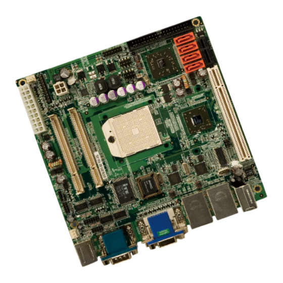
KINO-690S1 Mini-ITX Motherboard 1.1 Overview The KINO-690S1 Mini-ITX form factor CPU card is an AMD Socket S1 processor platform. Up to 4GB of DDR2 SO-DIMM SDRAM and up to four SATA II hard disk drives (HDD) are supported. SATA drives can be installed in a RAID configuration. High-performance PCI Express (PCIe) Gigabit Ethernet (GbE) connectivity is integrated into the system. -
Page 21: Figure 1-1: Kino-690S1 Overview [Front View]
KINO-690S1 Mini-ITX Motherboard Figure 1-1: KINO-690S1 Overview [Front View] Figure 1-2 shows the external peripheral interface connectors (EPIC). Figure 1-2: External Peripheral Interface Connectors Page 3... -
Page 22: Kino-690S1 Peripheral Connectors And Jumpers
1 x TPM connector 1 x TV Out connector 2 x USB 2.0 connectors (support four USB 2.0 devices) The KINO-690S1 has the following external peripheral interface connectors on the board rear panel. 2 x Audio Jacks 2 x Ethernet connectors... -
Page 23: Technical Specifications
KINO-690S1 Mini-ITX Motherboard 1.2.3 Technical Specifications KINO-690S1 technical specifications are listed in Table 1-1. See Chapter 2 for details. Specification KINO-690S1 Form Factor Mini-ITX AMD Socket S1 Turion™ 64 X2 System CPU AMD Socket S1 Sempron™ HyperTransport™ Up to 1600 MHz HyperTransport™ interfaces supported... -
Page 24: Table 1-1: Technical Specifications
KINO-690S1 Mini-ITX Motherboard Eight USB 2.0 devices supported USB2.0 One 40-pin IDE connector connects to two Ultra ATA33/66/100/133 devices Four 3.0Gb/s SATA II drives supported SATA Keyboard/mouse Two PS/2 connectors One PCI slot Expansion One PCIe x1 slot One 8-bit digital input/output connector; 4-bit input/4-bit... -
Page 25: Detailed Specifications
KINO-690S1 Mini-ITX Motherboard Chapter Detailed Specifications Page 7... -
Page 26: Dimensions
KINO-690S1 Mini-ITX Motherboard 2.1 Dimensions 2.1.1 Board Dimensions The dimensions of the board are listed below: Length: 170mm Width: 170mm Figure 2-1: KINO-690S1 Dimensions (mm) Page 8... -
Page 27: External Interface Panel Dimensions
KINO-690S1 Mini-ITX Motherboard 2.1.2 External Interface Panel Dimensions External peripheral interface connector panel dimensions are shown in Figure 2-2. Figure 2-2: External Interface Panel Dimensions (mm) 2.2 Data Flow Figure 2-3 shows the data flow between the two on-board chipsets and other components installed on the motherboard and described in the following sections of this chapter. -
Page 28: Figure 2-3: Data Flow Block Diagram
KINO-690S1 Mini-ITX Motherboard Figure 2-3: Data Flow Block Diagram Page 10... -
Page 29: Compatible Processors
AMD Turion™ 64 X2 dual-core mobile processor Mobile AMD Sempron™ processor 2.3.2 DDR2 Memory Controller All processors supported by the KINO-690S1 CPU card have their own DDR2 memory controller. The DDR2 controller has the following features: Low-latency, high-bandwidth 667MHz 128-bit DDR2 SDRAM controller... -
Page 30: Processor Electrical Interfaces
The AMD 690G PCIe bus is compliant with the PCI Express 1.1a. Three of the four AMD 690G lanes are implemented on the KINO-690S1 motherboard. One of these lanes is interfaced to a PCIe x1 expansion slot. Two other PCIe x1 lanes are interfaced to two Broadcom PCIe GbE controllers. -
Page 31: Pcie Gbe Ethernet
KINO-690S1 Mini-ITX Motherboard Figure 2-5: PCIe x1 Expansion Slot 2.4.2 PCIe GbE Ethernet Two PCIe x1 lanes from the AMD 690G Northbridge are interfaced to two Broadcom BCM5787M PCIe GbE controllers shown in Figure 2-6 below. Page 13... -
Page 32: Acceleration Features
KINO-690S1 Mini-ITX Motherboard Figure 2-6: Broadcom PCI GbE Controllers The Broadcom BCM5787M is a 10/100/1000BASE-T Ethernet LAN controller. The BCM5787M combines a triple-speed IEEE 802.3 compliant Media Access Controller (MAC) with a triple-speed Ethernet transceiver, a PCIe bus interface, and an on-chip buffer memory. -
Page 33: Display Support
Supports top quality DVD and time-shifted SDTV/HDTV television playback with low CPU usage 2.4.4 Display Support The AMD 690G supports dual independent displays. The following display interface connectors are on the KINO-690S1: TV Out DVI-D 2.4.4.1 TV Out TV Out features include: Integrated TV encoder from Xilleon products with integrated Avivo™... -
Page 34: Multiple Display Features
KINO-690S1 Mini-ITX Motherboard 2.4.4.2 Multiple Display Features The Multiple display features include Dual independent displays including one digital outputs * Resolution, refresh rates, and display data can be completely independent for the two display paths Supports both interlaced and non-interlaced displays 2.4.4.3 DVI... -
Page 35: Pci Host Bus Controller
KINO-690S1 Mini-ITX Motherboard 2.5.3 PCI Host Bus Controller The PCI interface on the AMD SB600 Southbridge is compliant with the PCI Revision 2.3 implementation. Some of the features of the PCI interface are listed below. PCI rev. 2.3 specifications PCI bus at 33 MHz... -
Page 36: Usb Controllers
USB debug port Port disable with individual control Four of the eight USB ports are interfaced to two 8-pin headers on the KINO-690S1. Four more USB ports are interfaced to four external USB connectors. See Figure 2-8. Figure 2-8: USB Connectors... -
Page 37: Smbus Controller
KINO-690S1 Mini-ITX Motherboard 2.5.5 SMBus Controller The AMD SB600 southbridge chipset SMBus Controller is SMBus Rev. 2.0 compliant and supports SMBALERT # signal / GPIO. 2.5.6 Interrupt Controller The AMD SB600 southbridge interrupt controller supports the following: IOAPIC/X-IO APIC mode for 24 channels of interrupts... -
Page 38: Sata Ii Ahci Controller
2.5.9 SATA II AHCI Controller The integrated SATA controllers on the AMD SB600 Southbridge supports four SATA II drives on the KINO-690S1 with independent DMA operations. The SATA controller supports the following: Four SATA ports, complying with SATA 2.0 specifications SATA II 3.0GHz PHY, with backward compatibility with 1.5GHz... -
Page 39: Ide Controller
KINO-690S1 Mini-ITX Motherboard 2.5.10 IDE Controller The AMD SB600 Southbridge IDE controller is interfaced to a single IDE connector. The IDE controller has the following specifications. Single PATA channel support Support PIO, multi-word DMA, and Ultra DMA 33/66/100/133 modes 32x32 byte buffers on each channel for buffering... -
Page 40: Figure 2-11: Audio Codec And Audio Jacks
KINO-690S1 Mini-ITX Motherboard 6/8 channel support on audio codec Multiple functions for audio and modem Codec operations Bus master logic Supports up to 3 codecs simultaneously Supports SDIF output AC Link The AC Link Interface is connected to a 16-bit, full-duplex AC'97 Rev. 2.3 compatible six-channel RealTek ALC655 audio CODEC. -
Page 41: Timers
KINO-690S1 Mini-ITX Motherboard 12.288MHz BITCLK input Integrated PCBEEP generator to save buzzer Interrupt capability Three analog line-level stereo inputs with 5-bit volume control, LINE_IN, CD, High-quality differential CD input Two analog line-level mono inputs: PCBEEP, PHONE-IN Dedicated Front-MIC input for front panel applications (software selectable) Boost preamplifier for MIC input LINE input shared with surround output;... -
Page 42: Rtc (Real Time Clock)
KINO-690S1 Mini-ITX Motherboard 2.5.13 RTC (Real Time Clock) 256 bytes of battery backed RAM is provided by the real time clock (RTC) integrated into the AMD SB600. The RTC keeps track of the time and stores system data even when the system is turned off. -
Page 43: Lpc Bus Components
KINO-690S1 Mini-ITX Motherboard 2.6 LPC Bus Components 2.6.1 LPC Bus Overview The LPC bus is connected to components listed below: BIOS chipset Super I/O chipset Serial Port Chipset TPM module connector Figure 2-12: LPC BUS Components 2.6.2 BIOS Chipset: The BIOS chipset has a licensed copy of AMI BIOS installed on the chipset. Some of the... -
Page 44: Tpm Module
USB booting support 2.6.3 TPM Module A TPM connector on the KINO-690S1 is interfaced to the AMD SB600 southbridge through the LPC bus. The AMD SB600 Southbridge supports TPM version 1.1 and TPM version 1.2 devices for enhanced security. Three TPM are available from IEI. The three IEI... -
Page 45: Super I/O Lpc Interface
KINO-690S1 Mini-ITX Motherboard Single +5V Power Supply Some of the Super I/O features are described in more detail below: 2.6.4.1 Super I/O LPC Interface ® The LPC interface on the Super I/O complies with the AMD Low Pin Count Specification Rev. -
Page 46: Super I/O Infrared
ASKIR 2.6.5 Serial Port Chipset The KINO-690S1 has a Fintek F81216DG chipset onboard enables the addition of two additional UART serial ports (COM3 and COM4). UART includes 16-byte send/receive FIFO. The Fintek serial port chipset is interfaced to the southbridge chipset through the LPC bus. -
Page 47: Operating Temperature And Temperature Control
+1.20V +3.3V +5.0V 5VSB VBAT The KINO-690S1 Super I/O Enhanced Hardware Monitor also monitors the following fan speeds: CPU Fan speed System Fan speed The values for the above environmental parameters are all recorded in the BIOS Hardware Health Configuration menu. -
Page 48: Power Consumption
KINO-690S1 Mini-ITX Motherboard 2.7.3 Power Consumption Table 2-1 shows the power consumption parameters for the KINO-690S1 running with a AMD Mobile Sempron 3500+ CPU and a 512MB 667MHz DDR2 SO-DIMM. Voltage Current +5.0V 3.65A +12V 1.12A Table 2-1: Power Consumption... -
Page 49: Unpacking
KINO-690S1 Mini-ITX Motherboard Chapter Unpacking Page 31... -
Page 50: Anti-Static Precautions
When the KINO-690S1 is unpacked, please do the following: Follow the anti-static precautions outlined in Section 3.1. Make sure the packing box is facing upwards so the KINO-690S1 does not fall out of the box. Make sure all the components shown in Section 3.3 are present. -
Page 51: Unpacking Checklist
If some of the components listed in the checklist below are missing, please do not proceed with the installation. Contact the IEI reseller or vendor you purchased the KINO-690S1 from or contact an IEI sales representative directly. To contact an IEI sales representative, please send an email to sales@iei.com.tw. -
Page 52: Table 3-1: Package List Contents
KINO-690S1 Mini-ITX Motherboard Dual RS-232 cable (P/N: 19800-000051-RS) SATA cables (P/N: 32000-062800-RS) SATA power cables (P/N: 32100-088600-RS) Mini jumper Pack Quick Installation Guide Utility CD Table 3-1: Package List Contents Page 34... -
Page 53: Optional Items
KINO-690S1 Mini-ITX Motherboard 3.4 Optional Items CPU cooler (P/N: CF-479B-RS) HDTV Output Cable (P/N: 32000-083701-RS) Dual RS-232 cable (P/N: 32200-000077-RS) Dual USB cable (w bracket) (P/N:CB-USB02-RS) 4-port USB cable (P/N: CB-USB14-RS) Table 3-2: Package List Contents Page 35... - Page 54 KINO-690S1 Mini-ITX Motherboard Page 36...
-
Page 55: Connector Pinouts
KINO-690S1 Mini-ITX Motherboard Chapter Connector Pinouts Page 37... -
Page 56: Peripheral Interface Connectors
Figure 4-1 shows the on-board peripheral connectors, rear panel peripheral connectors and on-board jumpers. Figure 4-1: Connector and Jumper Locations 4.1.2 Peripheral Interface Connectors Table 4-1 shows a list of the peripheral interface connectors on the KINO-690S1. Detailed descriptions of these connectors can be found below. Page 38... -
Page 57: Table 4-1: Peripheral Interface Connectors
KINO-690S1 Mini-ITX Motherboard Connector Type Label Audio connector 10-pin header FPAUDIO1 ATX power connector 20-pin ATX PWR1 Cooling fan connector, CPU 3-pin header CPU_FAN1 Cooling fan connector, System 3-pin header CPU_SYS1 Digital input/output connector 10-pin header DIO1 Front panel connector... -
Page 58: External Interface Panel Connectors
KINO-690S1 Mini-ITX Motherboard 4.1.3 External Interface Panel Connectors Table 4-2 lists the rear panel connectors on the KINO-690S1. Detailed descriptions of these connectors can be found in Section 4.3 on page 60. Connector Type Label DVI and VGA combo connector... -
Page 59: Digital Input/Output (Dio) Connector
KINO-690S1 Mini-ITX Motherboard Figure 4-2: ATX Power Connector Pinout Locations PIN NO. DESCRIPTION PIN NO. DESCRIPTION +3.3V +3.3V +3.3V -12V PS-ON PW-OK +VCC5SB +12V Table 4-3: ATX Power Connector Pinouts 4.2.2 Digital Input/Output (DIO) Connector CN Label: DIO1 CN Type:... -
Page 60: Fan Connector (+12V)
KINO-690S1 Mini-ITX Motherboard The digital input/output connector is managed through a Super I/O chip. The DIO connector pins are user programmable. Figure 4-3: DIO Connector Connector Locations PIN NO. DESCRIPTION PIN NO. DESCRIPTION Output 3 Output 2 Output 1 Output 0... -
Page 61: Front Panel Connector (14-Pin)
KINO-690S1 Mini-ITX Motherboard system BIOS can recognize the fan speed. Please note that only specified fans can issue the rotation signals. Figure 4-4: +12V Fan Connector Location PIN NO. DESCRIPTION GND Rotation Signal +12V Table 4-5: +12V Fan Connector Pinouts 4.2.4 Front Panel Connector (14-pin) -
Page 62: Figure 4-5: Front Panel Connector Pinout Locations (14-Pin)
KINO-690S1 Mini-ITX Motherboard Speaker Power button Reset HDD LED Figure 4-5: Front Panel Connector Pinout Locations (14-pin) FUNCTION DESCRIPTION FUNCTION DESCRIPTION Power LED+ Speaker SPEAKER+ BLINK Power PWRBTSW+ SPEAKER - Button Reset HDD LED IDE LED+ RESET+ IDE LED- Table 4-6: Front Panel Connector Pinouts (14-pin) -
Page 63: Ide Connector (40-Pin)
CN Type: 40-pin header (2x20) CN Location: See Figure 4-6 CN Pinouts: See Table 4-7 One 40-pin IDE device connector on the KINO-690S1 supports connectivity to two hard disk drives. Figure 4-6: IDE Device Connector Locations PIN NO. DESCRIPTION PIN NO. -
Page 64: Infrared Interface Connector (5-Pin)
KINO-690S1 Mini-ITX Motherboard GROUND IDE DRQ GROUND IOW# GROUND IOR# GROUND IDE CHRDY GROUND IDE DACK GROUND–DEFAULT INTERRUPT HDC CS0# HDC CS1# HDD ACTIVE# GROUND Table 4-7: IDE Connector Pinouts 4.2.6 Infrared Interface Connector (5-pin) CN Label: 5-pin header (1x5) -
Page 65: Pci Slot
KINO-690S1 Mini-ITX Motherboard Figure 4-7: Infrared Connector Pinout Locations PIN NO. DESCRIPTION IR-RX IR-TX Table 4-8: Infrared Connector Pinouts 4.2.7 PCI Slot CN Label: PCI1 CN Type: PCI Slot CN Location: See Figure 4-8 CN Pinouts: See Table 4-9 The PCI slot enables a PCI expansion module to be connected to the board. - Page 66 KINO-690S1 Mini-ITX Motherboard Page 48...
-
Page 67: Figure 4-8: Pci Slot Location
KINO-690S1 Mini-ITX Motherboard Figure 4-8: PCI Slot Location Page 49... - Page 68 KINO-690S1 Mini-ITX Motherboard PIN NO. DESCRIPTION PIN NO. DESCRIPTION TRST -12V +12V INTA INTC INTB INTD RESERVED3 PRSNT1 RESERVED1 RESERVED4 PRSNT2 3.3V_AUX RESERVED2 AD30 AD31 +3.3V AD29 AD28 AD26 AD27 AD25 AD24 +3.3V IDSEL C/BE3 +3.3V AD23 AD22 AD20 AD21...
-
Page 69: Table 4-9: Pci Slot
KINO-690S1 Mini-ITX Motherboard AD16 AD17 +3.3V C/BE2 FRAME IRDY TRDY +3.3V DEVSEL STOP +3.3V LOCK SDONE PERR +3.3V SERR +3.3V AD15 C/BE1 +3.3V AD14 AD13 AD11 AD12 AD10 C/BE0 +3.3V +3.3V REQ64 ACK64 Table 4-9: PCI Slot Page 51... -
Page 70: Pci Express X1 Slot
KINO-690S1 Mini-ITX Motherboard 4.2.8 PCI Express x1 Slot CN Label: PCIE_2, PCIE_3 CN Type: 10-pin header (2x5) CN Location: See Figure 4-9 CN Pinouts: See Table 4-10 PCIe x1 expansion devices can be inserted into the PCIe x1 slots. Page 52... -
Page 71: Figure 4-9: Pci Express X1 Slot Locations
KINO-690S1 Mini-ITX Motherboard Figure 4-9: PCI Express x1 Slot Locations PIN NO. DESCRIPTION PIN NO. DESCRIPTION +12v +12v +12v +12v +12v SCLOCK SDATA +3.3v +3.3v +3.3v +3.3v Dual PCIE RST PCIE WAKEUP PCIE CLOCK+ PCIE CLOCK- GPP_TX3P Page 53... -
Page 72: Sata Drive Connectors
KINO-690S1 Mini-ITX Motherboard GPP_TX3N GPP_RX3P GPP_RX3N Table 4-10: PCI Express x1 Slot Pinouts 4.2.9 SATA Drive Connectors CN Label: SATA1, SATA2, SATA3, and SATA4 CN Type: 7-pin SATA drive connectors See Figure 4-10 CN Location: CN Pinouts: See Table 4-11 The two SATA drive connectors are each connected to a first generation SATA drive. -
Page 73: Serial Port Connector (Com3)
KINO-690S1 Mini-ITX Motherboard PIN NO. DESCRIPTION Table 4-11: SATA Drive Connector Pinouts 4.2.10 Serial Port Connector (COM3) COM3 CN Label: CN Type: 10-pin header (2x5) CN Location: See Figure 4-11 CN Pinouts: See Table 4-12 The 10-pin serial port connector provides a second RS-232 serial communications channel. -
Page 74: Serial Port Connector (Com4)(Rs-232, Rs-422 Or Rs-485)
KINO-690S1 Mini-ITX Motherboard Receive Data (RXD) Request To Send (RTS) Transmit Data (TXD) Clear To Send (CTS) Data Terminal Ready (DTR) Ring Indicator (RI) Ground (GND) Ground (GND) Table 4-12: Serial Connector Pinouts 4.2.11 Serial Port Connector (COM4)(RS-232, RS-422 or RS-485) -
Page 75: Trusted Platform Module (Tpm) Connector
KINO-690S1 Mini-ITX Motherboard PIN NO. DESCRIPTION PIN NO. DESCRIPTION NDSR2 NRTS2 NCTS2 NRI2 TXD85+ TXD485# RXD85+ RXD485# Table 4-13: RS-232/RS-485 Serial Port Connector Pinouts 4.2.12 Trusted Platform Module (TPM) Connector CN Label: TPM1 40-pin header (2x20) CN Type: CN Location:... -
Page 76: Tv Out Connector
KINO-690S1 Mini-ITX Motherboard PIN NO. DESCRIPTION PIN NO. DESCRIPTION LCLK GND2 LFRAME# LRESET# LAD3 LAD2 LAD1 LAD0 GND3 SB3V SERIRQ GND1 GLKRUN# LPCPD# LDRQ# Table 4-14: TPM Connector Pinouts 4.2.13 TV Out Connector CN Label: 6-pin header (2x3) CN Type:... -
Page 77: Usb Connectors (Internal)
KINO-690S1 Mini-ITX Motherboard S-Video Connector PIN NO. DESCRIPTION PIN NO. DESCRIPTION Luminance (Y) Chrominance (Pr) Chrominance (Pb) Table 4-15: TV Port Connector Pinouts 4.2.14 USB Connectors (Internal) CN Label: JUSB1 and JUSB2 CN Type: 8-pin header (2x4) CN Location: See Figure 4-15... -
Page 78: External Peripheral Interface Connector Panel
DATAM- Table 4-16: USB Port Connector Pinouts 4.3 External Peripheral Interface Connector Panel Figure 4-16 shows the KINO-690S1 external peripheral interface connector (EPIC) panel. The KINO-690S1 EPIC panel consists of the following: 3 x Audio jack connectors 1 x DVI connector... -
Page 79: Dvi And Vga Combo Connector
KINO-690S1 Mini-ITX Motherboard See Figure 4-16 CN Location: The three audio jacks on the external audio connector enable the KINO-690S1 to be connected to external audio devices as specified below. Line Out port (Lime): Connects to a headphone or a speaker. With multi-channel configurations, this port can also connect to front speakers. -
Page 80: Figure 4-18: Dvi-D Connector Pinouts
KINO-690S1 Mini-ITX Motherboard Figure 4-18: DVI-D Connector Pinouts Signal Name Pin # Signal Name Pin # Signal Name TMDS Data2- TMDS Data1- TMDS Data0- TMDS Data2+ TMDS Data1+ TMDS Data0+ DDC Clock [SCL] PVDD1 DDC Data [SDA] TMDS Clock +... -
Page 81: Keyboard/Mouse Connector
DDC DAT HSYNC VSYNC DDCCLK Table 4-18: VGA Connector Pinouts 4.3.3 Keyboard/Mouse Connector CN Label: CN Type: Dual PS/2 CN Location: See Figure 4-16 CN Pinouts: See Figure 4-20 The KINO-690S1 keyboard and mouse connectors are standard PS/2 connectors. Page 63... -
Page 82: Lan Connectors
KINO-690S1 Mini-ITX Motherboard Figure 4-20: PS/2 Pinouts DESCRIPTION DESCRIPTION L_KDAT L_MDAT L_KCLK L_MCLK Table 4-19: PS/2 Connector Pinouts 4.3.4 LAN Connectors CN Label: J20 and J21 CN Type: RJ-45 Page 64... -
Page 83: Figure 4-21: Rj-45 Ethernet Connector
CN Pinouts: See Table 4-20 The KINO-690S1 is equipped with two built-in RJ-45 Ethernet controllers. The controllers can connect to the LAN through two RJ-45 LAN connectors. There are two LEDs on the connector indicating the status of LAN. The pin assignments are listed in the following... -
Page 84: Serial Port Connectors (Com1 And Com2 )
KINO-690S1 Mini-ITX Motherboard 4.3.5 Serial Port Connectors (COM1 and COM2 ) CN Label: COM1 and COM2 CN Type: DB-9 connectors CN Location: See Figure 4-16 (see 2) CN Pinouts: See Table 4-22 and Figure 4-22 Two serial port connectors, COM1 and COM2, are externally accessible. The 9-pin DB-9 serial port connectors are connected to RS-232 serial communications devices. -
Page 85: Table 4-23: Usb Port Pinouts
KINO-690S1 Mini-ITX Motherboard See Table 4-23 CN Pinouts: The KINO-690S1 has four external USB 2.0 ports. The ports are integrated into two dual USB and LAN combo connectors. The USB ports connect to both USB 2.0 and USB 1.1 devices. -
Page 86: Installation
KINO-690S1 Mini-ITX Motherboard Chapter Installation Page 68... -
Page 87: Anti-Static Precautions
Electrostatic discharge (ESD) can cause serious damage to electronic components, including the KINO-690S1. Dry climates are especially susceptible to ESD. It is therefore critical that whenever the KINO-690S1, or any other electrical component is handled, the following anti-static precautions are strictly adhered to. -
Page 88: Installation Considerations
KINO-690S1 is installed. All installation notices pertaining to the installation of the KINO-690S1 should be strictly adhered to. Failing to adhere to these precautions may lead to severe damage of the KINO-690S1 and injury to the person installing the motherboard. 5.2.1 Installation Notices... -
Page 89: Installation Checklist
Allow screws to come in contact with the PCB circuit, connector pins, or its components. 5.2.2 Installation Checklist The following checklist is provided to ensure the KINO-690S1 is properly installed. All the items in the packing list are present The CPU is installed... -
Page 90: Unpacking
When the KINO-690S1 is unpacked, please do the following: Follow the anti-static precautions outlined in Section 5.1. Make sure the packing box is facing upwards so the KINO-690S1 does not fall out of the box. Make sure all the components in the checklist shown in Chapter 3 are present. -
Page 91: Cpu, Cpu Cooling Kit And Dimm Installation
To install a AMD Socket S1 CPU onto the KINO-690S1, follow the steps below: WARNING: When handling the CPU, only hold it on the sides. DO NOT touch the pins at the bottom of the CPU. -
Page 92: Figure 5-1: Make Sure The Cpu Socket Retention Screw Is Unlocked
KINO-690S1 Mini-ITX Motherboard Step 1: Unlock the CPU retention screw. When shipped, the retention screw of the CPU socket should be in the unlocked position. If it is not in the unlocked position, use a screwdriver to unlock the screw. See Figure 5-1. -
Page 93: Cooling Kit Cf-479B-Rs Installation
KINO-690S1 Mini-ITX Motherboard Step 7: Lock the retention screw. Rotate the retention screw into the locked position. Step 0: 5.4.2 Cooling Kit CF-479B-RS Installation Figure 5-2: IEI CF-479B-RS Cooling Kit An IEI AMD Socket S1 CPU cooling kit (Figure 5-2) can be purchased separately. The cooling kit comprises a CPU heat sink and a cooling fan. -
Page 94: Figure 5-3: Cooling Kit Support Bracket
KINO-690S1 Mini-ITX Motherboard holes. (See Figure 5-3) Figure 5-3: Cooling Kit Support Bracket Step 4: Tighten the screws. Use a screwdriver to tighten the four screws. Tighten each nut a few turns at a time and do not over-tighten the screws. -
Page 95: So-Dimm Installation
Figure 5-5. Figure 5-5: SO-DIMM Installation Step 1: Locate the SO-DIMM socket. Place the KINO-690S1 on an anti-static pad with the solder side facing up. Step 2: Align the SO-DIMM with the socket. The SO-DIMM must be oriented in such a way that the notch in the middle of the SO-DIMM must be aligned with the plastic bridge in the socket. -
Page 96: Jumper Settings
OPEN a jumper means removing the plastic clip from a jumper. Before the KINO-690S1 is installed in the system, the jumpers must be set in accordance with the desired configuration. The jumpers on the KINO-690S1 are listed in Table 5-1. Description... -
Page 97: Clear Cmos Jumper
Jumper Location: See Figure 5-6 If the KINO-690S1 fails to boot due to improper BIOS settings, the clear CMOS jumper clears the CMOS data and resets the system BIOS information. To do this, use the jumper cap to close pins 2 and 3 for a few seconds then reinstall the jumper clip back to pins 1 and 2. -
Page 98: Com 4 Function Select Jumper
KINO-690S1 Mini-ITX Motherboard Figure 5-6: Clear CMOS Jumper 5.5.2 COM 4 Function Select Jumper Jumper Label: Jumper Type: 3-pin header Jumper Settings: See Table 5-3 Jumper Location: See Figure 5-7 The COM4 Function Select jumper sets the communication protocol used by the second serial communications port (COM4) as RS-232, RS-422 or RS-485. -
Page 99: Chassis Installation
The KINO-690S1 must be installed in a chassis with ventilation holes on the sides allowing airflow to travel through the heat sink surface. In a system with an individual power supply unit, the cooling fan of a power supply can also help generate airflow through the board surface. -
Page 100: Motherboard Installation
IEI website (http://www.ieiworld.com.tw) to find out more about the available chassis. 5.6.2 Motherboard Installation To install the KINO-690S1 motherboard into the chassis please refer to the reference material that came with the chassis. 5.7 Internal Peripheral Device Connections 5.7.1 Peripheral Device Cables... -
Page 101: Ata Flat Cable Connection
5.7.2 ATA Flat Cable Connection The ATA 66/100 flat cable connects to the KINO-690S1 to one or two IDE devices. To connect an IDE HDD to the KINO-690S1 please follow the instructions below. -
Page 102: Dual Rs-232 Cable Connection
KINO-690S1 Mini-ITX Motherboard side of the cable to one or two IDE devices. Make sure that pin 1 on the cable corresponds to pin 1 on the connectorStep 0: 5.7.3 Dual RS-232 Cable Connection The dual RS-232 cable consists of two connectors attached to two independent cables. -
Page 103: Sata Drive Connection
0: 5.7.4 SATA Drive Connection The KINO-690S1 is shipped with two SATA drive cables and one SATA drive power cable. To connect the SATA drives to the connectors, please follow the steps below. -
Page 104: Usb Cable (Dual Port)
SATA drive. See Figure 5-11. Step 0: Figure 5-11: SATA Power Drive Connection 5.7.5 USB Cable (Dual Port) The KINO-690S1 is shipped with a dual port USB 2.0 cable. To connect the USB cable connector, please follow the steps below. Step 1: Locate the connectors. -
Page 105: Usb Cable (Four Port)
If the USB pins are not properly aligned, the USB device can burn out. Step 2: Align the connectors. Each cable has two connectors. Correctly align pin 1on each cable connector with pin 1 on the KINO-690S1 USB connectors. Page 87... -
Page 106: External Peripheral Interface Connection
KINO-690S1 Mini-ITX Motherboard Step 3: Insert the cable connectors. Once the cable connectors are properly aligned with the USB connectors on the KINO-690S1, connect the cable connectors to the onboard connectors. See Figure 5-13. Figure 5-13: Four Port USB Cable Connection Step 4: Attach the bracket to the chassis. -
Page 107: Audio Connection
Figure 5-14: Audio Connectors 5.8.2 DVI Display Device Connection The KINO-690S1 has a single female DVI connector on the external peripheral interface panel. The DVI connector is connected to a digital display device. To connect a digital display device to the KINO-690S1, please follow the instructions below. -
Page 108: Lan Connection (Single Connector)
Once the connectors are properly aligned with the male connector, insert the male connector from the digital display device into the female connector on the KINO-690S1. See Figure 5-15. Figure 5-15: DVI Connector Step 4: Secure the connector. Secure the DVI connector from the digital display device to the external interface by tightening the two retention screws on either side of the connector. -
Page 109: Ps/2 Keyboard And Mouse Connection
Step 0: 5.8.4 PS/2 Keyboard and Mouse Connection The KINO-690S1 has a dual PS/2 connector on the external peripheral interface panel. The dual PS/2 connector is used to connect to a keyboard and mouse to the system. Follow the steps below to connect a keyboard and mouse to the KINO-690S1. -
Page 110: Serial Device Connection
Step 0: Figure 5-17: PS/2 Keyboard/Mouse Connector 5.8.5 Serial Device Connection The KINO-690S1 has a single female DB-9 connector on the external peripheral interface panel for a serial device. Follow the steps below to connect a serial device to the KINO-690S1. -
Page 111: Usb Connection (Dual Connector)
KINO-690S1 Mini-ITX Motherboard Figure 5-18: Serial Device Connector Step 3: Secure the connector. Secure the serial device connector to the external interface by tightening the two retention screws on either side of the connector. Step 0: 5.8.6 USB Connection (Dual Connector) The external USB Series "A"... -
Page 112: Vga Monitor Connection
Figure 5-19: USB Connector 5.8.7 VGA Monitor Connection The KINO-690S1 has a single female DB-15 connector on the external peripheral interface panel. The DB-15 connector is connected to a CRT or VGA monitor. To connect a monitor to the KINO-690S1, please follow the instructions below. -
Page 113: Figure 5-20: Vga Connector
KINO-690S1 Mini-ITX Motherboard Figure 5-20: VGA Connector Step 4: Secure the connector. Secure the DB-15 VGA connector from the VGA monitor to the external interface by tightening the two retention screws on either side of the connector. Step 0: Page 95... -
Page 114: Bios Screens
KINO-690S1 Mini-ITX Motherboard Chapter BIOS Screens Page 96... -
Page 115: Introduction
KINO-690S1 Mini-ITX Motherboard 6.1 Introduction A licensed copy of AMI BIOS is preprogrammed into the ROM BIOS. The BIOS setup program allows users to modify the basic system configuration. This chapter describes how to access the BIOS setup program and the configuration options that may be changed. -
Page 116: Getting Help
KINO-690S1 Mini-ITX Motherboard F1 key General help, only for Status Page Setup Menu and Option Page Setup Menu F2 /F3 key Change color from total 16 colors. F2 to select color forward. F10 key Save all the CMOS changes, only for Main Menu Table 6-1: BIOS Navigation Keys 6.1.3 Getting Help... -
Page 117: Main
KINO-690S1 Mini-ITX Motherboard 6.2 Main The Main BIOS menu (BIOS Menu 1) appears when the BIOS Setup program is entered. The Main menu gives an overview of the basic system information. BIOS Menu 1: Main System Overview The System Overview lists a brief summary of different system components. The fields in System Overview cannot be changed. -
Page 118: Advanced
KINO-690S1 Mini-ITX Motherboard Count: The number of CPUs on the motherboard System Memory: Displays the auto-detected system memory. Size: Lists memory size The System Overview field also has two user configurable fields: System Time [xx:xx:xx] Use the System Time option to set the system time. Manually enter the hours, minutes and seconds. -
Page 119: Cpu Configuration
KINO-690S1 Mini-ITX Motherboard BIOS Menu 2: Advanced 6.3.1 CPU Configuration Use the CPU Configuration menu (BIOS Menu 3) to view detailed CPU specifications and configure the CPU. Page 101... -
Page 120: Ide Configuration
KINO-690S1 Mini-ITX Motherboard BIOS Menu 3: CPU Configuration The CPU Configuration menu (BIOS Menu 3) lists the following CPU details: Revision: Lists the CPU revision number Cache L1: Lists the CPU L1 cache size Cache L2: Lists the CPU L2 cache size... -
Page 121: Onboard Pci Ide Controller [Both]
KINO-690S1 Mini-ITX Motherboard BIOS Menu 4: IDE Configuration OnBoard PCI IDE Controller [Both] The OnBoard PCI IDE Controller BIOS option specifies the IDE channels used by the onboard PCI IDE controller. The following configuration options are available. Disabled Prevents the system from using the onboard IDE... -
Page 122: Ide Master, Ide Slave
KINO-690S1 Mini-ITX Motherboard When entering setup, BIOS auto detects the presence of IDE devices. BIOS displays the status of the auto detected IDE devices. The following IDE devices are detected and are shown in the IDE Configuration menu: Primary IDE Master... -
Page 123: Auto-Detected Drive Parameters
KINO-690S1 Mini-ITX Motherboard BIOS Menu 5: IDE Master and IDE Slave Configuration Auto-Detected Drive Parameters The “grayed-out” items in the left frame are IDE disk drive parameters automatically detected from the firmware of the selected IDE disk drive. The drive parameters are listed as follows: Device: Lists the device type (e.g. -
Page 124: Type [Auto]
KINO-690S1 Mini-ITX Motherboard interrupt if block mode is not used. Block mode allows transfers of up to 64 KB per interrupt. PIO Mode: Indicates the PIO mode of the installed device. Async DMA: Indicates the highest Asynchronous DMA Mode that is supported. -
Page 125: Lba/Large Mode [Auto]
KINO-690S1 Mini-ITX Motherboard LBA/Large Mode [Auto] Use the LBA/Large Mode option to disable or enable BIOS to auto detects LBA (Logical Block Addressing). LBA is a method of addressing data on a disk drive. In LBA mode, the maximum drive capacity is 137 GB. -
Page 126: Dma Mode [Auto]
KINO-690S1 Mini-ITX Motherboard PIO mode 0 selected with a maximum transfer rate of 3.3MBps PIO mode 1 selected with a maximum transfer rate of 5.2MBps PIO mode 2 selected with a maximum transfer rate of 8.3MBps PIO mode 3 selected with a maximum transfer rate of 11.1MBps PIO mode 4 selected with a maximum transfer rate of 16.6MBps... -
Page 127: Auto]
KINO-690S1 Mini-ITX Motherboard UDMA1 Ultra DMA mode 0 selected with a maximum data transfer rate of 16.6MBps Ultra DMA mode 1 selected with a maximum data transfer UDMA1 rate of 25MBps UDMA2 Ultra DMA mode 2 selected with a maximum data transfer rate of 33.3MBps... -
Page 128: Super Io Configuration
KINO-690S1 Mini-ITX Motherboard Disabled Prevents the BIOS from using 32-bit data transfers. Enabled Allows BIOS to use 32-bit data transfers on supported EFAULT hard disk drives. 6.3.3 Super IO Configuration Use the Super IO Configuration menu (BIOS Menu 6) to set or change the configurations for the FDD controllers, parallel ports and serial ports. -
Page 129: Serial Port1 Mode [Normal]
KINO-690S1 Mini-ITX Motherboard address is IRQ4 3E8/IRQ4 Serial Port 1 I/O port address is 3E8 and the interrupt address is IRQ4 2E8/IRQ3 Serial Port 1 I/O port address is 2E8 and the interrupt address is IRQ3 Serial Port1 Mode [Normal] Use the Serial Port1 Mode option to select the transmitting and receiving mode for the first serial port. -
Page 130: Serial Port3 Address [3E8]
KINO-690S1 Mini-ITX Motherboard Normal Serial Port 2 mode is normal EFAULT IrDA Serial Port 2 mode is IrDA ASK IR Serial Port 2 mode is ASK IR Serial Port3 Address [3E8] Use the Serial Port3 Address option to select the base addresses for serial port 3... -
Page 131: Hardware Health Configuration
KINO-690S1 Mini-ITX Motherboard Serial port 3 I/O port address is 338 Serial port 3 I/O port address is 238 6.3.4 Hardware Health Configuration The Hardware Health Configuration menu (BIOS Menu 7) shows the operating temperature, fan speeds and system voltages. -
Page 132: Acpi Configuration
KINO-690S1 Mini-ITX Motherboard System Fan Speed Voltages: The following system voltages are monitored CPU Core +1.20V +3.30V +5.0V 5VSB VBAT 6.3.5 ACPI Configuration The ACPI Configuration menu (BIOS Menu 8) configures the Advanced Configuration and Power Interface (ACPI) and Power Management (APM) options. -
Page 133: Trusted Computing
KINO-690S1 Mini-ITX Motherboard Use the ACPI Version Features option to select the ACPI (Advanced Configuration and Power Interface Specification) version to run on the system. ACPI v1.0 (Default) ACPI revision 1.0 runs on the system ACPI v2.0 ACPI revision 1.0 runs on the system ACPI v3.0... -
Page 134: Tcg/Tpm Support [Yes]
KINO-690S1 Mini-ITX Motherboard BIOS Menu 9: Trusted Computing TCG/TPM Support [Yes] Use the TCG/TPM Support option to configure support for the TPM. TPM support is disabled. EFAULT TPM support is enabled. TPM Enable/Disable Status [No State] Use the TPM Enable/Disable Status to see if the TPM module has been enabled or disabled. -
Page 135: Remote Access Configuration
KINO-690S1 Mini-ITX Motherboard 6.3.7 Remote Access Configuration Use the Remote Access Configuration menu (BIOS Menu 10) to configure remote access parameters. The Remote Access Configuration is an AMIBIOS feature and allows a remote host running a terminal program to display and configure the BIOS settings. -
Page 136: Serial Port Mode
KINO-690S1 Mini-ITX Motherboard Serial Port Mode Flow Control Redirection after BIOS POST Terminal Type VT-UTF8 Combo Key Support Sredir Memory Display Delay These configuration options are discussed below. Serial Port Number [COM1] Use the Serial Port Number option allows to select the serial port used for remote access. -
Page 137: Flow Control [None]
KINO-690S1 Mini-ITX Motherboard 19200 8,n,1 09600 8,n,1 NOTE: Identical baud rate setting musts be set on the host (a management computer running a terminal software) and the slave Flow Control [None] Use the Flow Control option to report the flow control method for the console redirection application. -
Page 138: Usb Configuration
KINO-690S1 Mini-ITX Motherboard ANSI The target terminal type is ANSI EFAULT VT100 The target terminal type is VT100 VT-UTF8 The target terminal type is VT-UTF8 VT-UTF8 Combo Key Support [Disabled] Use the VT-UFT8 Combo Key Support option to enable additional keys that are not provided by VT100 for the PC 101 keyboard. -
Page 139: Usb 1.1 Ehci Controller [Enabled]
KINO-690S1 Mini-ITX Motherboard BIOS Menu 11: USB Configuration USB 1.1 EHCI Controller [Enabled] The USB 1.1 OHCI Controller BIOS option enables or disables the USB 1.1 controller Disabled USB 1.1 function disabled Enabled (Default) USB 1.1 function enabled USB 2.0 EHCI Controller [Enabled] The USB 2.0 EHCI Controller BIOS option enables or disables the USB 2.0 controller... -
Page 140: Usb Mass Storage Device Configuration
KINO-690S1 Mini-ITX Motherboard Legacy USB Support [Enabled] Use the Legacy USB Support BIOS option to enable USB mouse and USB keyboard support. Normally if this option is not enabled, any attached USB mouse or USB keyboard does not become available until a USB compatible operating system is fully booted with all USB drivers loaded. -
Page 141: Usb Mass Storage Reset Delay [20 Sec]
KINO-690S1 Mini-ITX Motherboard BIOS Menu 12: USB Mass Storage Device Configuration USB Mass Storage Reset Delay [20 Sec] Use the USB Mass Storage Reset Delay option to set the number of seconds POST waits for the USB mass storage device after the start unit command. -
Page 142: Device
KINO-690S1 Mini-ITX Motherboard 40 Sec POST waits 40 seconds for the USB mass storage device after the start unit command. Device ## The Device## field lists the USB devices that are connected to the system. Emulation Type [Auto] Use the Emulation Type BIOS option to specify the type of emulation BIOS has to provide for the USB device. -
Page 143: Pci/Pnp
KINO-690S1 Mini-ITX Motherboard Hard Disk Allows the USB device to be emulated as hard disk responding to INT13h calls that return DL values of 80h or above. CDROM Assumes the CD-ROM is formatted as bootable media. All the devices that support block sizes greater than 512 bytes can only be booted using this option. -
Page 144: Menu 13: Pci/Pnp Configuration
KINO-690S1 Mini-ITX Motherboard BIOS Menu 13: PCI/PnP Configuration Page 126... -
Page 145: Clear Nvram [No]
KINO-690S1 Mini-ITX Motherboard Clear NVRAM [No] Use the Clear NVRAM option to specify if the NVRAM (Non-Volatile RAM) is cleared when the power is turned off. System does not clear NVRAM during system boot EFAULT System clears NVRAM during system boot Plug &... -
Page 146: Allocate Irq To Pci Vga [Yes]
KINO-690S1 Mini-ITX Motherboard Allocate IRQ to PCI VGA [Yes] Use the Allocate IRQ to PCI VGA option to restrict the system from giving the VGA adapter card an interrupt address. (Default) Assigns an IRQ to a PCI VGA card if card requests IRQ... -
Page 147: Offboard Pci/Isa Ide Card [Auto]
KINO-690S1 Mini-ITX Motherboard OffBoard PCI/ISA IDE Card [Auto] Use the OffBoard PCI/ISA IDE Card BIOS option to select the OffBoard PCI/ISA IDE Card. Auto The location of the Off Board PCI IDE adapter card is EFAULT automatically detected by the AMIBIOS. -
Page 148: Dma Channel# [Available]
KINO-690S1 Mini-ITX Motherboard Available The specified IRQ is available to be used by EFAULT PCI/PnP devices The specified IRQ is reserved for use by Legacy ISA Reserved devices Available IRQ addresses are: IRQ3 IRQ4 IRQ5 IRQ7 IRQ9 IRQ10 IRQ 11... -
Page 149: Boot
KINO-690S1 Mini-ITX Motherboard DM Channel 7 Reserved Memory Size [Disabled] Use the Reserved Memory Size BIOS option to specify the amount of memory that should be reserved for legacy ISA devices. No memory block reserved for legacy ISA devices Disabled... -
Page 150: Boot Settings Configuration
KINO-690S1 Mini-ITX Motherboard BIOS Menu 14: Boot 6.5.1 Boot Settings Configuration Use the Boot Settings Configuration menu (BIOS Menu 14) to configure advanced system boot options. Page 132... -
Page 151: Quick Boot [Enabled]
KINO-690S1 Mini-ITX Motherboard BIOS Menu 15: Boot Settings Configuration Quick Boot [Enabled] Use the Quick Boot BIOS option to make the computer speed up the boot process. Disabled No POST procedures are skipped Enabled Some POST procedures are skipped to decrease... -
Page 152: Boot Device Priority
KINO-690S1 Mini-ITX Motherboard Enabled OEM Logo displayed instead of POST messages PS/2 Mouse Support [Enabled] Use the PS/2 Mouse Support option adjusts PS/2 mouse support capabilities. Disabled PS/2 mouse support is disabled and prevented from using system resources. Enabled Allows the system to use a PS/2 mouse. -
Page 153: Hard Disk Drives
KINO-690S1 Mini-ITX Motherboard BIOS Menu 16: Boot Device Priority Settings 6.5.3 Hard Disk Drives Use the Hard Disk Drives menu to specify the boot sequence of the available HDDs. When the menu is opened, the HDDs connected to the system are listed as shown below:... -
Page 154: Menu 17: Hard Disk Drives
KINO-690S1 Mini-ITX Motherboard NOTE: Only the drives connected to the system are shown. For example, if only two HDDs are connected only “1st Drive” and “2nd Drive” are listed. The boot sequence from the available devices is selected. If the “1st Drive” option is selected a list of available HDDs is shown. -
Page 155: Cd/Dvd Drives
KINO-690S1 Mini-ITX Motherboard 6.5.4 CD/DVD Drives Use the CD/DVD Drives menu to specify the boot sequence of the available CD/DVD drives. When the menu is opened, the CD drives and DVD drives connected to the system are listed as shown below:... -
Page 156: Security
KINO-690S1 Mini-ITX Motherboard BIOS Menu 18: CD/DVD Drives 6.6 Security Use the Security menu (BIOS Menu 19) to set system and user passwords. Page 138... -
Page 157: Change Supervisor Password
KINO-690S1 Mini-ITX Motherboard BIOS Menu 19: Security Change Supervisor Password Use the Change Supervisor Password to set or change a supervisor password. The default for this option is Not Installed. If a supervisor password must be installed, select this field and enter the password. After the password has been added, Install appears next to Change Supervisor Password. -
Page 158: Chipset
KINO-690S1 Mini-ITX Motherboard Boot Sector Virus Protection [Disabled] Use the Boot Sector Virus Protection to enable the system to protect the computer boot sector from viruses. Disabled (Default) Disables the boot sector virus protection Enables the boot sector virus protection Enabled 6.7 Chipset... -
Page 159: Northbridge Chipset Configuration
KINO-690S1 Mini-ITX Motherboard BIOS Menu 20: Chipset 6.7.1 NorthBridge Chipset Configuration Use the NorthBridge Chipset Configuration menu (BIOS Menu 20) to check the northbridge chipset settings. Page 141... -
Page 160: Menu 21:Northbridge Chipset Configuration
KINO-690S1 Mini-ITX Motherboard BIOS Menu 21:NorthBridge Chipset Configuration The NorthBridge Chipset configuration menu has no configurable options. The NorthBridge Chipset configuration menu shows the following Northbridge chipset settings: Memory CLK: Shows the speed of the memory controller CAS (Latency): Specifies the Column Address Strobe (CAS) delay time... -
Page 161: Ecc Configuration
KINO-690S1 Mini-ITX Motherboard Row Cycle (Trc): Asynchronous Latency: 6.7.2 ECC Configuration Use the ECC Configuration menu (BIOS Menu 22) to set the ECC parameters. BIOS Menu 22: ECC Configuration Chipset Configuration DRAM ECC Enable [Enabled] Use the DRAM ECC Enable option to enable the hardware to report and correct memory errors and thereby automatically maintain the system. -
Page 162: Dram Scrub Redirect [Disabled]
KINO-690S1 Mini-ITX Motherboard Use the 4-Bit ECC Mode to enable or disable the 4-Bit ECC mode (a.k.a. CHIPKILL ECC MODE) Disabled 4-Bit ECC mode disabled Enabled (Default) 4-Bit ECC mode enabled DRAM SCRUB REDIRECT [Disabled] Use the DRAM SCRUB REDIRECT option to enable the system to immediately correct DRAM ECC errors when they occur, even when background scrubbing is on. -
Page 163: Internal Graphics Configuration
KINO-690S1 Mini-ITX Motherboard Use the L2 Cache BG Scrub option to enable the system to correct the L2 Data cache when idle. Disabled (Default) L2 cache can be corrected when the system is idle. Enabled L2 cache cannot be corrected when the system is idle. -
Page 164: Internal Graphics Mode [Uma]
KINO-690S1 Mini-ITX Motherboard BIOS Menu 23: Internal Graphics Configuration Internal Graphics Mode [UMA] Use the Internal Graphic Mode Select option to how the internal graphics accesses the memory. The internal graphics mode is disabled. Disabled SIDEPORT The integrated graphics core treats the SidePort memory... -
Page 165: Uma Buffer Size [Auto]
KINO-690S1 Mini-ITX Motherboard memory. UMA Buffer Size [Auto] Use the UMA Buffer Size option to specify the memory to be reserved for the integrated graphics. The following configuration options are available: Auto (Default) 32MB 64MB 128MB 256MB 512MB 1024MB Current UMA Buffer Size [Auto] The current UMA Buffer Size field specifies the amount of memory that is allocated to the integrated graphics. -
Page 166: Southbridge Configuration
KINO-690S1 Mini-ITX Motherboard PAL-N TV type is set to PAL-N Expansion Mode [Disabled] Use the Expansion Mode option to enable or disable the expansion mode. Disabled Expansion mode disabled EFAULT Expansion mode enabled Enabled 6.7.4 SouthBridge Configuration The SouthBridge Configuration menu (BIOS Menu 24) the southbridge chipset to be configured. -
Page 167: Ac97 Audio Device
KINO-690S1 Mini-ITX Motherboard BIOS Menu 24:SouthBridge Chipset Configuration AC97 Audio Device Use the AC97 Audio Device option to enable or disable the AC’97 CODEC. Disabled The onboard AC’97 is disabled Auto (Default) The onboard AC’97 automatically detected and enabled Set Spread Spectrum Function [Disabled] Use the Set Spread Spectrum BIOS option to improve CPU EMI issues. -
Page 168: Power
KINO-690S1 Mini-ITX Motherboard OnChip SATA [Enabled] Use the OnChip SATA option to enable or disable the SATA controller on the Southbridge. Disabled Disables the Southbridge SATA controller. Enables the Southbridge SATA controller. Enabled EFAULT OnChip SATA Type [Enabled] Use the OnChip SATA Type option to specify the drive type that is installed in the system/... -
Page 169: Power Management/Apm [Enabled]
KINO-690S1 Mini-ITX Motherboard BIOS Menu 25:Power Power Management/APM [Enabled] Use the Power Management/APM BIOS option to enable access to the advanced power management features. If this option is disabled, the only other option on the screen is the Power Button Mode. -
Page 170: Resume On Ring [Disabled]
KINO-690S1 Mini-ITX Motherboard On/Off (Default) When the power button is pressed the system is either turned on or off When the power button is pressed the system goes into Suspend suspend mode Resume on Ring [Disabled] Use the Resume on Ring option to enable the system to be roused from a suspended or standby state when there is activity on the RI (ring in) modem line. -
Page 171: Exit
KINO-690S1 Mini-ITX Motherboard Resume On RTC Alarm [Disabled] Use the Resume On RTC Alarm option to specify the time the system should be roused from a suspended state. Disabled (Default) The real time clock (RTC) cannot generate a wake event... -
Page 172: Save Changes And Exit
KINO-690S1 Mini-ITX Motherboard BIOS Menu 26:Exit Save Changes and Exit Use the Save Changes and Exit option to save the changes made to the BIOS options and to exit the BIOS configuration setup program. Discard Changes and Exit Use the Discard Changes and Exit option to exit the BIOS configuration setup program without saving the changes made to the system. -
Page 173: Load Optimal Defaults
KINO-690S1 Mini-ITX Motherboard Load Optimal Defaults Use the Load Optimal Defaults option to load the optimal default values for each of the parameters on the Setup menus. F9 key can be used for this operation. Load Failsafe Defaults Use the Load Failsafe Defaults option to load failsafe default values for each of the parameters on the Setup menus. -
Page 174: Software Drivers
KINO-690S1 Mini-ITX Motherboard Chapter Software Drivers Page 156... -
Page 175: Available Software Drivers
Audio driver Installation instructions are given below. 7.2 Driver CD Auto-run All the drivers for the KINO-690S1 are on the CD that came with the system. To install the drivers, please follow the steps below. Step 1: Insert the CD into a CD drive connected to the system. -
Page 176: Figure 7-1: Introduction Screen
KINO-690S1 Mini-ITX Motherboard Figure 7-1: Introduction Screen Step 3: Click KINO-690S1. Step 4: A new screen with a list of available drivers appears (Figure 7-2). Figure 7-2: Available Drivers Step 5: Select the driver to install from the list in Figure 7-2. Detailed driver installation instructions follow below. -
Page 177: Amd 690G Chipset Driver Installation
KINO-690S1 Mini-ITX Motherboard 7.3 AMD 690G Chipset Driver Installation To install the chipset driver, please follow the steps below. NOTE: The chipset driver control center requires Microsoft .NET Framework prior to installation. The driver control center is an application that allows a user to control the configuration of the AMD product. -
Page 178: Figure 7-4: Chipset Driver Installation Welcome Screen
KINO-690S1 Mini-ITX Motherboard Step 4: The screen in Figure 7-4 appears. Figure 7-4: Chipset Driver Installation Welcome Screen Step 5: Open the SB600 directory. The screen in Figure 7-5 appears. Figure 7-5: Chipset Driver Installation License Agreement Step 6: The screen in Figure 7-6 appears. Select the destination folder. -
Page 179: Figure 7-6: Select Destination Folder
KINO-690S1 Mini-ITX Motherboard Figure 7-6: Select Destination Folder Step 7: Click install to continue. Step 8: The screen in Figure 7-7 appears as the driver starts to install. Figure 7-7: Chipset Driver Installing Screen Step 9: The welcome screen shown in Figure 7-8 appears. -
Page 180: Figure 7-8: Welcome Screen
KINO-690S1 Mini-ITX Motherboard Figure 7-8: Welcome Screen Step 10: Click Y to continue. Step 11: The License agreement file in Figure 7-9 appears. Figure 7-9: Chipset Driver Readme File Information Step 12: Click Y to continue. Step 13: The screen in Figure 7-10 appears. -
Page 181: Figure 7-10: Chipset Driver Installation Complete
KINO-690S1 Mini-ITX Motherboard Figure 7-10: Chipset Driver Installation Complete Step 14: Select the installation type (Express or Custom) then click Next to continue. Step 15: The installer starts to load the display driver. Step 16: Next the WDM Capture drivers load (for VIVO or All-In-Wonder) Step 17: The Catalyst Control Center setup starts shortly after. -
Page 182: Broadcom Lan Driver (For Gbe Lan) Installation
KINO-690S1 Mini-ITX Motherboard Figure 7-11: Setup Complete Step 20: To complete the installation, click Finish. Step 0: 7.4 Broadcom LAN Driver (for GbE LAN) Installation To install the Broadcom LAN driver, please follow the steps below. Step 1: Open Windows Control Panel (Figure 7-12). -
Page 183: Figure 7-12: Windows Control Panel
KINO-690S1 Mini-ITX Motherboard Figure 7-12: Windows Control Panel Step 2: Double-click the System icon. Page 165... -
Page 184: Figure 7-13: System Icon
KINO-690S1 Mini-ITX Motherboard Figure 7-13: System Icon Step 3: Click the Device Manager tab (Figure 7-14). Figure 7-14: Device Manager Tab Step 4: A list of system hardware devices appears (Figure 7-15). Page 166... -
Page 185: Figure 7-15: Device Manager List
KINO-690S1 Mini-ITX Motherboard Figure 7-15: Device Manager List Step 5: Double-click the listed device that has question marks next to it (this means Windows does not recognize the device). Step 6: The Device Driver Wizard appears (Figure 7-16). Page 167... -
Page 186: Figure 7-16: Search For Suitable Driver
KINO-690S1 Mini-ITX Motherboard Figure 7-16: Search for Suitable Driver Step 7: Select “Search for a suitable driver for my device (recommended),” and click to continue. Step 8: Select “Specify a Location” in the Locate Driver Files window (Figure 7-18). Figure 7-17: Locate Driver Files... -
Page 187: Realtek Ac`97 Audio Driver (Alc655) Installation
KINO-690S1 Mini-ITX Motherboard Figure 7-18: Location Browsing Window Step 11: Select the proper OS folder under the “X:\3-LAN\BROADCOM BCM57xx Drivers” directory in the Locate File window, where “X:\” is the system CD drive. Step 12: Click O and the driver is installed.Step 0:... -
Page 188: Figure 7-19: Select The Audio Codec
KINO-690S1 Mini-ITX Motherboard Figure 7-19: Select the Audio CODEC Step 3: Double-click the ALC655 folder. Step 4: Double-click the Setup.exe program icon in Figure 7-20. Page 170... -
Page 189: Figure 7-20: Locate The Setup Program Icon
KINO-690S1 Mini-ITX Motherboard Figure 7-20: Locate the Setup Program Icon Step 5: The InstallShield Wizard is prepared to guide the user through the rest of the process (Figure 7-21). Figure 7-21: Preparing Setup Screen Step 6: Once initialized, the InstallShield Wizard welcome screen appears (Figure 7-22). -
Page 190: Figure 7-22: Installshield Wizard Welcome Screen
KINO-690S1 Mini-ITX Motherboard Figure 7-22: InstallShield Wizard Welcome Screen Step 7: Click N to continue the installation. Step 8: InstallShield starts to install the new software as shown in Figure 7-23. Figure 7-23: Audio Driver Software Configuration Step 9: At this stage the Digital Signal Not Found screen shown in Figure 7-24 appears. -
Page 191: Figure 7-24: Audio Driver Digital Signal
KINO-690S1 Mini-ITX Motherboard Figure 7-24: Audio Driver Digital Signal Step 10: Click Y and the driver installation begins (Figure 7-25). Figure 7-25: Audio Driver Installation Step 11: After the driver installation process is complete, a confirmation screen appears (Figure 7-26). -
Page 192: Webpam Raid Utility Driver Installation
KINO-690S1 Mini-ITX Motherboard Figure 7-26: Restart the Computer Step 12: The confirmation screen offers the option of restarting the computer now or later. For the settings to take effect, the computer must be restarted. Click F INISH restart the computer. -
Page 193: Figure 7-27: Chipset Driver Installation Program
KINO-690S1 Mini-ITX Motherboard Figure 7-27: Chipset Driver Installation Program Step 3: Double-click the directory icon for the operating system that is running on the system. Step 4: The screen in Figure 7-28 appears. Figure 7-28: Chipset Drivers Step 5: Open the RAID Utility from directory in Figure 7-28. -
Page 194: Figure 7-29: Raid Utility Icon
KINO-690S1 Mini-ITX Motherboard Step 6: A new window opens (Figure 7-29). Figure 7-29: RAID Utility Icon Step 7: Double-click the Icon Figure 7-29. Step 8: The RAID Utility installation procedure is initiated as shown in Figure 7-30. Figure 7-30: SATA RAID Setup Program Icon Step 9: The welcome screen in Figure 7-31 appears. -
Page 195: Figure 7-31: Welcome Screen
KINO-690S1 Mini-ITX Motherboard Figure 7-31: Welcome Screen Step 10: Click Next to continue. Step 11: The license agreement shown in Figure 7-32 appears. Figure 7-32: WebPAM License Agreement Step 12: Click Next to continue. Page 177... -
Page 196: Figure 7-33: Select Webpam Installation Destination
KINO-690S1 Mini-ITX Motherboard Step 13: The screen in Figure 7-33 appears. Figure 7-33: Select WebPAM Installation Destination Step 14: Select the destination for the WebPAM. Click N to continue. Step 15: The Ready to Install Program screen in Figure 7-34 appears. -
Page 197: Figure 7-35: Webpam Installation
KINO-690S1 Mini-ITX Motherboard Step 17: The WebPAM program begins to install as shown in Figure 7-35. Figure 7-35: WebPAM Installation Step 18: The Installation complete screen in Figure 7-36 appears. Figure 7-36: WebPAM Installation Complete Step 19: Click Finish to complete WebPAM installation. -
Page 198: Abios Options
KINO-690S1 Mini-ITX Motherboard Appendix BIOS Options Page 180... - Page 199 KINO-690S1 Mini-ITX Motherboard System Overview ......................99 System Time [xx:xx:xx]....................100 System Date [xx/xx/xx]....................100 OnBoard PCI IDE Controller [Both] ................103 DE Master and IDE Slave ..................... 103 Auto-Detected Drive Parameters ................105 Type [Auto]........................106 ZIP ..........................106 LS-120 ..........................106 LBA/Large Mode [Auto] ....................
- Page 200 KINO-690S1 Mini-ITX Motherboard Redirection after BIOS POST ..................118 Terminal Type ....................... 118 VT-UTF8 Combo Key Support ..................118 Sredir Memory Display Delay ..................118 Serial Port Number [COM1] ..................118 Base Address, IRQ [3F8h,4] ..................118 Serial Port Mode [115200 8,n,1]................... 118 Flow Control [None] .....................
- Page 201 KINO-690S1 Mini-ITX Motherboard Boot From LAN Support [Disabled]................134 Change Supervisor Password..................139 Change User Password ....................139 Boot Sector Virus Protection [Disabled]..............140 DRAM ECC Enable [Enabled] ..................143 4-Bit ECC Mode......................143 DRAM SCRUB REDIRECT [Disabled] ................. 144 DRAM BG Scrub [Disabled]..................
- Page 202 KINO-690S1 Mini-ITX Motherboard Load Failsafe Defaults ....................155 Page 184...
-
Page 203: Bdio Interface
KINO-690S1 Mini-ITX Motherboard Appendix DIO Interface Page 185... -
Page 204: Dio Interface Introduction
KINO-690S1 Mini-ITX Motherboard B.1 DIO Interface Introduction The DIO connector on the KINO-690S1 is interfaced to GIO ports on the iTE Super I/O chipset. The DIO has both 4-bit digital inputs and 4-bit digital outputs. The digital inputs and digital outputs are generally control signals that control the on/off circuit of external devices or TTL devices. -
Page 205: Assembly Language Samples
KINO-690S1 Mini-ITX Motherboard B.3 Assembly Language Samples B.3.1 Enable the DIO Input Function The BIOS interrupt call INT 15H controls the digital I/O. An assembly program to enable digital I/O input functions is listed below. AX, 6F08H Sets the digital port as input Initiates the INT 15H BIOS call B.3.2 Enable the DIO Output Function... -
Page 206: Cwatchdog Timer
KINO-690S1 Mini-ITX Motherboard Appendix Watchdog Timer Page 188... - Page 207 KINO-690S1 Mini-ITX Motherboard NOTE: The following discussion applies to DOS environment. IEI support is contacted or the IEI website visited for specific drivers for more sophisticated operating systems, e.g., Windows and Linux. The Watchdog Timer is provided to ensure that standalone systems can always recover from catastrophic conditions that cause the CPU to crash.
- Page 208 KINO-690S1 Mini-ITX Motherboard NOTE: When exiting a program it is necessary to disable the Watchdog Timer, otherwise the system resets. Example program: ; INITIAL TIMER PERIOD COUNTER W_LOOP: AX, 6F02H ;setting the time-out value BL, 30 ;time-out value is 48 seconds ;...
-
Page 209: Daddress Mapping
KINO-690S1 Mini-ITX Motherboard Appendix Address Mapping Page 191... -
Page 210: Address Map
KINO-690S1 Mini-ITX Motherboard D.1 Address Map Page 192... - Page 211 KINO-690S1 Mini-ITX Motherboard Table D-1: I/O Address Mapping Page 193...
-
Page 212: St Mb Memory Ddress Ap
KINO-690S1 Mini-ITX Motherboard D.2 1st MB Memory Address Map Table D-2: Memory Address Map Page 194... -
Page 213: Irq Mapping Table
KINO-690S1 Mini-ITX Motherboard D.3 IRQ Mapping Table Table D-3: IRQ Address Map Page 195... -
Page 214: Hazardous Materials Disclosure
KINO-690S1 Mini-ITX Motherboard Appendix Hazardous Materials Disclosure Page 196... -
Page 215: Hazardous Material Disclosure Table For Ipb Products Certified As Rohs Compliant Under 2002/95/Ec Without Mercury
KINO-690S1 Mini-ITX Motherboard E.1 Hazardous Material Disclosure Table for IPB Products Certified as RoHS Compliant Under 2002/95/EC Without Mercury The details provided in this appendix are to ensure that the product is compliant with the Peoples Republic of China (China) RoHS standards. The table below acknowledges the presences of small quantities of certain materials in the product, and is applicable to China RoHS only. - Page 216 KINO-690S1 Mini-ITX Motherboard Part Name Toxic or Hazardous Substances and Elements Lead Mercury Cadmium Hexavalent Polybrominated Polybrominated (Hg) (Cd) Chromium (Pb) Biphenyls Diphenyl Ethers (CR(VI)) (PBB) (PBDE) Housing Display Printed Circuit Board Metal Fasteners Cable Assembly Fan Assembly Power Supply...
- Page 217 KINO-690S1 Mini-ITX Motherboard 此附件旨在确保本产品符合中国 RoHS 标准。以下表格标示此产品中某有毒物质的含量符 合中国 RoHS 标准规定的限量要求。 本产品上会附有”环境友好使用期限”的标签,此期限是估算这些物质”不会有泄漏或突变”的 年限。本产品可能包含有较短的环境友好使用期限的可替换元件,像是电池或灯管,这些 元件将会单独标示出来。 部件名称 有毒有害物质或元素 铅 汞 镉 六价铬 多溴联苯 多溴二苯醚 (Pb) (Hg) (Cd) (CR(VI)) (PBB) (PBDE) 壳体 显示 印刷电路板 金属螺帽 电缆组装 风扇组装 电力供应组装 电池 O: 表示该有毒有害物质在该部件所有物质材料中的含量均在 SJ/T11363-2006 标准规定的限量要求以下。 X: 表示该有毒有害物质至少在该部件的某一均质材料中的含量超出 SJ/T11363-2006 标准规定的限量要求。...
-
Page 218: Fraid Setup
KINO-690S1 Mini-ITX Motherboard Appendix RAID Setup Page 200... -
Page 219: Introduction
KINO-690S1 Mini-ITX Motherboard F.1 Introduction The AMD SB600 SATA RAID control can control serial ATA (SATA) disks and increase the data read/write speed and provide protection to data by distributing mirrored duplicates of data onto two disk drives (RAID 1). -
Page 220: Features And Benefits
KINO-690S1 Mini-ITX Motherboard CAUTION! Do not accidentally disconnect the SATA drive cables. Carefully route the cables within the chassis to avoid system down time. F.2 Features and Benefits Supports RAID levels 0, 1, and JBOD Supports connectivity to two disk drives Windows-based software for RAID management F.3 Accessing the AMD SB600 RAID Utility... - Page 221 KINO-690S1 Mini-ITX Motherboard Step 5: Press Ctrl-F. The following screen appears. Figure F-1: Accessing AMD RAID BIOS Utility Step 6: Delete RAID settings and partitions. Select Delete LD by pressing 3 in the Main Page menu above. Next, delete the drives individually.
- Page 222 KINO-690S1 Mini-ITX Motherboard Figure F-3: RAID Configuration Options Step 9: Configure the RAID. Use the configuration options in the RAID Configuration Options menu shown above to configure the RAID. Step 10: Select the RAID Mode. The following RAID configuration options are available.
- Page 223 KINO-690S1 Mini-ITX Motherboard Figure F-4: RAID Configuration Options Step 17: Exit the Define LD screen. To exit, press “Escape.” The Main Menu reappears. Step 18: Exit the Main Menu and reboot. When exiting the main menu, a prompt appears asking if the user wishes to reboot the system. Press “Y” to continue.
-
Page 224: Gindex
KINO-690S1 Mini-ITX Motherboard Index Page 206... - Page 225 KINO-690S1 Mini-ITX Motherboard dual port USB ......... 86 dual RS-232 ......34, 84 four port USB........87 ACPI..........100, 114 SATA drive........ 34, 85 Advanced Power Management ..151 SATA drive power..... 34, 85 airflow ..........81 chassis ..........81 anti-static precautions ....32, 69 installation........
- Page 226 KINO-690S1 Mini-ITX Motherboard PCI Express x1 slot......52 PCI slot..........47 electrostatic discharge....32, 69 serial port (COM 2)....55, 56 Enhanced Hardware Monitor....27 trusted platform module (TPM) ..57 Ethernet ..........88 TV out ..........58 RJ-45 cable connector..... 88 USB (internal).........
- Page 227 KINO-690S1 Mini-ITX Motherboard connector......... 83 infrared interface......... 46 PCI Express x1 Slot ......52 Amplitude Shift Key Infrared ..46 location and pinouts ......52 ASKIR..........46 PCI interface ........17 Serial Infrared ......... 46 PCI slot ..........4 SIR ..........46 PCI slot ...........
- Page 228 KINO-690S1 Mini-ITX Motherboard connector location and pinouts 55, 56, specifcations........77 Super I/O chipset ......25, 26 dual cable ........84 system voltages ......113, 114 serial port devices ......55 RS-232 serial port connector ....4 RS-232 serial port devices ....55 technical specifications ......
- Page 229 KINO-690S1 Mini-ITX Motherboard USB 2.0........59, 121 USB 2.0 port ........67 VGA............ 94 USB cable VGA monitor ........94 dual port .......... 86 connection ........94 four port .......... 87 USB connector, internal ....4, 59 location and pinouts ......59 USB device connection.......
Need help?
Do you have a question about the KINO-690S1 and is the answer not in the manual?
Questions and answers