
Related Manuals for Jungheinrich EZS 350

Summary of Contents for Jungheinrich EZS 350
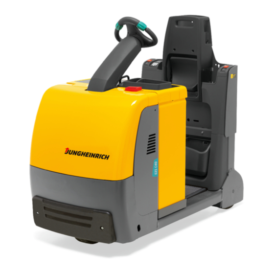
- Page 1 EZS 350 / 350 XL / C40 08.09 - Operating instructions 51133023 11.14 EZS 350 EZS 350 XL EZS C40...
- Page 2 Declaration of Conformity Jungheinrich AG, Am Stadtrand 35, D-22047 Hamburg Manufacturer or agent acting in the European Union Type Option Serial no. Year of manufacture EZS 350 EZS 350 XL EZS C40 Additional information On behalf of Date G EU Conformity Declaration...
- Page 4 Our trucks are subject to ongoing development. Jungheinrich reserves the right to alter the design, equipment and technical features of the system. No guarantee of particular features of the truck should therefore be assumed from the present operating instructions.
- Page 5 Copyright Copyright of these operating instructions remains with JUNGHEINRICH AG. Jungheinrich Aktiengesellschaft Am Stadtrand 35 22047 Hamburg - Germany Tel: +49 (0) 40/6948-0 www.jungheinrich.com...
-
Page 6: Table Of Contents
Table of contents Correct Use and Application ........... General....................Correct application................... Approved application conditions .............. Proprietor responsibilities ................ Adding attachments and/or accessories..........Truck Description ..............Application ....................Assemblies and Functional Description........... Assembly Overview ................. Functional Description ................Technical Specifications ................Performance data .................. - Page 7 Checks and operations to be performed before starting daily operation . Preparing the truck for operation ............. Parking the truck securely ............... Battery discharge monitor................ Industrial Truck Operation ............... Safety regulations for truck operation............Emergency Disconnect, Travel, Steering, Braking ........Pedestrian mode ..................
- Page 8 Appendix JH Traction Battery Operating Instructions These operating instructions apply only to Jungheinrich battery models. If using another brand, refer to the manufacturer's operating instructions.
-
Page 10: A Correct Use And Application
A Correct Use and Application General The truck described in the present operating instructions is an industrial truck designed for towing trailer loads. It must be applied, operated and serviced in accordance with the instructions contained in the present manual. Any other type of use is beyond the scope of application and can result in damage to personnel, the industrial truck or property. -
Page 11: Proprietor Responsibilities
Proprietor responsibilities For the purposes of the present operating instructions the “proprietor” is defined as any natural or legal person who either uses the industrial truck himself, or on whose behalf it is used. In special cases (e.g. leasing or renting) the proprietor is considered the person who, in accordance with existing contractual agreements between the owner and user of the industrial truck, is charged with operational duties. -
Page 12: B Truck Description
B Truck Description Application The truck is a three-wheel electric tow truck with an operator platform, equipped with a Jet Pilot. It is designed for transporting goods on level surfaces in buildings. The drawbar pull is indicated on the data plate. -
Page 13: Assemblies And Functional Description
Assemblies and Functional Description Assembly Overview Item Description Item Description t Front panel o Stop button Battery cover Forward “pedestrian operation” 10 o button t JetPilot 11 o Trailer coupling Emergency Disconnect (main Storage compartment 12 t switch) Travel switch Drive wheel 13 t on EZS C40 = CSE wheel... - Page 14 Reverse “pedestrian operation” Rear view mirror button t = Standard version o = Option...
-
Page 15: Functional Description
– Each time the truck is switched on the system performed an automatic diagnosis. Operator position – Adjustable driver's seat o (EZS 350 XL and EZS C40 only). – All travel and tow operations can be performed sensitively without having to reach. - Page 16 – The battery discharge indicator shows the available battery capacity. – The optional CanDis displays show the key driver information and travel program, service hours, battery capacity and event messages. 2.2.1 Hourmeter Prepare the truck for operation, (see "Preparing the truck for operation" on page 45) or (see "CanCode keypad"...
-
Page 17: Technical Specifications
Technical Specifications Technical specification details in accordance with VDI 2198. Technical modifications and additions reserved. Performance data EZS 350 EZS 350 XL F Nominal drawbar pull 1000 1000 Travel speed 7,0 / 12,5 7,0 / 12,5 km/h w / w.o. rated load 1... -
Page 18: Dimensions
Dimensions... - Page 19 EZS 350 EZS 350 XL Wheelbase 1147 h7 Seat height / standing height - / 132 - / 132 Tiller height 1400 1400 in travel position 1) h10 Coupling height 140 - 480 140 - 480 Overall length 2) 1350...
-
Page 20: Weights
Weights EZS 350 EZS 350 XL EZS C40 Net weight excl. battery Axle load, w.o. load 520 / 456 590 / 520 660 / 525 front/rear + battery Battery weight Tyre type EZS 350 EZS 350 XL EZS C40 Tyre size, drive... -
Page 21: En Norms
EN norms Noise emission level – EZS 350 / 350 XL: 70 dB(A) – EZS C40: 61 dB(A) in accordance with EN 12053 as harmonised with ISO 4871. The noise emission level is calculated in accordance with standard procedures and takes into account the noise level when travelling, lifting and when idle. -
Page 22: Conditions Of Use
Conditions of use Ambient temperature – operating at 5°C to 40°C Special equipment and authorisation are required if the truck is to be constantly used in conditions of extreme temperature or air humidity fluctuations. -
Page 23: Identification Points And Data Plates
Identification points and data plates Item Description Data plate Serial number Warning: “Caution, pushbutton operation” Test plaque Warning: Risk of trapping when reversing Strap points for crane lifting Model description... -
Page 24: Data Plate
Data plate Item Description Item Description Type Year of manufacture Serial number Nominal drawbar pull 5 min. in N Nominal drawbar pull 60 min. in N Output Battery voltage (V) Min./max. battery weight (kg) Net weight w.o. battery (kg) Manufacturer Option Manufacturer’s logo For queries regarding the truck or ordering spare parts always quote the truck serial... -
Page 26: C Transport And Commissioning
C Transport and Commissioning Lifting by crane WARNING! Improper lifting by crane can result in accidents The use of unsuitable lifting gear can cause the truck to crash when being lifted by crane. Prevent the truck from striking other objects when it is being raised, and avoid any involuntary movements. -
Page 27: Transport
Transport WARNING! Accidental movement during transport Improper fastening of the truck and mast during transport can result in serious accidents. Loading must be carried out by specially trained staff in accordance with recommendations contained in Guidelines VDI 2700 and VDI 2703 In each case correct measurements must be made and appropriate safety measures adopted. -
Page 28: Using The Truck For The First Time
Using the Truck for the First Time CAUTION! Only operate the truck with battery current. Rectified AC current will damage the electronic components. Cable connections to the battery (tow leads) must be less than 6 m long and have a minimum cross-section of 50 mm² . Procedure •... -
Page 30: D Battery - Servicing, Recharging, Replacement
D Battery - Servicing, Recharging, Replacement Safety Regulations Governing the Handling of Lead-Acid Batteries Maintenance personnel Batteries may only be charged, serviced or replaced by trained personnel. This operator manual and the manufacturer’s instructions concerning batteries and charging stations must be observed when carrying out the work. Fire protection Do not smoke and avoid naked flames when handling batteries. -
Page 31: Battery Types
3 PzV 360 Ah HX 411 kg Maintenance-free 24 volt battery 798x212x784 mm (LXWXH) 3 PzV 420 Ah 400 kg Maintenance-free Battery type EZS 350 XL / C40 Capacity Weight 24 volt battery 3 PzS 465 Ah 368 kg 626X286X782 mm (LXWXH) - Page 32 Battery type EZS 350 XL / C40 Capacity Weight 24 volt battery 626X286X782 mm (LXWXH) 3 PzV 360 Ah 368 kg Maintenance-free 24 volt battery 628x286x784 mm (LXWXH) 3 PzV 420 Ah 420 kg Maintenance-free 24 volt battery 796X330X782 mm (LXWXH)
-
Page 33: Exposing The Battery
Exposing the battery CAUTION! Trapping hazard Make sure there is nothing between the battery cover and the truck when you fit the battery cover. WARNING! An unsecured truck can cause accidents Parking the truck on an incline is dangerous and is strictly prohibited. Always park the truck on a level surface. -
Page 34: Charging The Battery
Charging the battery WARNING! The gases produced during charging can cause explosions The battery produces a mixture of nitrogen and hydrogen (electrolytic gas) during charging. Gassing is a chemical process. This gas mixture is highly explosive and must not be ignited. Switch the charging station and truck off first before connecting/disconnecting the charging cable of the battery charging station to/from the battery connector. - Page 35 Charging the battery Requirements – Park the truck on a level surface. – Expose the battery, (see "Exposing the battery" on page 32). – Disconnect the battery Procedure • Pull the battery connector (36) from out of the bracket (38). •...
-
Page 36: Battery Removal And Installation
Battery removal and installation WARNING! Accident risk during battery removal and installation Due to the battery weight and acid there is a risk of trapping or scalding when the battery is removed and installed. Note the "Safety regulations for handling acid batteries" section in this chapter. Wear safety shoes when removing and installing the battery. - Page 37 Removing the battery from the side (o) CAUTION! Trapping hazard Trapping hazard when removing and installing the battery. When removing and installing the battery do not put your hands between the battery and the chassis. Battery removal Requirements – Park the truck securely, (see "Parking the truck securely" on page 46). –...
- Page 38 Procedure Installation is the reverse order. When reinstalling the battery, note the proper installation position and make sure the battery is connected correctly. CAUTION! After installing the battery make sure the battery lock (35) is in place to prevent it from sliding out.
-
Page 40: E Operation
E Operation Safety Regulations for the Operation of the Forklift Truck Driver authorisation The truck may only be used by suitably trained personnel, who have demonstrated to the proprietor or his representative that they can drive and handle loads and have been authorised to operate the truck by the proprietor or his representative. - Page 41 Hazardous area WARNING! Risk of accidents / injury in the hazardous area of the truck The hazardous area is defined as the area in which people are at risk from the truck movement or from the load itself. This also includes areas which can be reached by falling loads.
-
Page 42: Displays And Controls
Displays and Controls... - Page 43 Item Control / Display Function t – Activates the truck by applying the Key switch and key control voltage – Removing the key prevents the truck from being switched on by unauthorised personnel t – Steers the truck. JetPilot t Disconnects the battery supply Emergency Disconnect switch –...
-
Page 44: Battery Discharge Indicator
Battery discharge indicator When the truck has been released via the key switch, code lock or ISM, the battery charge status is displayed. The LED (46) colours represent the following conditions: LED colour Residual capacity Green 40 - 100 % Orange 30 - 40 % Flashing... -
Page 45: Starting Up The Truck
Starting up the truck Checks and operations to be performed before starting daily operation WARNING! Damage and other truck or attachment (special equipment) defects can result in accidents. If damage or other truck or attachment (special equipment) defects are discovered during the following checks, the truck must be taken out of service until it has been repaired. -
Page 46: Preparing The Truck For Operation
Preparing the truck for operation Switching on the truck Requirements – For checks and operations to be performed before starting daily operation, (see "Checks and operations to be performed before starting daily operation" on page 44). Procedure • Step onto the operator platform (45). •... -
Page 47: Parking The Truck Securely
Parking the truck securely WARNING! An unsecured truck can cause accidents Parking the truck on an incline is dangerous and is strictly prohibited. Always park the truck on a level surface. In special cases the truck may need to be secured with wedges. -
Page 48: Industrial Truck Operation
Industrial Truck Operation Safety regulations for truck operation Travel routes and work areas Only use lanes and routes specifically designated for truck traffic. Unauthorised third parties must stay away from work areas. Loads must only be stored in places specially designated for this purpose. The truck must only be operated in work areas with sufficient lighting to avoid danger to personnel and materials. - Page 49 Negotiating lifts and docks Lifts may only be entered if they have sufficient capacity, are suitable for driving on and authorised for truck traffic by the owner. The driver must satisfy himself of the above before entering these areas. The truck must enter lifts with the load in front and must take up a position which does not allow it to come into contact with the walls of the lift shaft.
-
Page 50: Emergency Disconnect, Travel, Steering, Braking
Emergency Disconnect, Travel, Steering, Braking 4.2.1 Emergency Disconnect Pressing the Emergency Disconnect switch Procedure CAUTION! Accident risk The operation of the Emergency Disconnect switch must not be affected by any objects placed in its way. Do not use the Emergency Disconnect switch (4) as a service brake. •... - Page 51 4.2.2 Travel CAUTION! Do not drive the truck unless the panels and covers are closed and properly locked. Requirements – Start up the truck, (see "Starting up the truck" on page 44) Procedure • Control the travel speed with the travel switch (5). •...
- Page 52 4.2.4 Brakes WARNING! Accident risk The brake pattern of the truck depends largely on the ground conditions. The driver must be aware of travel route conditions and them into account when braking. Brake with care to prevent the load from slipping. Allow for increased braking distance when travelling with an attached load.
- Page 53 Regenerative braking Procedure • Release the travel switch (5) - the travel switch (5) reverts to neutral. The truck brakes to a halt regeneratively via the coasting brake. The service brake then applies. Regenerative braking may not be sufficient on inclines. In this case inversion braking must be applied.
-
Page 54: Pedestrian Mode
Pedestrian mode CAUTION! Risk of trapping Steering set straight-ahead. The operator must always stand beside the truck during pedestrian operation. There must be no persons standing between the truck and any obstacles. There must be no persons on the operator platform. In pedestrian mode the truck can be operated by the operator from either side while walking alongside. -
Page 55: Coupling Types
Coupling Types CAUTION! Trapping hazard There is a trapping risk when you attach a trailer. Follow the instructions of the coupling manufacturer if using special trailer couplings. Secure the trailer to prevent it from rolling away before coupling it. Do not get caught between the truck and the tiller when coupling the trailer. The tiller must be horizontal, tilted down by no more than 10°... - Page 56 4.4.2 Rockinger coupling with hand lever or remote control (o) CAUTION! Incorrectly coupled trailers can cause accidents Make sure the coupling is engaged securely before starting the truck. The contro pin (52) must be flush with the control sleeve (51). Hitching the trailer Procedure •...
-
Page 57: Travelling With Trailers
Travelling with trailers WARNING! Towed load In difficult application conditions (inclines, smooth or slippery travel routes) the tow load must have to be reduced to ensure braking without risk of accidents. The maximum load specified applies only for towing on level, non-slip ground with sufficient capacity. -
Page 58: Seat (O) (Xl And C40 Only)
Seat (o) (XL and C40 only) Adjust the seat Procedure • Fold the seat (52) out. • Pull the seat (52) towards you and push it into the required position. • To adjust the position, release the seat so that it falls into the required position. The seat is now set. -
Page 59: Troubleshooting
Troubleshooting This chapter enables the user to identify and rectify basic faults and the effects of incorrect operation. When trying to locate a fault, proceed in the order shown in the table. If, after carrying out the following remedial action, the truck cannot be restored to operation or if a fault in the electronics system is displayed with a corresponding error code, contact the manufacturer’s service department. -
Page 60: Operating The Truck Without Its Own Drive System
Operating the truck without its own drive system WARNING! Uncontrolled truck movement When the brakes are de-activated the truck must be parked on a level surface, since the brakes are no longer effective. Do not release the brake on slopes or inclines. Apply the brake again when you reach your destination. -
Page 61: Optional Equipment
Optional equipment CanDis display instrument The instrument indicates: Battery charge display (on board charger only) LED bars for battery charge status "Warning" symbol (yellow), Battery charge recommended "Stop" symbol (red); Battery charge essential "T" symbol appears during operation when the discharge indicator is set to maintenance-free battery 6 digit LCD display: –... - Page 62 7.1.1 Discharge monitor function The discharge limit has been reached when the "Stop" symbol (57) lights up. When the discharge monitor function is activated the travel speed is reduced by half. The maximum travel speed is only enabled again when the battery is 70% charged. 7.1.2 Service hour display The service hour display range is between 0.0 and 99,999.0 hours.
-
Page 63: Cancode Keypad
CanCode keypad CanCode keypad The keypad consists of 10 digit keys, a Set key and a o key. The O key indicates the follow operating statuses via a red / green LED: – Code lock function (starting up the truck). –... - Page 64 Parameter Groups The parameter number is composed of three digits. The first digit refers to the parameter group as shown in Table 1. The second and third digits are numbered in sequence from 00 to 99. Parameter Groups Code lock settings (codes, travel program release, automatic cutout, etc.) 7.2.3 Parameter Settings To change the truck settings you must enter the master code.
- Page 65 Parameter list Function Setting range Standard Procedure setting Change master code: 0000 - 9999 7295 – (LED 60 flashes) The length (4-6 digits) of Confirm current the master code also 00000 - 99999 code entry determines the length of – the operator code (4-6 000000 - 999999 (Set 64)
- Page 66 Function Setting range Standard Procedure setting Delete code 0000 - 9999 – (LED 61 flashes) Confirm new code 00000 - 99999 entry – 000000 - 999999 (Set 64) – (LED 62 flashes) repeat code entry – (Set 64) Delete code log (deletes 3265 –...
- Page 67 Setting the travel program configuration to a code Procedure • Press the O key (63). • Enter the master code. • Enter the three-digit parameter number 024. • Confirm with the SET key (64). • Enter the code to be changed and confirm with SET. •...
-
Page 68: Setting The Truck Parameters With Cancode
Setting the truck parameters with CanCode CAUTION! Faulty entry Without CanDis only CanCode internal parameters can be changed. Traction controller parameters can only be changed with CanDis, without CanDis the settings must be performed by the manufacturer's service department. CAUTION! Altering travel parameters can cause accidents Increasing the settings for acceleration, steering and travel can result in accidents. -
Page 69: Ism Access Module (O)
Checking the settings in programming mode Procedure • Select the travel program to be worked on after changing the parameter value, and confirm with the Set key (64). The truck is now in travel mode and can be checked. To continue setting, confirm with the Set key (64) again. Saving travel parameters Requirements –... -
Page 70: Parameters
Parameters Travel program 1 (up to 10.11) Function Setting Standard Comments range setting 0256 Rider mode 0 - 9 acceleration 0257 Pedestrian mode 0 - 9 acceleration 0260 Rider mode 0 - 9 coasting brake 0261 Pedestrian mode 0 - 9 coasting brake 0264 Maximum forward depending on travel... - Page 71 Travel program 1 (from 11.11) Function Setting range Standard Comments setting 0256 Rider mode acceleration 30 - 105 0257 Pedestrian mode 2 - 21 acceleration 0260 Rider mode coasting 20 - 250 brake 0261 Pedestrian mode coasting 20 - 250 brake 0264 Maximum forward speed 0 - 125...
- Page 72 Travel program 2 (up to 10.11) Function Setting Standard Comments range setting 0272 Rider mode 0 - 9 acceleration 0273 Pedestrian mode 0 - 9 acceleration 0276 Rider mode 0 - 9 coasting brake 0277 Pedestrian mode 0 - 9 coasting brake 0280 Maximum forward depending on travel...
- Page 73 Travel program 2 (from 11.11) Function Setting range Standard Comments setting 0272 Rider mode acceleration 30 - 105 0273 Pedestrian mode 2 - 40 acceleration 0276 Rider mode coasting brake 56 - 250 0277 Pedestrian mode coasting 20 - 250 brake 0280 Maximum forward speed 0 - 125...
- Page 74 Travel program 3 (up to 10.11) Function Setting Standard Comments range setting 0288 Rider mode 0 - 9 acceleration 0289 Pedestrian mode 0 - 9 acceleration 0292 Rider mode 0 - 9 coasting brake 0293 Pedestrian mode 0 - 9 coasting brake 0296 Maximum forward depending on travel...
- Page 75 Travel program 3 (from 11.11) Function Setting range Standard Comments setting 0288 Rider mode acceleration 30 - 105 0289 Pedestrian mode 2 - 40 acceleration 0292 Rider mode coasting brake 20 - 250 0293 Pedestrian mode coasting 20 - 250 brake 0296 Maximum forward speed 0 - 125...
- Page 76 Battery parameters (from 11.11) Function Setting Standard Comments range setting 1377 Battery type 0 - 7 0 = Normal (wet) (normal / high 1 = High performance (wet) performance / dry) 2 = Dry (maintenance-free) 3 = US "Flate Plate" type 4 = US "Pallet Pro"...
-
Page 78: F Industrial Truck Maintenance
F Industrial Truck Maintenance Operational Safety and Environmental Protection The checks and servicing operations contained in this chapter must be performed in accordance with the intervals as indicated in the servicing checklists. WARNING! Risk of accidents and damage to components All modifications to the forklift truck assemblies, in particular the safety mechanisms, are prohibited. - Page 79 Lifting and jacking up WARNING! Lifting and jacking up the truck safely In order to raise the truck, the lifting gear must only be secured to the points specially provided for this purpose. You may only work under a raised load handler / raised cab if they have been secured with a sufficiently strong chain or the fastening bolt.
- Page 80 Cleaning CAUTION! Fire hazard Do not use flammable liquids to clean the industrial truck. Always disconnect the battery before starting cleaning work. Carry out all necessary safety measures to prevent sparking before cleaning (e.g. by short-circuiting). CAUTION! Risk of electrical system damage The electrical system can be damaged if it is cleaning with water.
- Page 81 Electrical system WARNING! Accident risk Only suitably trained electricians may operate on the truck's electrical system. Before working on the electrical system, take all precautionary measures to avoid electric shocks. Always disconnect the battery before starting cleaning operations. WARNING! Electric currents can cause accidents Make sure the electrical system is voltage-free before starting work on it.
- Page 82 Wheels WARNING! The use of wheels that do not match the manufacturer's specifications can result in accidents. The quality of wheels affects the stability and performance of the truck. Uneven wear affects the truck's stability and increases the stopping distance. When replacing wheels make sure the truck is not skewed.
- Page 83 NOTE Testing and replacing hydraulic hoses Hydraulic hoses can become brittle through age and must be checked at regular intervals. The application conditions of the industrial truck have a considerable impact on the ageing of the hydraulic hoses. Check the hydraulic hoses at least annually and replace if necessary. If the operating conditions become more arduous the inspection intervals must be reduced accordingly.
-
Page 84: Servicing And Inspection
The application conditions of an industrial truck have a considerable impact on the wear of the service components. We recommend that a Jungheinrich customer service adviser carries out an application analysis on site to work out specific service intervals to prevent damage due to wear. -
Page 85: Maintenance Checklist
Maintenance checklist Owner 4.1.1 Standard equipment Brakes W A B C Test brakes. Electrical System W A B C Test warning and safety devices in accordance with operating instructions. Test displays and controls. Test Emergency Disconnect switch. Power Supply W A B C Check battery cable connections are secure, grease terminals if necessary. - Page 86 4.1.2 Optional equipment Work lights Electrical System W A B C Test lighting. Strobe light/beacon Electrical System W A B C Test strobe light / beacon and check for damage.
-
Page 87: Customer Service
Customer Service 4.2.1 Standard equipment Brakes W A B C Check magnetic brake air gap. Electrical System W A B C Test cable and motor attachments. Test warning and safety devices in accordance with operating instructions. Test displays and controls. Test Emergency Disconnect switch. - Page 88 Agreed performance levels W A B C Carry out a test run with rated load, if necessary with a customer- specific load. Lubricate truck according to the lubrication schedule. Demonstration after servicing. Steering W A B C Test electric steering and its components.
- Page 89 4.2.2 Optional equipment Discharge strap (EZS C40 only) Electrical System W A B C Check anti-static discharge strap is present and not damaged. Audible warning devices Electrical System W A B C Test the buzzer / warning alarm, check for damage and make sure it is secure.
- Page 90 Data radio System components W A B C Test scanner and terminal, check for damage and make sure they are secure and clean. Check fuse ratings. Check wiring is secure and check for damage. Electrolyte recirculation Power Supply W A B C Replace air filter wadding.
-
Page 91: Lubricants And Lubrication Schedule
Lubricants and Lubrication Schedule Handling consumables safely Handling consumables Consumables must always be handled correctly. Follow the manufacturer’s instructions. WARNING! Improper handling is hazardous to health, life and the environment Consumables can be flammable. Keep consumables away from hot components and naked flames. Always keep consumables in prescribed containers. - Page 92 Consumables and used parts CAUTION! Consumables and used parts are an environmental hazard Used parts, oils and fuels must be disposed of in accordance with the relevant environmental protection regulations. To change the oil contact the manufacturer's customer service department, who have been specially trained for this task. Note the safety regulations when handling these materials.
-
Page 93: Lubrication Schedule
Lubrication Schedule 1,4 l 1,4 l g Contact surfaces k Cold Store Application s Grease nipple b Transmission oil filler neck a Transmission oil drain plug Hydraulic oil filler neck 1 Compound ratio for cold store usage 1:1... -
Page 94: Consumables
Consumables Code Order no. Package Component Used for quantity 50 380 904 5.0 l HSY 75W-90 Transmission 29 200 670 5.0 l H-LP 46, DIN 51524 29 202 050 1.0 kg Grease, Polylube Lubrication GA 352P Grease guidelines Code Saponification Dew point Worked NLG1 class Application... -
Page 95: Maintenance And Repairs
Maintenance and repairs Preparing the truck for maintenance and repairs All necessary safety measures must be taken to avoid accidents when carrying out maintenance and repairs. The following preparations must be made: Procedure • Park the truck on a level surface. •... -
Page 96: Tightening The Wheel Nuts
Tightening the wheel nuts The wheel nuts on the drive wheel must be retightened in accordance with the maintenance intervals indicated in the maintenance checklist, (see "Servicing and Inspection" on page 83). Tightening the wheel nuts Requirements – Prepare the truck for maintenance and repairs, (see "Preparing the truck for maintenance and repairs"... -
Page 97: Removing The Front Panel
Removing the front panel Front panel disassembly Requirements – Open the battery panel, (see "Exposing the battery" on page 32). Tools and Material Required – Allen key Procedure • Remove the hex socket screws (69) located under the battery cover using a hex socket wrench. -
Page 98: Checking Electrical Fuses
Checking electrical fuses Check fuses Requirements – Truck prepared for maintenance and repairs, (see "Preparing the truck for maintenance and repairs" on page 94). – Front panel removed, (see "Removing the front panel" on page 96). Procedure • Check the fuse ratings against the table and replace if necessary. The fuses are now checked. -
Page 99: Restoring The Truck To Service After Maintenance And Repairs
Restoring the truck to service after maintenance and repairs Procedure • Thoroughly clean the truck. • Lubricate the truck according to the lubrication schedule, (see "Lubrication Schedule" on page 92). • Clean the battery, grease the terminals and connect the battery. •... -
Page 100: Decommissioning The Industrial Truck
Decommissioning the industrial truck If the truck is to be out of service for more than a month, e.g. for commercial reasons, it must be stored in a frost-free and dry room. All necessary measures must be taken before, during and after decommissioning as described hereafter. WARNING! Lifting and jacking up the truck safely In order to raise the truck, the lifting gear must only be secured to the points specially... -
Page 101: During Decommissioning
• Spay all exposed electrical contacts with a suitable contact spray. During decommissioning NOTE Full discharge can damage the battery Self-discharge can cause the battery to fully discharge. Full discharge shortens the useful life of the battery. Charge the battery at least every 2 months. Charge the battery, (see "Charging the battery"... -
Page 102: Restoring The Truck To Service After Decommissioning
Restoring the truck to service after decommissioning Procedure • Thoroughly clean the truck. • Lubricate the truck according to the lubrication schedule, (see "Lubrication Schedule" on page 92). • Clean the battery, grease the terminals and connect the battery. • Charge the battery, (see "Charging the battery" on page 33). •... -
Page 103: Safety Tests To Be Performed At Intervals And After Unusual Incidents
Perform a safety check in accordance with national regulations. Jungheinrich recommends the truck be checked to FEM guideline 4.004. The Jungheinrich safety department has trained personnel who are able to carry out inspections. The truck must be inspected at least annually or after any unusual event by a qualified inspector (be sure to comply with national regulations). - Page 104 A Traction Battery Appendix Contents Traction Battery Appendix............Correct Use and Application..............Data plate ....................Safety Instructions, Warning Indications and other Notes ....... Lead acid batteries with armour plated cells and liquid electrolyte..Description....................Operation....................Servicing lead-acid batteries with armour plated cells......PzV and PzV-BS lead-acid batteries with sealed armour plated cells..
-
Page 105: Correct Use And Application
Correct Use and Application Failure to observe the operating instructions, carrying out repairs with non-original spare parts, tampering with the battery or using electrolyte additives will invalidate the warranty. Observe the instructions for maintaining the safety rating during operation for batteries in accordance with Ex I and Ex II (see relevant certification). -
Page 106: Safety Instructions, Warning Indications And Other Notes
Safety Instructions, Warning Indications and other Notes Used batteries must be treated as hazardous waste. These batteries are marked with the recycling symbol and the sign showing a crossed-out rubbish bin, and should not be disposed of with ordinary household waste. waste. -
Page 107: Lead Acid Batteries With Armour Plated Cells And Liquid Electrolyte
Lead acid batteries with armour plated cells and liquid electrolyte Description Jungheinrich traction batteries are lead acid batteries with armour plated cells and liquid electrolyte. The names of the traction batteries are PzS, PzB, PzS Lib and PzM. Electrolyte The rated density of the electrolyte assumes a temperature of 30°C and the rated electrolyte level is fully charged. -
Page 108: Operation
Operation 4.2.1 Commissioning unfilled batteries The operations required must be carried out by the manufacturer's customer service department or a customer service organisation authorised by the manufacturer. 4.2.2 Commissioning filled and charged batteries Checks and operations to be performed before starting daily work Procedure •... - Page 109 4.2.4 Charging the battery WARNING! The gases produced during charging can cause explosions The battery gives off a mixture of oxygen and hydrogen (electrolytic gas) during charging. Gassing is a chemical process. This gas mixture is highly explosive and must not be ignited. Always disconnect the charger and truck before connecting or disconnecting the charger and battery.
- Page 110 The electrolyte temperature rises by approx. 10 K during charging. Charging should therefore only begin when the electrolyte temperature is below 45°C. The electrolyte temperature of batteries must be at least +10°C before charging. Otherwise the battery will not charge correctly. Below 10°C the battery is insufficiently charged with standard charging systems.
-
Page 111: Servicing Lead-Acid Batteries With Armour Plated Cells
Servicing lead-acid batteries with armour plated cells Water quality The quality of the water used to fill up electrolyte must correspond to purified or distilled water. Purified water can be produced through distillation or ion exchangers and is then suitable for the production of electrolyte. 4.3.1 Daily –... -
Page 112: Pzv And Pzv-Bs Lead-Acid Batteries With Sealed Armour Plated Cells
PzV and PzV-BS lead-acid batteries with sealed armour plated cells Description PzV batteries are sealed batteries with fixed electrolytes, to which no water can be added over the entire lifespan of the battery. Relief valves are used as plugs which are destroyed when opened. -
Page 113: Operation
Operation 5.2.1 Commissioning Checks and operations to be performed before starting daily work Procedure • Make sure the battery is in physically good condition. • Make sure the terminals are correct (positive to positive and negative to negative) and check that contacts on the battery terminal conducting system are secure. •... - Page 114 NOTE Charging the battery incorrectly can result in material damage. Incorrect battery charging can result in overloading of the electric wires and contacts, hazardous gas formation and electrolyte leakage from the cells. Always charge the battery with DC current. All DIN 41773 charging procedures are permitted in the format approved by the manufacturer.
- Page 115 Charging the battery Requirements – Electrolyte temperature between +15°C and 35°C Procedure • Open or take off the tray lid or covers from the battery compartment. • Connect the battery to the switched off charger, ensuring the terminals are connect (positive to positive and negative to negative).
-
Page 116: Servicing Pzv And Pzv-Bs Lead-Acid Batteries With Sealed Armour Plated Cells
Servicing PzV and PzV-BS lead-acid batteries with sealed armour plated cells Do not add water! 5.3.1 Daily – Charge the battery after each discharge. 5.3.2 Weekly – Visually inspect for dirt and physical damage. 5.3.3 Every three months – Measure and record the overall voltage. –... -
Page 117: Aquamatik Water Replenishment System
Aquamatik water replenishment system Water replenishment system design > 3 m Water container Tap connection with ball cock Flow indicator Shut-off cock Locking coupling Battery lock connector... -
Page 118: Functional Description
Functional Description The Aquamatik water replenishment system is used to adjust the rated electrolyte level automatically on traction batteries for industrial trucks. The battery cells are interconnected through hoses and are attached to the water supply (e.g. water container) through a plug connection. When the shut-off cock is opened all the cells are filled with water. -
Page 119: Filling Time
Filling time The filling time for a battery depends on the electrolyte level, the ambient temperature and the filling pressure. Filling ends automatically. The water supply line must be disconnected from the battery when the water has been filled. Water quality The quality of the water used to fill up electrolyte must correspond to purified or distilled water. -
Page 120: Cleaning Measures
Cleaning measures The plug systems must only be cleaned with purified water in accordance with DIN 43530-4. No parts of the plugs must come into contact with solvent-based materials or soap. 6.10 Service mobile vehicle Mobile water filling vehicle with pump and filling gun to fill individual cells. The immersion pump in the container generates the necessary filling pressure. -
Page 121: Electrolyte Circulation
Electrolyte circulation Functional Description Electrolyte circulation ensures the supply of air during charging to mix the electrolyte, thereby preventing any acid layer, shortening the charge time (charge factor approx. 1.07) and reducing the formation of gas during charging. The charger must be suitable for the battery and electrolyte circulation. - Page 122 NOTE If an installed electrolyte circulation system is seldom used or not used at all, or if the battery is subjected to severe temperature fluctuations, the electrolyte may flow back into the hose system. Attach a separate coupling system to the air inlet line, such as: locking coupling on the battery side and through-coupling on the air supply side.
-
Page 123: Cleaning Batteries
Cleaning batteries Batteries and trays must be cleaned in order to – maintain cell insulation and protect cells from ground or external conductive parts. – Avoid damage from corrosion and stray currents. – Avoid excessive and varying automatic discharge of the individual cells or block batteries due to stray currents. - Page 124 Cleaning the battery with a high pressure cleaner Requirements – Cell connectors tight, plugged in securely – Cell plugs closed Procedure • Follow the high pressure cleaner's user instructions. • Do not use any cleaning additives. • Observe the permissible cleaning device temperature setting of 140°C. This generally ensures that the temperature does not exceed 60°C at a distance of 30cm behind the outlet nozzle.
-
Page 125: Storing The Battery
Storing the battery NOTE The battery should not be stored for longer than 3 months without charging as otherwise it will no longer be functional. If the battery is to be taken out of service for a long period, it should be stored fully charged in a dry room protected from frost.
Need help?
Do you have a question about the EZS 350 and is the answer not in the manual?
Questions and answers