PDi PERSONA 10 Service Manual
Hospital-grade lcd
television receiver
pdi-p10 lcdd
Hide thumbs
Also See for PERSONA 10:
- Installation and operating instructions manual (17 pages) ,
- Installation & operating instructions manual (21 pages) ,
- Installation & operating instructions manual (33 pages)
Table of Contents
Advertisement
Communication
Systems Inc.
Better Solutions Are Within Reach™
Service
Manual
Communication
Systems, Inc
.
40 Greenwood Lane
Springboro, Ohio 45066
PH: 937-743-6010
FX: 937-743-5664
http://www.pdiarm.com
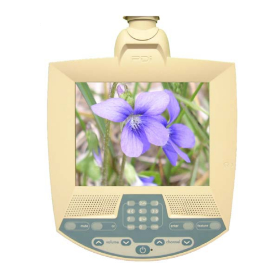
PDI-P10LCDD TV Service Manual
PERSONA
Hospital-Grade LCD
Television Receiver
MODEL PDI-P10 LCDD
Better Solutions Are Within Reach
Page 1 of 32
10
®
Document Number: PD196-068R5
Advertisement
Table of Contents

Related Manuals for PDi PERSONA 10


Summary of Contents for PDi PERSONA 10
-
Page 1: Service Manual
Communication Page 1 of 32 PDI-P10LCDD TV Service Manual Systems Inc. Better Solutions Are Within Reach™ PERSONA Service Manual Hospital-Grade LCD Television Receiver Communication MODEL PDI-P10 LCDD Systems, Inc 40 Greenwood Lane ® Better Solutions Are Within Reach Springboro, Ohio 45066... -
Page 2: Regulatory Information
Copyright 2009 by PDI Communication Systems, Inc. All rights reserved. Disclaimer The author and publisher have used their best efforts in preparing this manual. PDI Communication Systems, Inc. makes no representation or warranties with respect to the accuracy or completeness of the contents of this manual... -
Page 3: Product Identification
Communication Page 3 of 32 PDI-P10LCDD TV Service Manual Systems Inc. Better Solutions Are Within Reach™ Product Identification Product Label The P10LCDD is easily identified using the product label located in the center of the back housing. Serial Number The serial number is located at the lower right corner of the product label. -
Page 4: Warnings
It is also important to understand that these CAUTIONS and WARNINGS are not exhaustive PDI could not possibly know, evaluate, and advise the service industry of all conceivable methods in which service might be done or of the possible hazardous consequences of each method. Accordingly, a... -
Page 5: Table Of Contents
Communication Page 5 of 32 PDI-P10LCDD TV Service Manual Systems Inc. Better Solutions Are Within Reach™ Table of Contents Copyright, Disclaimer, and Trademarks.................. 2 Regulatory Information......................2 Product Identification......................3 Warnings..........................4 Product Safety Servicing Precautions..................4 Picture Adjustments ........................ 5 Disinfecting and Cleaning ....................... -
Page 6: Disinfecting And Cleaning
Communication Page 6 of 32 PDI-P10LCDD TV Service Manual Systems Inc. Better Solutions Are Within Reach™ Disinfecting and Cleaning The P10LCDD should be disinfected before performing any service. The following procedure is only a recommendation. Your hospital or company may have a different procedure to follow. -
Page 7: Replaceable Parts
Communication Page 7 of 32 PDI-P10LCDD TV Service Manual Systems Inc. Better Solutions Are Within Reach™ Replaceable Parts - Exploded diagram This diagram shows the order that the different parts of the P10LCDD fit together. List of tools Phillips screwdriver... - Page 8 Communication Page 8 of 32 PDI-P10LCDD TV Service Manual Systems Inc. Better Solutions Are Within Reach™ EMI Shield The EMI Shield mounts over the TV’s main board and provides protection from electromagnetic interference. EMI Shield Part #: PD130-001 Housing Components include the front with crystal clear window and foam seals, rear housing, and swivel assembly.
-
Page 9: Lcd Panel
Communication Page 9 of 32 PDI-P10LCDD TV Service Manual Systems Inc. Better Solutions Are Within Reach™ INOVA-10 Swivel Assembly Part #: PD290-100 Keypad The keypad fits into the cavity below the speaker vents on the front housing. Keypad Part #: PD134-237 LCD Panel The LCD panel is what displays the images the TV receives. -
Page 10: Replaceable Parts
Communication Page 10 of 32 PDI-P10LCDD TV Service Manual Systems Inc. Better Solutions Are Within Reach™ Replaceable Parts Chassis The circuit board and the LCD panel are attached to the chassis. It also helps give the unit rigidity. Chassis Part #: PD186-001 Speaker Assembly The speaker assembly attaches to the front cabinet and is replaceable. - Page 11 Communication Page 11 of 32 PDI-P10LCDD TV Service Manual Systems Inc. Better Solutions Are Within Reach™ Replaceable Parts Swivel Assembly The swivel assembly allows the TV to be tilted and panned. It also houses the coax and USB cables. Swivel Assembly...
- Page 12 Communication Page 12 of 32 PDI-P10LCDD TV Service Manual Systems Inc. Better Solutions Are Within Reach™ Replaceable Parts Main board This is the circuit board where the LCD panel, inverter, F-connector, and keypad are connected. Main board Part #: PD128-1434 IR Board This is the circuit board where the speaker assembly and keypad are connected.
-
Page 13: Main Circuit Board Layout And Interconnects
Communication Page 13 of 32 PDI-P10LCDD TV Service Manual Systems Inc. Better Solutions Are Within Reach™ Coax RF Power— LCD backlight “F” Connector Connector Main circuit board layout and interconnections USB cable Connector LCD panel Earphone jack Connector Keypad Connector... -
Page 14: Disassembling
Communication Page 14 of 32 PDI-P10LCDD TV Service Manual Systems Inc. Better Solutions Are Within Reach™ Disassembling Step 1 Picture 1D Lay the P10LCDD face down on a soft work surface. (Picture 1D) Step 2 Picture 2D Remove the socket cap with an Allen wrench. (Picture 2D) - Page 15 Communication Page 15 of 32 PDI-P10LCDD TV Service Manual Systems Inc. Better Solutions Are Within Reach™ Disassembling Step 3 Picture 3D Use a Phillips screwdriver to remove the 7 screws from the rear housing. (Picture 3D) Remove the rear housing from the unit.
- Page 16 Communication Page 16 of 32 PDI-P10LCDD TV Service Manual Systems Inc. Better Solutions Are Within Reach™ Disassembling Step 5 Picture 5D Before handling the main board be sure that you have taken precautions to protect it and other the parts from Electrostatic Discharge.
- Page 17 Communication Page 17 of 32 PDI-P10LCDD TV Service Manual Systems Inc. Better Solutions Are Within Reach™ Disassembling Step 7 Picture 7D Remove the IR board (PD128-1435) by pinching on each of the two prongs on the front housing that it is placed on and lifting up on the board.
- Page 18 Communication Page 18 of 32 PDI-P10LCDD TV Service Manual Systems Inc. Better Solutions Are Within Reach™ Disassembling Step 9 Picture 10D Use a Phillips screwdriver to remove the 2 screws that connect the speaker assembly to the front housing. Remove the speaker assembly from the front housing. (Picture 10D)
- Page 19 Communication Page 19 of 32 PDI-P10LCDD TV Service Manual Systems Inc. Better Solutions Are Within Reach™ Disassembling Step 11 Picture 12D Use a Phillips screwdriver to remove the 12 screws that connect the chassis to the front housing. (Picture 12D) Lift up on the bottom end of the chassis and remove the keypad cable that is threaded through the slot on the chassis.
- Page 20 Communication Page 20 of 32 PDI-P10LCDD TV Service Manual Systems Inc. Better Solutions Are Within Reach™ Disassembling Step 13 Picture 14D Remove the keypad from the front housing. If it cannot be removed from the front housing cavity, contact technical support.
-
Page 21: Reassembling
Communication Page 21 of 32 PDI-P10LCDD TV Service Manual Systems Inc. Better Solutions Are Within Reach™ Reassembling Step 1 Picture 1R Place the front housing face up on a soft working surface. (Picture 1R) Step 2 Picture 2R Picture 3R If a keypad is not attached to the front housing cavity, thread the flat cable of the keypad through the slot in the front housing of the cavity. - Page 22 Communication Page 22 of 32 PDI-P10LCDD TV Service Manual Systems Inc. Better Solutions Are Within Reach™ Reassembling Step 3 Picture 4R Attach the keypad by abutting the top edge of the keypad to the upper edge of the cavity. The keypad must be laid in place from left-to-right.
- Page 23 Communication Page 23 of 32 PDI-P10LCDD TV Service Manual Systems Inc. Better Solutions Are Within Reach™ Reassembling Step 5 Picture 6R Picture 7R IR board assembly. Connect the keyboard cable and speaker wire to the associated connectors on the IR board. The keypad cable is inserted into the P1 connector. (Picture 6R) Be sure to push in the tabs on both sides of the connector to secure the cable in it.
- Page 24 Communication Page 24 of 32 PDI-P10LCDD TV Service Manual Systems Inc. Better Solutions Are Within Reach™ Reassembling Step 7 Picture 9R Picture 10R Place the LCD panel face down on the work surface. (Picture 9R) Place the chassis over it, and before letting the chassis rest, thread the data cable and LCD backlight cables through the slots on the chassis.
- Page 25 Communication Page 25 of 32 PDI-P10LCDD TV Service Manual Systems Inc. Better Solutions Are Within Reach™ Reassembling Step 9 Picture 13R Picture 14R Place the main board on the chassis and align the four holes near its edges with four holes that are protruding from the chassis.
- Page 26 Communication Page 26 of 32 PDI-P10LCDD TV Service Manual Systems Inc. Better Solutions Are Within Reach™ Reassembling Step 11 Picture 17R Position the chassis over the 2 alignment pins on the left side of the front housing. (Picture 17R) Step 12 Picture 18R Route the wide end of keypad through the slot at the bottom of the chassis.
- Page 27 Communication Page 27 of 32 PDI-P10LCDD TV Service Manual Systems Inc. Better Solutions Are Within Reach™ Reassembling Step 13 Picture 19R Attach the wide end of the keypad cable to the associated connector at the bottom, center of the main board. Press the brown connector latch down to secure the cable into the connector.
- Page 28 Communication Page 28 of 32 PDI-P10LCDD TV Service Manual Systems Inc. Better Solutions Are Within Reach™ Reassembling Step 15 Picture 22R Route the end of the coax and USB cables through the swivel assembly lid seal and top shroud from the top of the assembly.
- Page 29 Communication Page 29 of 32 PDI-P10LCDD TV Service Manual Systems Inc. Better Solutions Are Within Reach™ Reassembling Step 17 Picture 26R Picture 27R Insert the USB cable into the connector at the bottom, right of the main board. (Picture 26R) Insert the coax cable into the coax connector at the top, right of the main board.
- Page 30 Communication Page 30 of 32 PDI-P10LCDD TV Service Manual Systems Inc. Better Solutions Are Within Reach™ Step 19 NOTE: Before attaching the EMI shield perform the Swivel Resistance safety check on page 31. Picture 29R Attach the EMI shield to chassis with screws in 8 places using 2.75 -3.25 in-lbs of torque. The cables need to run through the slots at the top of the shield.
-
Page 31: Safety Checks
Communication Page 31 of 32 PDI-P10LCDD TV Service Manual Systems Inc. Better Solutions Are Within Reach™ Safety checks 1. Swivel Resistance A. Value should read greater than 1 Meg. (A lesser reading indicates a possible insulation breakdown or short between the internal... -
Page 32: Troubleshooting
Communication Page 32 of 32 PDI-P10LCDD TV Service Manual Systems Inc. Better Solutions Are Within Reach™ Troubleshooting SYMPTOM CHECK Verify TV is powered. • Check TV operation with remote control. • Verify that ribbon is seated correctly to P701 •...
Need help?
Do you have a question about the PERSONA 10 and is the answer not in the manual?
Questions and answers