
Subscribe to Our Youtube Channel
Related Manuals for Hubbell CE110


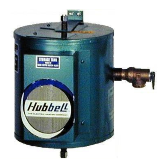
Summary of Contents for Hubbell CE110
- Page 1 INSTALLATION, OPERATION AND MAINTENANCE MANUAL FOR COMMERCIAL ELECTRIC WATER HEATER BASE MODEL “ CE110 ” 2009 Edition...
- Page 2 INTERNET: Always reference the full model number and serial number when calling the factory. The following information should be noted at time of installation and retained for future reference. Serial No.: Date Installed: Dealer's Name: Address: City and State: HUBBELL ELECTRIC HEATER COMPANY P.O.BOX 288 STRATFORD, CT 06615...
-
Page 3: Warning / Caution
A qualified installer is a person who has licensed training and a working knowledge of the applicable codes regulation, tools, equipment, and methods necessary for safe installation of an electric resistance water heater. If questions regarding installation arise, check your local plumbing and electrical inspectors for proper procedures and codes. -
Page 4: Table Of Contents
SECTION TITLE GENERAL INFORMATION INSTALLATION GUIDELINES SCHEDULED MAINTENANCE AND OPERATION TROUBLESHOOTING SERVICING AND REPLACEMENT OF PARTS WARRANTY TABLE OF CONTENTS PAGE #... -
Page 5: Parts Location Diagram
High Limit Access Cover High Limit Safety Switch - Manual reset switch designed to shut off all electrical circuits if water reaches 190°F Thermostat For constant temperature control. Factory set at 125°F. Thermostat and Heating Element Access Cover Long-Life Heating Element - Waste is reduced with immersed heating element because all available heat passes directly into the water. -
Page 6: General Information
- GENERAL INFORMATION GENERAL DESCRIPTION This book describes a packaged electric water heater that is a stationary, self-contained unit. The complete assembly consists of the storage tank, immersion electric heating element(s), thermostat, safety relief valve, safety high temperature cut out, and any other required electrical operating control. -
Page 7: Installation Guidelines
UNPACKING AND INSPECTING THE HEATER 1. Remove the model CE110 from the shipping carton and visually inspect for any sign of damage. A damaged unit should not be installed, but returned to the factory for replacement. -
Page 8: Piping Installation
PIPING INSTALLATION NOTE: The most effective means for preventing deterioration from accelerated corrosion due to galvanic and stray current is the installation of dielectric fittings/unions. The installation of these fittings is the responsibility of the installing contractor. 1. Connect the cold water inlet and hot water outlet to the appropriate connections as shown;... -
Page 9: Final Checks
Shut-off valve installed on cold water line. Hot water line connected to hot water outlet on tank. Temperature and pressure relief valve installed. Relief valve overflow line installed. Water heater filled with water. Power leads connected inside electrical enclosure from separate fused circuit. Ground wire connected. - Page 10 INSTALLATION WITHOUT TEMPERING VALVE Piping to Hot Water Support Bracket – (bottom bracket not shown) Temperature & Pressure Relief Valve Relief Valve Discharge Pipe Drain Valve Piping from Cold Water Air Gap Floor Drain...
- Page 11 INSTALLATION WITH TEMPERING VALVE Piping to Tempering Hot Water Valve Support Bracket – (bottom bracket not shown) Piping from Cold Water Temperature & Pressure Relief Valve Drain Valve Air Gap Relief Valve Discharge Pipe Floor Drain...
-
Page 12: Quarterly Inspection
MAINTENANCE AND OPERATION The water heater is automatic in its operation. It will maintain a full tank of water at the temperature setting of the thermostat. The water heater should not be turned on without first making sure that the tank is full of water and that all air has been released. -
Page 13: Long Term Shut Down
LONG TERM SHUT DOWN 1. If the water heater is to remain idle for an extended period of time, the power and water to the heater should be turned off to conserve energy. 2. The water heater and piping should be drained, if they might be subjected to freezing temperatures. -
Page 14: Section V - Servicing & Replacement Of Parts
SECTION V Before servicing or replacing any part make sure to turn the power supply switch to the OFF position. SURFACE TEMPERATURE HIGH LIMIT CUT-OFF 1. Disconnect power from unit. 2. Remove access cover. 3. Disconnect the four (4) 14 gauge wires. Control Wires 4. - Page 15 8. Unscrew heating element. 9. Withdraw element assembly. Element Assembly 10. Install Teflon tape and insert new heating element. Thermowell must be above the heating element, in the 12 o’clock position. 11. Rewire element; refer to wiring diagram in Section II. Torque screws per chart in back.
-
Page 16: Relief Valve
RELIEF VALVE 1. Disconnect power from unit. 2. Shut off incoming water supply. 3. Lift test lever on relief valve to relieve pressure in tank. 4. Disconnect overflow piping. 5. Unscrew relief valve, remove assembly and replace with new one. 6. -
Page 17: Warranty
The Electric Heater Co., (hereinafter called, the "Company"), offers the following warranty to the purchaser/owner of this electric water heater. Carefully read the entire warranty. Once you buy this product, the Company assumes you agree with the conditions and limitations of this warranty, and you accept the purchaser's/owner's responsibility for installation and care of the heater. -
Page 18: How To Obtain Service Assistance
When contacting The Electric Heater Co., The following information should be made available: 1. Model and serial numbers of the water heater as listed on the front cover of this manual or on the rating plate on the heater. 2. Address where water heater can be seen. - Page 19 NOTES...
- Page 20 P.O. BOX 288 STRATFORD, CT 06615-0288 PHONE: (203) 378-2659 FAX: (203) 378-3593 INTERNET: http://www.hubbellheaters.com/...
Need help?
Do you have a question about the CE110 and is the answer not in the manual?
Questions and answers